We may receive a commission when you use our affiliate links. However, this does not impact our recommendations.
Spine and Rib Construction opens up a lot of exciting possibilities for woodworking hobbyists.
In the December 2019 Popular Woodworking article: “A Modern Parametric Bench”, I showed how any woodworker could build the project. Over the next few blog posts, I’ll get into additional project details, how to build the project with a CNC, how to build it using the Shaper Origin hand-held CNC, plus a few tricks for using less expensive plywood for projects like this. In this first post, I’d like to add a few details not covered in the article to help you to build a modern parametric bench or table of your own.
More About Parametric Design
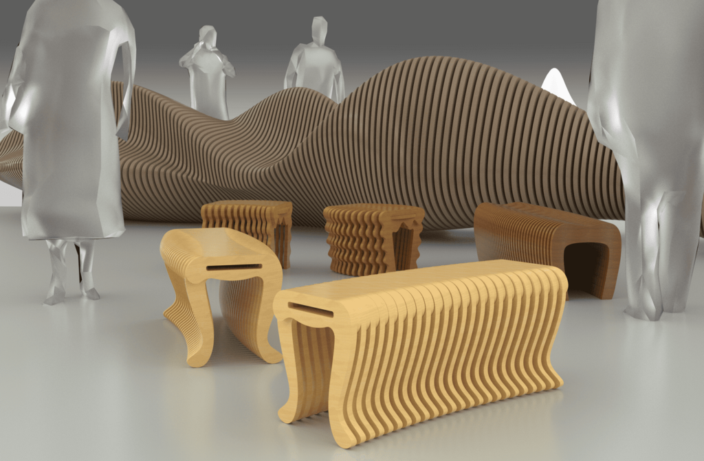
In the article, I mentioned that I’ve worked on other parametric designs. Other than chair and other bench designs, for the most part, my parametric design work is for sculpture projects such as the piece proposed for a technology company shown in the background, above. These large scale works are intended to be built in plywood and machined on CNCs. But, in several other ways, I use parametric and other generative design tools and techniques extensively — particularly Rhino3D CAD software and Grasshopper, for many of my 3D solid wood sculpture.
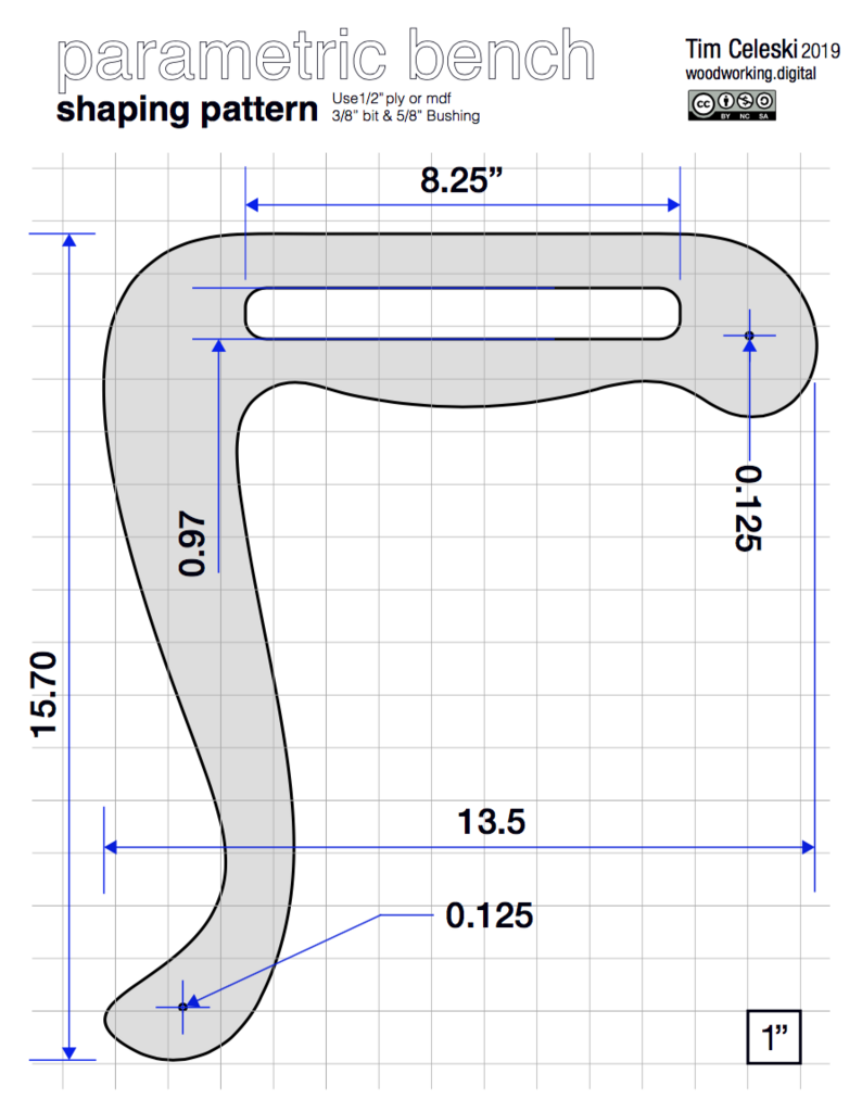
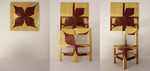
Click on the image to view the pdf.
Project hints: Making the template
One of the most important steps to successfully building the bench project is to make a very accurate template that you’ll use to shape the dozens of parts (the ribs) needed. Though the article includes a small drawing of both the template and the sample part, there’s nothing better than to start with a full-size accurate drawing. To help you create your own template and sample part, I’m including a link here to download a 1:2 scale PDF drawing of both the template and sample rib.
To make your template, start by printing out the drawings in sections at 200%, use the background grid for alignment, then tape the sections together. Once you have a full-size paper drawing, trim right up to the outside line, and using spray adhesive, attach it to a piece of 1/2” MDF or plywood for your template. Once you’ve roughed out the template and slot with a jigsaw and/or a bandsaw, use rasps and files to finesse everything right up to the lines in the drawing. Pay careful attention to the slot opening and the positions of the small holes at the foot and head of the rib. These need to be precise. Take your time to get the template right, because if it’s accurate then the 24 to 48 parts you’ll make will be perfect, too.
Simple trick to making the sample rib needed to layout the ribs on your plywood? Just make a perfect template and use it to shape your sample part.
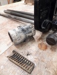
Finally, a reminder that the template is offset and is designed for using a 3/8” spiral bit mounted in a router with a short 5/8” bushing.
The Spine
As mentioned in the article, it’s important not to get too carried away with your spine design. If you make it more bumpy than smooth, your ribs will protrude in a jarring way rather than progress smoothly through a curve or bow shape. I tried a number of spine designs during project development and I found out that changes over 15-18” was about the minimum distance needed for a smooth, progressive shape change. Anything shorter and the ribs protrude in a not-so-nice way.
That said, I do encourage you to experiment with different spine shapes. There’s a lot of potential in spine and rib construction and the design of the spine is both the easiest and most dramatic way to develop new designs.
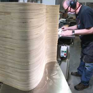
No two ways around it. There are a lot of parts involved in making this bench. And, more parts always means more sanding.
Assembly Details
Pay careful attention to the white areas in the article’s illustration that shows where to apply glue. Some of the glue will go on the previously mounted rib, most of the glue will go on the rib about to be added. In both cases, take care to keep the glue 1/4” or more away from the rib’s edge as squeeze out is nearly impossible to clean up in this project.
If you’re using a brad nailer, as I did, when attaching the bottom spacers make sure you use brads on both sides of ribs. Because your gluing end grain spacers to plywood, the glue surface is not quite enough to hold the spacers and ribs together as the bench flexes, so a solid mechanical attachment is necessary. With a little planning, I found I was able to completely hide my brads during the project. If you don’t have a brad nailer, consider screwing the ribs and spacers as an alternative.
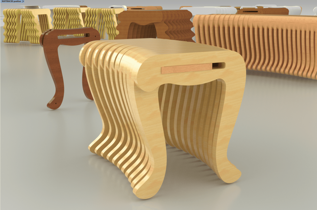
Alternate Designs
As I mentioned, spine and rib construction opens up a lot of possibilities for woodworkers to explore. Indeed, there are a lot of other rib designs other than the cabriolet leg theme I used for the project. During development, I created nearly a dozen alternative rib designs and prototypes. Most of them worked quite well, but I did find that some designs were more efficient in plywood usage than other designs. The cabriolet design was very efficient at 24 ribs per sheet of plywood, other designs yielded as low as 16/sheet. If you want to create your own designs (please do!), I suggest starting with the drawing of the cabriolet leg and use the key positions: the rib ends, the legs and the corners of the ribs as a guide to efficiency. Having a more open “L” shape is key trick for good use of materials.
I look forward to seeing what new designs Popular Woodworking readers come up for spine and rib construction. As you create your own designs, share them for all to see.
Additional Resources
- Modern Bench original article
- Modern Parametric Bench Tips and Details
- CNC the Modern Parametric Bench
- CNC machinable files at woodworking.digital
- PDF drawing of the Parametric Bench Template
- Digital Woodworking on Instagram
- Digital Woodworking YouTube Channel
- Personal Work on Instagram
Here are some supplies and tools we find essential in our everyday work around the shop. We may receive a commission from sales referred by our links; however, we have carefully selected these products for their usefulness and quality.