We may receive a commission when you use our affiliate links. However, this does not impact our recommendations.
This jig helps you easily reverse your work for base turning.
Properly finished bowls never reveal how the turner mounted them. However, traditional methods for reversing a bowl to turn the base involve a lot of fuss and bother. Cole Jaws, for example, require cranking at least 48 hex screws for each use (not to mention the aggravation of having to scrabble in the shavings for dropped screws).
Leslie Longworth must have been aggravated, too, because he did something about it. Two decades ago he conceived an ingenious self-centering scroll chuck that does the reversing job fast and elegantly. Unfortunately, it attracted little interest, perhaps because it appears complicated. His instructions were incomplete, because he was able to write only the first of two intended articles on its construction before passing away.
However, with a little imagination, the first article contains enough information to not only make his chuck but to develop it further.
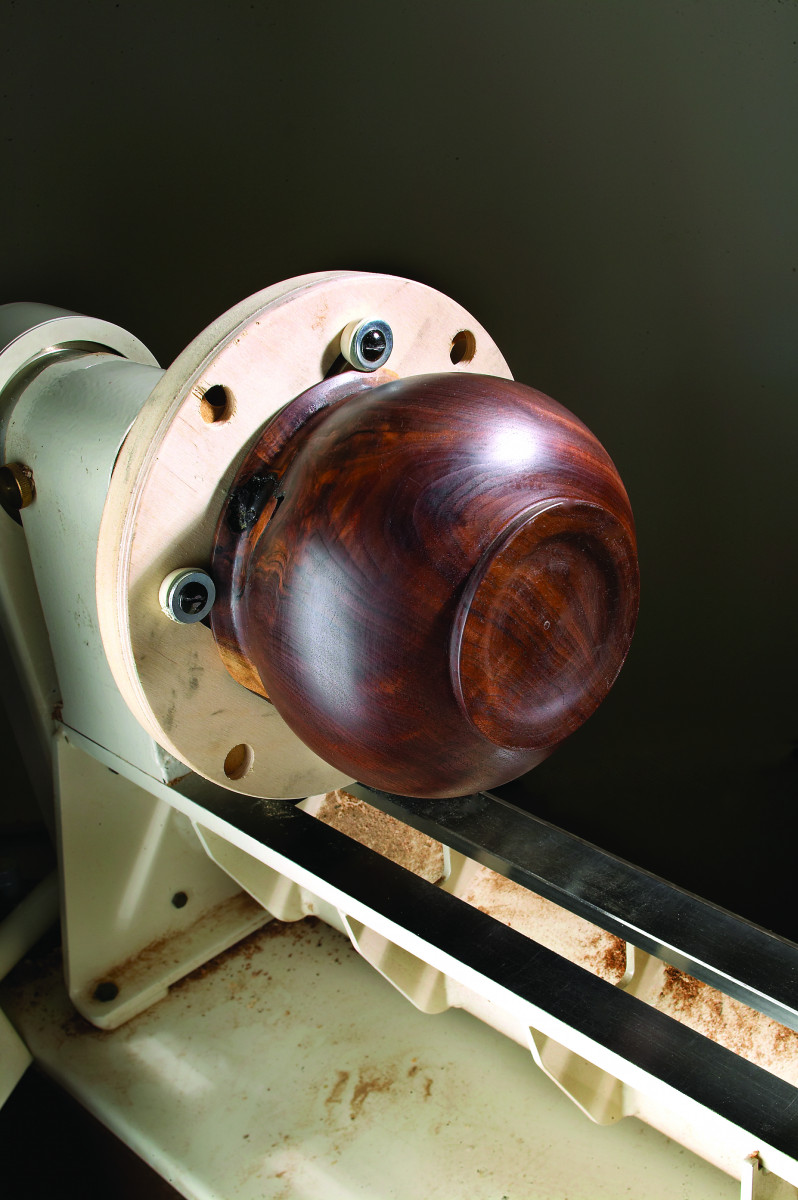
This 15″ version of the Longworth chuck has six long jaws. Here, it’s being used to hold a small spalted maple bowl.
The chuck is just a pair of counter-rotating disks. Their maximum radius is a smidgen less than the distance between the lathe’s headstock and bed. Outboard turners could size chucks to accommodate still larger work, but they should consider increasing the thickness of the materials. One further outboard consideration is that the routed arcs should be cut in the opposite direction from those described below if the headstock is not reversed such that the workpiece is rotating counterclockwise.
Some preliminary comments before starting to build:
1. Longworth’s design shows only four jaws that are not well suited to handle side pressure. I discovered that it’s just as easy to make a six-jaw chuck.
2. It’s crucial to do the following steps in order. Trust me.
3. The spinning jaws and wing nuts can hurt. A lot.
Start by cutting matching disks of 3⁄4” MDF for the back and 1⁄4” Baltic birch for the front. Other materials might work, but I know these stay flat.
The next step is choosing how to mount the chuck on the lathe. You could turn a hardwood flange to fit your scroll chuck’s jaws, and glue and screw it to the MDF disk. However, a self-mounting chuck is a convenience, so adding a small faceplate works well. It also ties up an expensive component, because removing and replacing the faceplate would soon wear the screw holes in the MDF. An alternative is a nut with the same thread as the lathe’s headstock. (See “Make the Headstock” on page 55.)
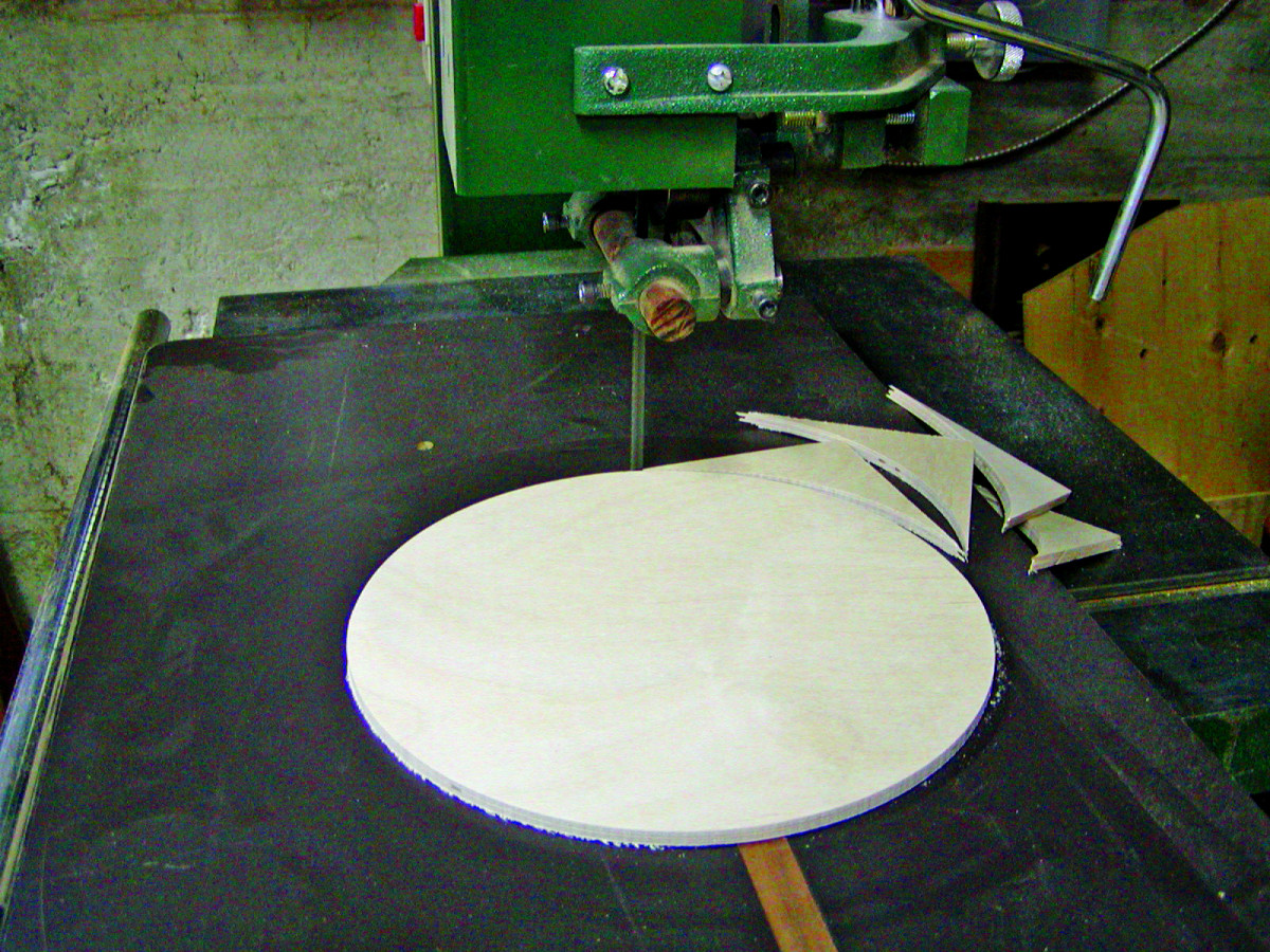
Use your band saw to cut matching disks of 3⁄4″ MDF for the back and 1⁄4″ Baltic birch for the front.
Whatever you decide, tack the front disk to the back disk with four small finishing nails set about 1⁄2” in from the rim. Mount the assembly on the lathe, true up the rim, and round the edges.
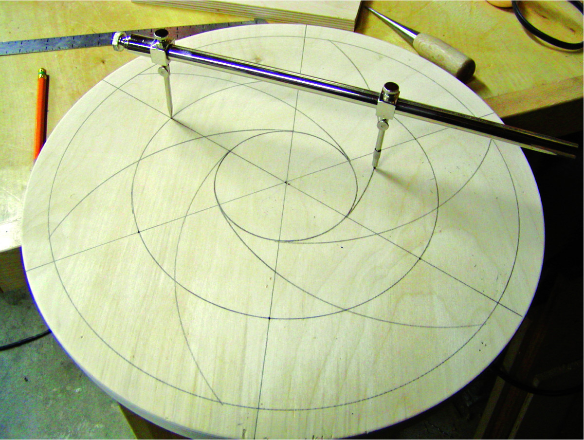
The layouts for both a four-jaw and a six-jaw chuck. (You could use a trammel for both layouts.)
 Now for the most crucial step: Use a chuck in the tailstock to drill a 1⁄16” hole through the exact center of both disks. This hole will ensure the chuck runs true after final assembly.
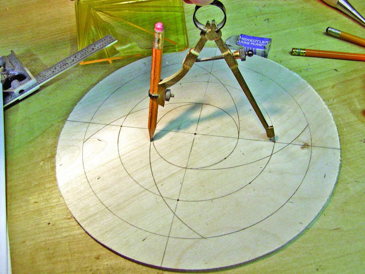
Remove the chuck from the lathe and clamp it in a vise. Draw three circles. The smallest is the diameter of your faceplate or nut, plus about an inch; the largest is the diameter of the disk less about an inch; the middle circle is centered between the other two.
At this point, if you’re making a chuck larger than about 14″, you have to decide how many jaws you want. I’ve made both, and while four are adequate, I recommend six. The photo at the bottom of the page shows the layouts for a four-jaw and a six-jaw chuck. For four jaws, draw two perpendicular lines through the center of the 1⁄16” hole you drilled earlier. For six jaws, draw three lines at 60° angles. I used drafting triangles.
Use a solid carbide upcut router bit to cut your arcs, as this will produce the cleanest cut in both plywood and MDF.
 Dimple the intersections of the diameter lines with the middle ring, and then use the dimples to draw arcs from the outer ring to the tangent of the inner ring. (Drawing these arcs helps avoid mistakes while routing.) Keep the compass set for the router jig.
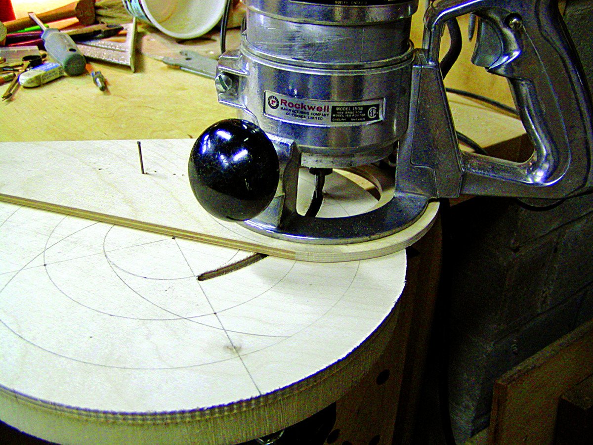
I made a circle-cutting base (photo next page) for my router out of 1⁄4” Baltic birch. The hole is 3″ in diameter for good vision, because all start and stop points are by eye. With a 1⁄4” bit in a router, set the compass pin against the edge of the bit closest to the wing on the router base, and draw a short arc on the wing. Drill a 1⁄16” hole through that arc and insert a nail as a pivot pin. Push it through so that about 1⁄2” protrudes and set it in a dimple on the disk. Push the jig flat and hammer the nail in at least 1⁄8” to ensure the jig can’t slip out of position.
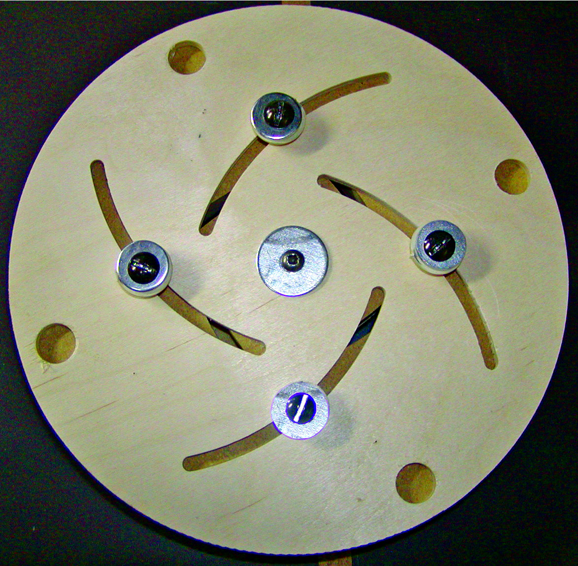
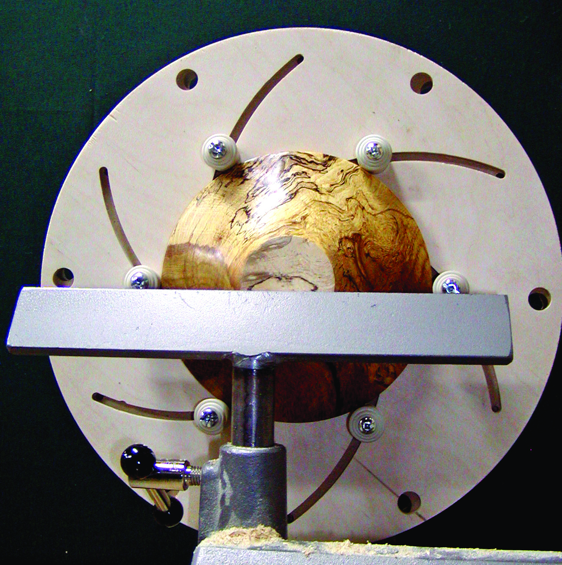
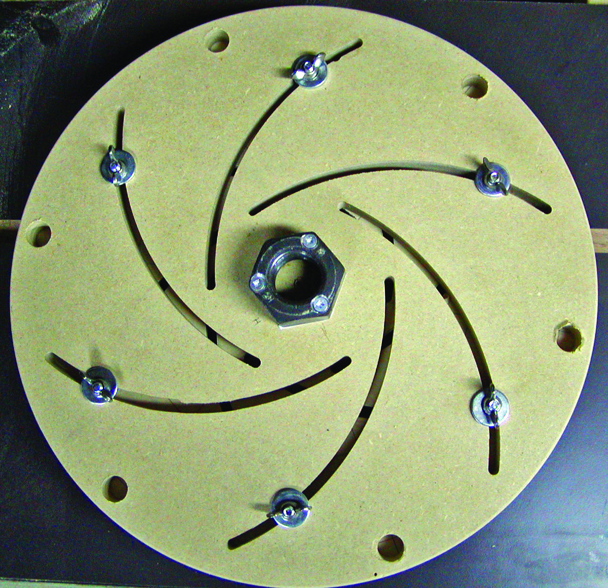
The buttons on the front of a 10″ four-jaw chuck and the wing nuts on the rear of a 15″ six-jaw chuck.
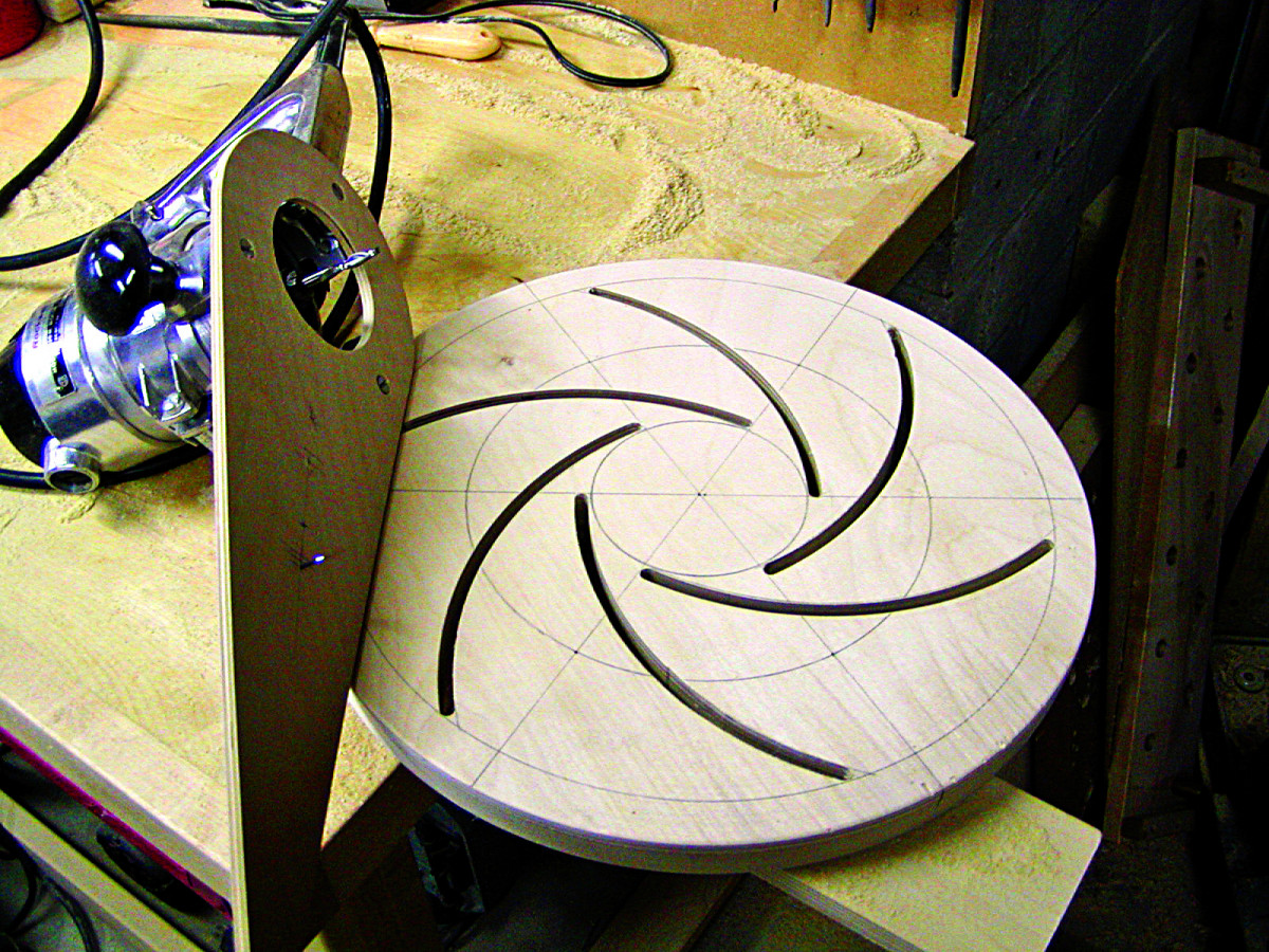
 Routing the arcs is so easy that one can become a tad complacent and make a ruinous mistake. Take your time. Begin a cut by plunging the bit partially into the work about 1″ away from an outside start point, back it up to that point –cautiously; this is a climb cut – and then pull forward to the end point. A solid carbide bit required only two gentle passes to go through both disks. Repeat until all arcs are cut. The result will look like the photo at above right.
Now drill finger holes (about 3⁄4” diameter) around the perimeter of the disk sandwich; drill four for a small chuck, and six for a large one. These provide the means to counter-rotate the disks to set the jaws.
A #10 x 1″ roundhead wood screw with an unthreaded shoulder serves as an axle, so enlarge the center hole in the front disk just enough for a snug fit on the screw shoulder. Enlarge the center hole in the back disk to the inside diameter of the screw’s thread.
Sand both faces of both disks smooth, taking particular care to get rid of any fuzz on the edges of the routed arcs. Apply a couple of well-buffed coats of paste wax to the face of the MDF disk, and to the face of the Baltic-birch disk that has the drawing on it. This will ease rotation. Now reverse the front disk and place it against the back disk so that the routed arcs cross. Drive in the axle screw, and back it off just enough to permit the front disk to rotate. This completes the chuck body.
Now for the jaws. The photos above show the buttons on the front of a 10″ four-jaw chuck and the wing nuts on the rear of a 15″ six-jaw chuck.
The jaws are made from rubber leg tips available from hardware and housewares stores. (Do not buy the vinyl versions. They do not grip.) The 5⁄8” sleeve type is best for large chucks, and also provides more reach. However, I’ve found the screw-on button type is the best choice for smaller models.
The sleeve tips require wooden inserts for attachment, so turn a dowel to 5⁄8” diameter, and cut lengths to fit inside each sleeve. Drill 1⁄4” holes lengthwise through the top of the rubber tip and the dowel. With 1⁄4” x 21⁄2” machine screws inserted through the dowels and the arcs, wing nuts and washers on the rear of the back disk make for quick and easy adjustment.
The buttons that back the sleeve tips require washers (smaller in diameter than the buttons) under the screw heads to compress the buttons against the workpiece.
Rotate the disks until the outer ends of the arcs overlap. Insert the jaws and place the washers and wing nuts loosely on the back side. Rotate the front disk again, and watch how it perfectly synchronizes all four or six jaws as they move in and out. Place a reversed bowl against the disk face, rotate the jaws until they press against the outer – or inner – edge of the bowl, tighten the wing nuts, and the whole unit is secure.
Now, retire your Cole Jaws and jam chucks.
Make the Headstock
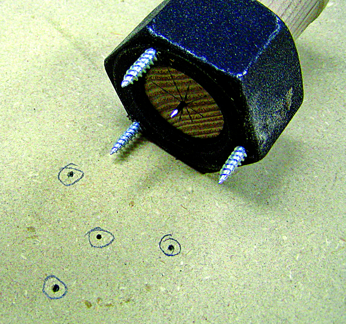
Headstocks on smaller lathes generally use standard pipe thread, and nuts are readily available. Unfortunately, for those with 1 1⁄4” headstocks, the standard 1 1⁄4” pipe thread is seven teeth per inch (TPI), so you’ll have to go to a specialty supplier for 1 1⁄4” x 8 TPI nuts. I bought several and have been using them to make a variety of faceplates. To mount them, I drill and countersink three holes through the face of the nut – the metal is soft – and use wood screws to fasten it. (Size the holes so the screws fit snugly.) A small nut has a further advantage in that the diameter of the nut/faceplate establishes the limit of inward travel for the buttons.
However, manufacturers have no need to ensure the faces are perfectly coplanar. All of mine have been off just a little, inducing wobble in the chuck. The fix is not difficult. You can put the nut on the headstock, and use a sanding disk in the tailstock to face it. Alternatively, mount the nut on the MDF disk centered as well as possible. Although this positioning is not critical, I turned a plug that will just squeeze through the nut, and drove a small finishing nail into its center. By dimpling the center of the disk, the nail will ensure the nut is centered. Tapping the three screws with a hammer marks the pilot holes.
If your nut does induce wobble, you can reduce it to almost nothing by shimming one side of the nut with a single business card. Eliminate the rest by facing the rear disk.
Here are some supplies and tools we find essential in our everyday work around the shop. We may receive a commission from sales referred by our links; however, we have carefully selected these products for their usefulness and quality.