We may receive a commission when you use our affiliate links. However, this does not impact our recommendations.
Ask ten woodworkers how to build kitchen cabinets and you’ll get eleven answers. So where do you start? At the New England School of Architectural Woodworking (NESAW), we’ve consolidated industry “best practices” to create a simple and efficient system of building cabinets that works for professionals as well as home woodworkers.
Two construction methods dominate the kitchen cabinet industry. Face frame construction is favored in the United States, but frameless construction (without face frames) is used almost exclusively in the rest of the world. Developed in Europe following World War II, frameless construction is based on efficient use of time and materials. It utilizes the 32mm (or “Euro”) system, in which line-bored holes used to connect the cabinets and install hardware and shelving are spaced in 32mm increments. Because of this system’s worldwide popularity, nearly all cabinet hardware is designed to work with it.
The cabinet-building method we teach at NESAW combines classic styling with the benefits of frameless construction and the 32mm system. In this story I’ll show how to build a base cabinet (Fig. A and Cutting List). Building this cabinet demonstrates everything you’ll need to know about the process we use, so you’ll be able to build your own high-end kitchen cabinetry without causing high-end stress.
Also in this series: Kitchen Cabinet Essentials • How to Make a Cabinet Drawer Box • How to Install A Cabinet Drawer • How to Make a Cabinet Door • How to Install a Cabinet Door • Prefinishing Plywood
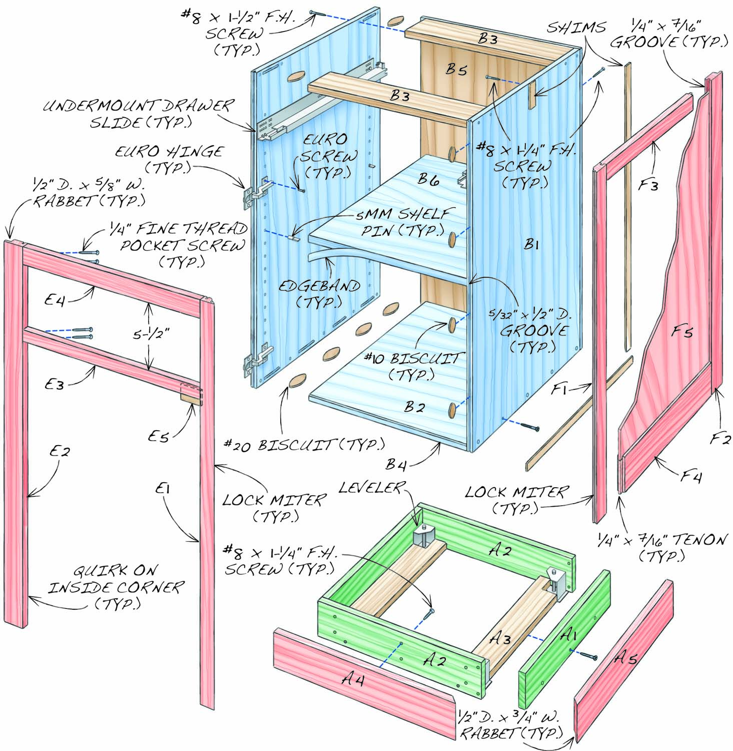
Fig. A: Base Cabinet Exploded View
Base Cutting List
|
Base Kitchen Cabinet Overall Dimensions: 34-1/2″ H x 21-1/2″ W x 24-1/2″ D (a) |
|||||
|
Section |
Part |
Name |
Qty. |
Material |
Th x W x L |
|
Base |
4″ x 19-3/4″ x 21″(d) |
||||
|
A1 |
Side |
2 |
Plywood (b) |
3/4″ x 3-1/2″ x 18-3/4″ (d) |
|
|
A2 |
Front/back |
2 |
Plywood (b) |
3/4″ x 3-1/2″ x 19″ (d) |
|
|
A3 |
Stretcher |
2 |
Plywood (b) |
3/4″ x 3″ x 18-3/4″ |
|
|
A4 |
Applied front |
1 |
Cherry |
3/4″ x 4-1/2″ x 20-7/16″ (e) |
|
|
A5 |
Applied side |
1 |
Cherry |
3/4″ x 4-1/2″ x 21-1/2″ (e) |
|
|
Carcass |
30-3/4″ x 19-3/8″ x 22-11/16″ |
||||
|
B1 |
Side |
2 |
Maple plywood (c) |
3/4″ x 22-3/16″ x 30-3/4″ |
|
|
B2 |
Bottom |
1 |
Maple plywood (c) |
3/4″ x 22-3/16″ x 17-7/8” (f) |
|
|
B3 |
Stretcher |
2 |
Maple plywood (c) |
3/4” x 4″ x 17-7/8” |
|
|
B4 |
Edging |
1 |
Maple |
1/8″ x 3/4″ x 17-7/8″ |
|
|
B5 |
Back |
1 |
Maple plywood (c) |
1/2″ x 19-3/8” x 30-3/4″ |
|
|
B6 |
Shelf |
1 |
Maple plywood (c) |
3/4″ x 21-15/16″ x 17-5/8″ |
|
|
Door |
3/4″ x 17-7/8″ x 22-3/4″ (g) |
||||
|
C1 |
Stile |
2 |
Cherry |
3/4″ x 2-5/16″ x 22-3/4″ (h) |
|
|
C2 |
Upper rail |
1 |
Cherry |
3/4″ x 2-5/16″ x 14-1/8″ (h, j) |
|
|
C3 |
Lower rail |
1 |
Cherry |
3/4″ x 3-5/16″ x 14-1/8″ (h, j) |
|
|
C4 |
Panel |
1 |
Cherry plywood |
1/2″ x 14-1/16″ x 17-15/16″ |
|
|
Drawer |
5-5/16″ x 17-11/16″ x 21″ |
||||
|
D1 |
Front/back |
2 |
Maple |
1/2″ x 4-1/4″ x 17-1/4″ (k) |
|
|
D2 |
Side |
2 |
Maple |
1/2″ x 4-1/4″ x 20-3/4″(l) |
|
|
D3 |
Bottom |
1 |
Maple plywood |
1/4″ x 16-3/4” x 20-1/2” |
|
|
D4 |
Applied front |
1 |
Cherry |
3/4″ x 5-1/2” x 17-7/8” (g) |
|
|
Face Frame |
13/16″ x 21-1/2″ x 30-3/4″ |
||||
|
E1 |
Right stile |
1 |
Cherry |
13/16″ x 1-9/16″ x 30-3/4″ (m) |
|
|
E2 |
Left stile |
1 |
Cherry |
13/16″ x 2-1/16” x 30-3/4″ (n) |
|
|
E3 |
Mid rail |
1 |
Cherry |
13/16″ x 1″ x 17-7/8″ |
|
|
E4 |
Upper rail |
1 |
Cherry |
13/16″ x 1-1/2″ x 17-7/8″ |
|
|
E5 |
Door stop |
1 |
Cherry |
1/4″ x 1-3/8″ x 1-1/4″ |
|
|
Side Panel |
13/16″x 24-1/2″ x 30-3/4″ |
||||
|
F1 |
Front stile |
1 |
Cherry |
13/16″ x 2-1/4″ x 30-3/4″ (h, m) |
|
|
F2 |
Rear stile |
1 |
Cherry |
13/16″ x 2-3/4″ x 30-3/4″ (h, n) |
|
|
F3 |
Upper rail |
1 |
Cherry |
13/16″ x 1-1/2″ x 20-3/8″ (h, j) |
|
|
F4 |
Lower rail |
1 |
Cherry |
13/16″ x 3-1/4″ x 20-3/8″ h, (j) |
|
|
F5 |
Panel |
1 |
Cherry plywood |
1/4″ x 20-5/16″ x 26-13/16″ |
|
|
Notes: (a) Width and depth dimensions include 1/2″ scribe allowances; may be more or less, depending on how much the wall is out of plumb. (b) Any type of venee- core plywood. (c) Pre-finished veneer-core plywood. (d) Width is nominal; it varies depending on how much the floor slopes. (e) Includes 1/2” in extra width and length for scribe allowance. (f) Width includes 1/8” front hard maple edging (B4). (g) Size to exactly fit the opening, then trim to leave 3/32” gaps all around. (h) One edge has 1/4″ x 7/16″ groove. (j) Length includes 7/16″ long tenons on both ends. (k) Under-mount slides require that drawer box width is 5/8″ shorter than the opening’s length. (l) Length is dependent on your dovetail jig; overall finished drawer box length must be exactly 21”. (m) One edge is mitered. Cut E1 and F1 side-by-side from the same piece of wood, so the grain wraps around the mitered corner. Mark both pieces to keep their original orientation. (n) Includes 1/2” in extra width for scribe allowance; may be more or less, depending on how out of plumb the wall is. (p) Oversize in width and length; cut and scribe to fit. |
|||||
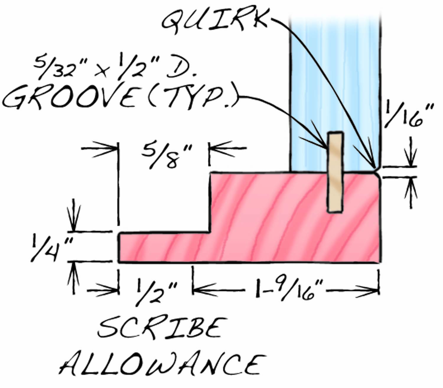
Fig. B: Top View, showing quirk.
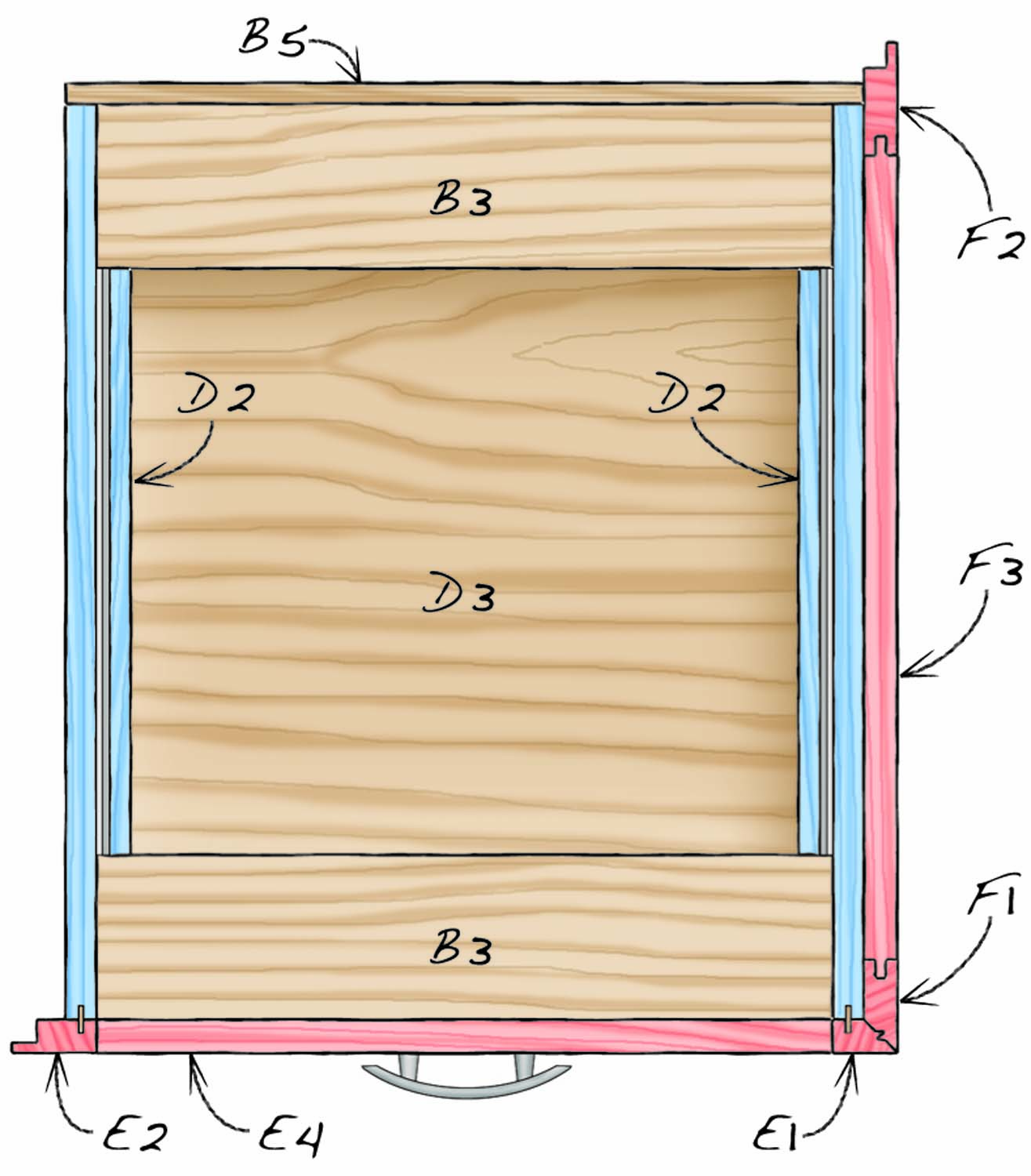
Fig. B: Top View, showing scribe allowance
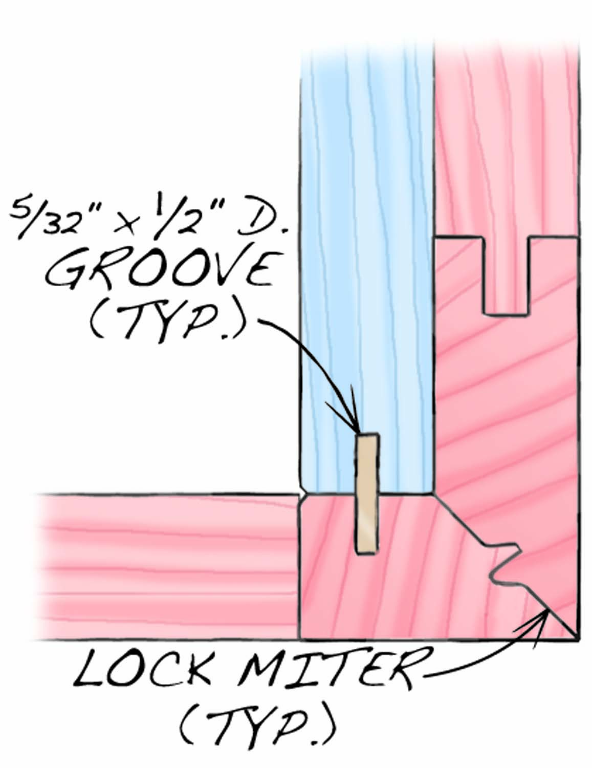
Fig. B3: Top View, showing mitered corner.
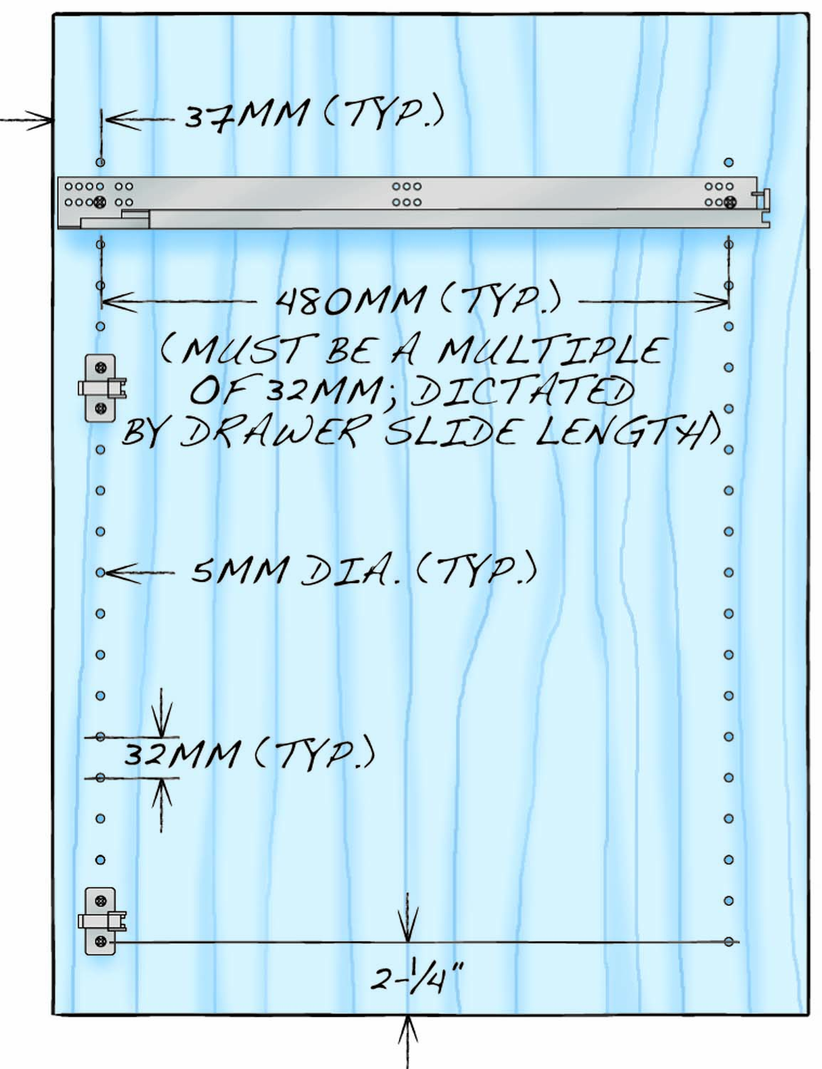
Fig. C: System Hole Layout
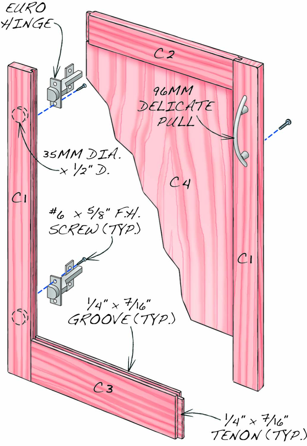
Fig. D: Door
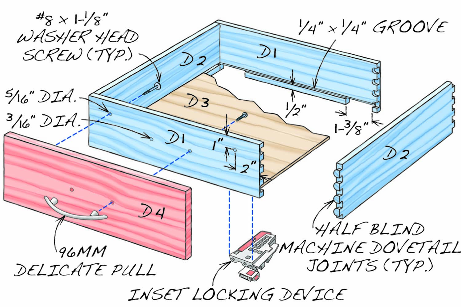
Fig. E: Drawer
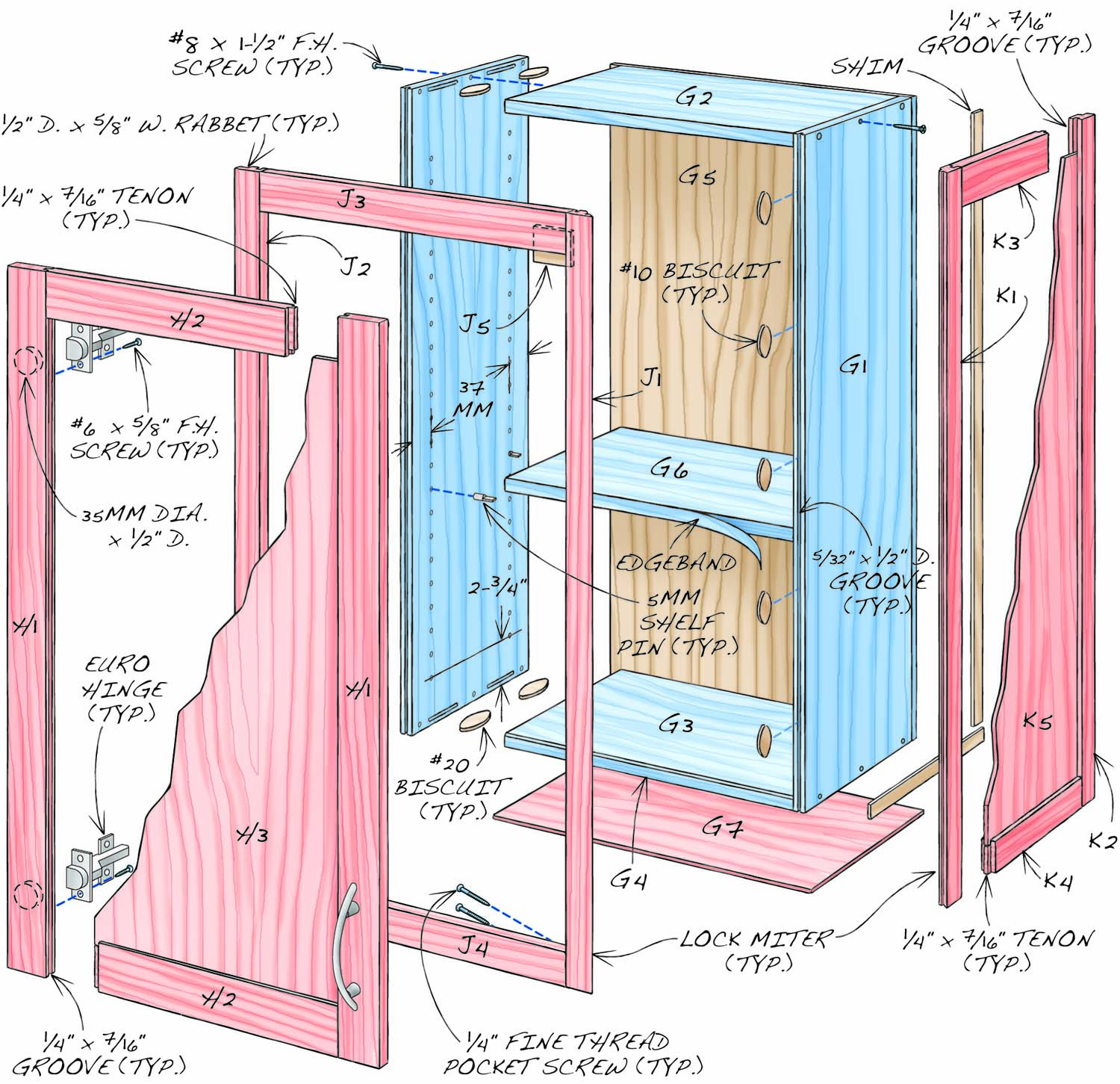
Fig. F: Upper Cabinet Exploded View
Upper Cabinet Cutting List
|
Upper Kitchen Cabinet Overall Dimensions: 36″ H x 21-1/2″ W x 13-1/2″ D (a) |
|||||
|
Section |
Part |
Name |
Qty. |
Material |
Th x W x L |
|
Carcass |
34-13/16″ x 19-3/8″ x 11-15/16″ |
||||
|
B1 |
Side |
2 |
Maple plywood (c) |
3/4″ x 11-7/16″ x 34-13/16″ |
|
|
B2 |
Top |
1 |
Maple plywood (c) |
3/4″ x 11-7/16″ x 17-7/8” |
|
|
B3 |
Bottom |
2 |
Maple plywood (c) |
3/4″ x 11-7/16″ x 17-7/8” (f) |
|
|
B4 |
Edging |
1 |
Maple |
1/8″ x 3/4″ x 17-7/8″ |
|
|
B5 |
Back |
1 |
Maple plywood (c) |
1/2″ x 19-3/8” x 34-13/16″ |
|
|
B6 |
Adj. Shelf |
2 |
Maple plywood (c) |
3/4″ x 11-3/16″ x 17-5/8″ |
|
|
B7 |
Skin |
2 |
Cherry plywood |
1/4″ x 12-3/4″ x 20-7/8″ (p) |
|
|
Door |
3/4″ x 17-7/8″ x 32-7/16″ (g) |
||||
|
C1 |
Stile |
2 |
Cherry |
3/4″ x 2-5/16″ x 32-7/16″ (h) |
|
|
C2 |
Rail |
2 |
Cherry |
3/4″ x 2-5/16″ x 14-1/8″ (j) |
|
|
C3 |
Panel |
1 |
Cherry plywood |
1/2″ x 14-1/16″ x 28-5/8″ |
|
|
Face frame |
13/16″ x 21-1/2″ x 36″ |
||||
|
E1 |
Right stile |
1 |
Cherry |
13/16″ x 1-9/16″ x 36″ (m) |
|
|
E2 |
Left stile |
1 |
Cherry |
13/16″ x 2-1/16” x 36″ (n) |
|
|
E3 |
Upper rail |
1 |
Cherry |
13/16″ x 2″ x 17-7/8″ |
|
|
E4 |
Lower rail |
1 |
Cherry |
13/16″ x 1-9/16″ x 17-7/8″ |
|
|
E5 |
Door stop |
1 |
Cherry |
1/4″ x 1-5/8″ x 1-1/4″ |
|
|
Side panel |
13/16″x 13-1/2″ x 36″ |
||||
|
F1 |
Front stile |
1 |
Cherry |
13/16″ x 1-9/16″ x 36″ (h, m) |
|
|
F2 |
Rear stile |
1 |
Cherry |
13/16″ x 2-1/16″ x 36″ (h, n) |
|
|
F3 |
Upper rail |
1 |
Cherry |
13/16″ x 2″ x 10-3/4″ (h, j) |
|
|
F4 |
Lower rail |
1 |
Cherry |
13/16″ x 1-9/16″ x 10-3/4″ (h, j) |
|
|
F5 |
Panel |
1 |
Cherry plywood |
1/4″ x 10-11/16″ x 33-1/4″ |
|
|
Notes: (a) Width and depth dimensions include 1/2″ scribe allowances; may be more or less, depending on how much the wall is out of plumb. (c) Pre-finished veneer-core plywood. (f) Width includes 1/8” front hard maple edging (B4). (g) Size to exactly fit the opening, then trim to leave 3/32” gaps all around. (h) One edge has 1/4″ x 7/16″ groove. (j) Length includes 7/16″ long tenons on both ends. (m) One edge is mitered. Cut E1 and F1 side-by-side from the same piece of wood, so the grain wraps around the mitered corner. Mark both pieces to keepthier original orientation. (n) Includes 1/2” in extra width for scribe allowance; may be more or less, depending on how out of plumb the wall is. (p) Oversize in width and length; cut and scribe to fit. |
|||||
Efficient Construction
As you can see, the cabinet actually consists of four separate components, a base (called a “ladder frame”), a box (the “carcass”), and a face frame and a side panel (the “facing”). This construction method is very efficient. Building the ladder frame and carcass separately allows getting six full carcass sides from a sheet of plywood. Leveling the ladder frame is easy, because there’s no cabinet to get in the way. Once the frame is leveled, the carcass simply sits on top and is anchored to the wall. For runs of cabinets—the heart of most kitchen cabinetry—you just build plywood boxes, fasten them together and cover them. And you only have to build a single ladder frame for each run.
Another key feature is that the carcass sides are flush with inside edges of the face frame. This allows using Euro hinges and drawer slides without the time-consuming task of building out the sides flush with the face frame. Note also that there’s no lower face frame rail. This allows using the carcass bottom as a doorstop and provides more space inside the cabinet (where every inch counts). The cabinet’s 1/2″ thick back adds extra strength and rigidity and allows anchoring the cabinet by screwing directly through the back into the wall.
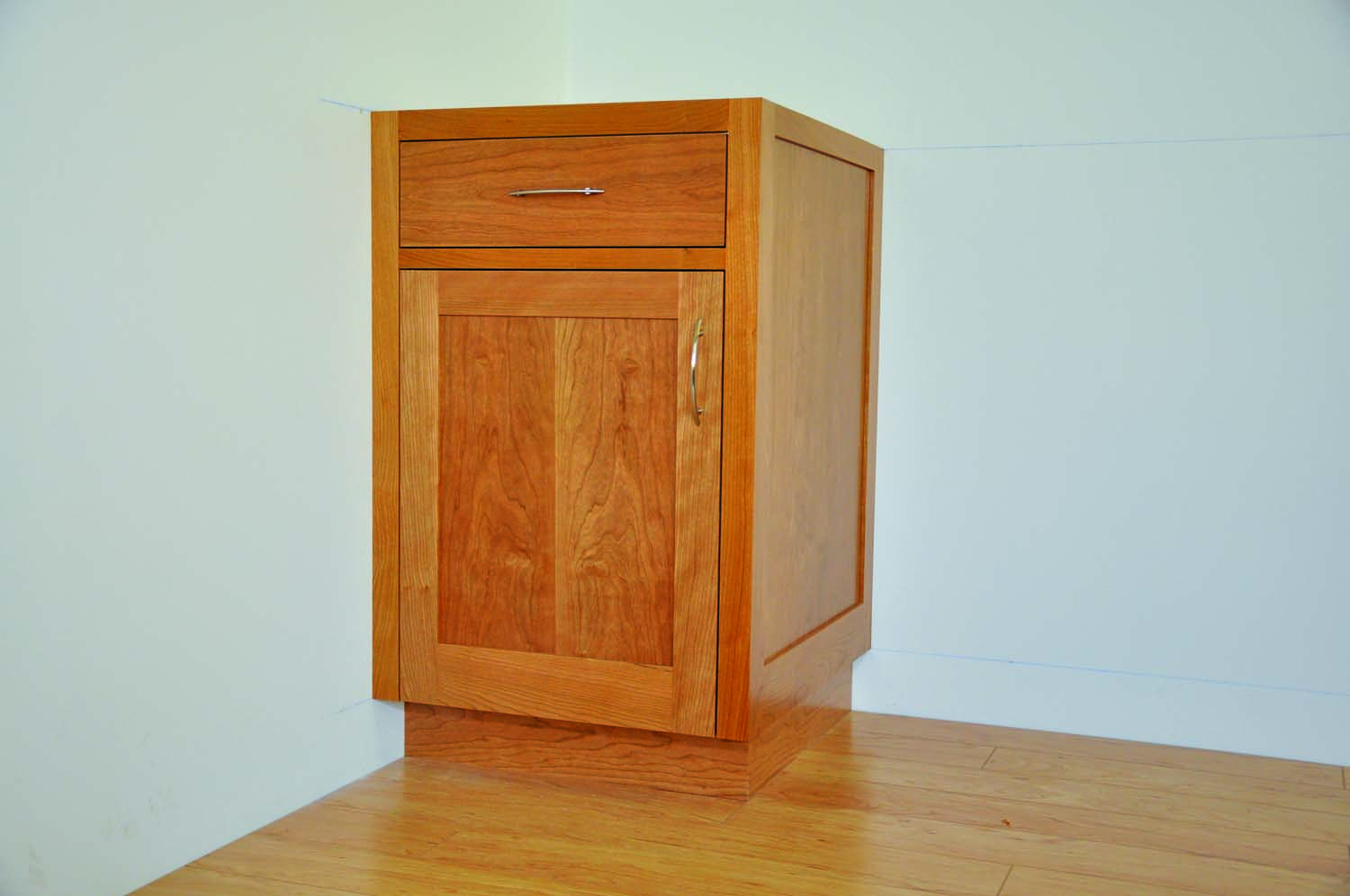
Standard kitchen base cabinets are 24″ deep and 36″ high to the top of the countertop. Our sample cabinet is 34-3/4″ high, which assumes a 1-1/4″ thick countertop top; you can modify the height of the cabinet to accommodate a different countertop thickness.
Start with the Lumber
Select boards with the straightest grain for the door stiles and rails (C1–C3). Rough mill this stock and sticker it for as long as possible before milling it to final thickness and width. Milling in stages allows the wood to stabilize in your shop environment. It’s very important that the doors stay flat; using straight grain lumber, milling it in stages, and letting it rest in between helps accomplish this goal.
Choose boards with the next-straightest grain to use for face frames and side panel frames—the appearance of wild-grained parts in the frames may detract from the panels or doors they enclose. This stock should also be milled in stages with a resting period.
Mill the face frame and side panel parts (E1–E4; F1–F4) to final thickness and width, but leave them oversize in length. Note that these parts are 13/16″ thick and that the stiles for each assembly are different widths. The extra thickness allows placing a bumper between the 3/4″ thick door and the cabinet to ensure the door closes flush with the face frame. The two wider stiles in each assembly include 1/2″ scribe allowances that allow cutting them to match the profile of an uneven wall. The ability to incorporate scribe allowances that allow you to seamlessly fit cabinets to the walls is one of the many advantages of building your own cabinets.
Build the Base
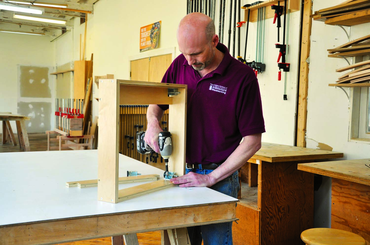
Photo 1. Start by assembling the cabinet’s base. Separating the base from the cabinet simplifies construction, eases installation and makes efficient use of materials. Screw together the box, mount the levelers and then install the stretchers.
The ladder base (so called because longer versions contain multiple stretchers that resemble the rungs of a ladder) will be covered by solid wood (A4 and A5), so you can build it using nearly any 3/4″ thick veneer core plywood. A standard toe kick is 4″ high, so cut the base front, back, sides and stretchers (A1-A3) narrower, as necessary, to accommodate shimming to an out-of-level floor. (In this case, they’re sized at 3 1/2″). Screw the base together after pre-drilling for #8 x 1-1/2″ screws; no glue is necessary. I like to install levelers in each corner of the base to make installation easier and faster (Photo 1). If you install levelers, you’ll have to notch the stretchers. Cut the base’s applied front and side parts (A4 and A5), oversize in length for now—they’ll be cut to final width and length during installation. Rout a 5/8″ x 1/2″ rabbet in the bottom edge of each part to make it easier to scribe to the floor.
Pre-finished Plywood
We use pre-finished plywood for carcasses so we don’t have to spend time finishing the insides of our cabinets. This is particularly important if you are spray finishing because you don’t have to drag the assembled carcasses back and forth to the spray room. It also eliminates overspray and blowback problems that can crop up when spraying cabinet interiors. Pre-finished maple plywood is less expensive than higher grades of plywood and the finish is very durable. If you can’t find pre-finished plywood, or want to use another species for the cabinet interiors, you can still pre-finish it.
Cut all the Parts
Start by breaking down the plywood and cutting the sides (B1), bottom (B2) and stretchers (B3) to size. At this point, leave the bottom and sides oversized in both width and length, and the stretchers oversized in length. Glue 1/8″ thick solid wood edging (B4) in the same species as your plywood to the front edge of the bottom; this edging will be exposed when the door is open and serves as a door stop when it closes. Thin veneered edge banding won’t provide sufficient protection.
Trim the edging flush with the face of the plywood on both the top and bottom, taking care not to damage the finish. Then rout a 45º bevel on its top edge to avoid damage caused by putting items in and out of the cabinet. The bevel should start exactly at the glue joint between the edging and the plywood. Apply several coats of wipe-on polyurethane to the edging before you assemble the carcass.
Cut the carcass bottom, sides, and stretchers to final dimensions along with all of the face frame and side panel parts. The face frame rails (E3 and E4) have to be exactly the same length as the carcass bottom and stretchers (B2 and B3), and the face frame and side panel stiles (E1 and E2; F1 and F2) are exactly the same length as the cabinet sides (B1), so it makes sense to cut them all at the same time, using the same stops.
Cut the side panel rails (F3 and F4) to final dimensions now, too. Their length, as stated in the cutting list, includes a 7/16″ tongue at both ends. Then use a stile-and-rail set to rout tongue-and-groove joints in the side panel’s stiles and rails. Rout the grooves first, then the tongues. The set I use adjusts to fit the thickness of the plywood panel.
Mill Quirks, Grooves and Holes
Clearly mark the carcass sides and stretchers, indicating left and right sides, and the front and top edges. Using a 45º chamfer bit, rout a tiny bevel (about 1/32″ wide) on the inside front edge of the carcass sides and the inside edge of the face frame stiles (Fig. B). This detail, called a “quirk,” disguises any misalignment when the face frame is glued to the carcass.
Next, use a router table equipped with a 5/32″ wing cutter to rout full-length grooves in the front edges of the carcass sides and in the backs of the face frame stiles. You’ll use these grooves to align the face frame with the carcass during glue up. Size the depth of the grooves for #10 biscuits and reference off of the inside face of both pieces to ensure proper alignment.
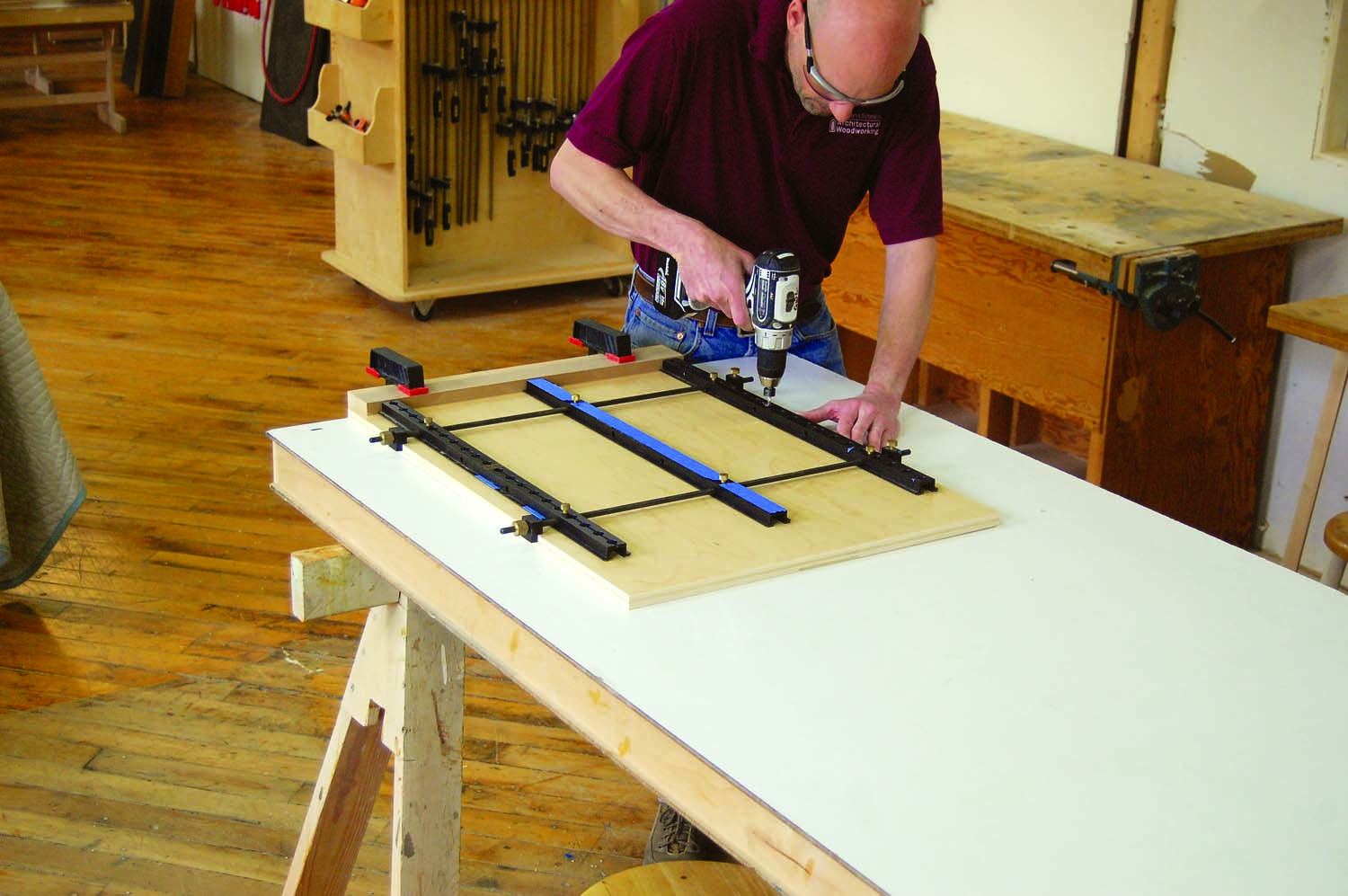
Photo 2. Line-bore 5mm holes in the cabinet sides. These cabinets are based on the 32mm system. Clamp on a 2-1/4″ spacer to index the jig, so the holes are always consistently offset from the bottom edge on both sides.
The 32mm system holes are used to mount the hinge plates, drawer slides and shelf pins. For the hardware to work properly you need to follow a few basic rules, which include drilling the front row of holes 37mm from the carcass front and the back row of holes a multiple of 32mm from the front row (480mm in this case; Fig C). It’s best to keep your layout in metric units. I prefer to use a jig such as the Veritas 32 Cabinetmaking System to drill the holes, especially when I’m building a lot of cabinets (Photo 2).
Assemble the Carcass
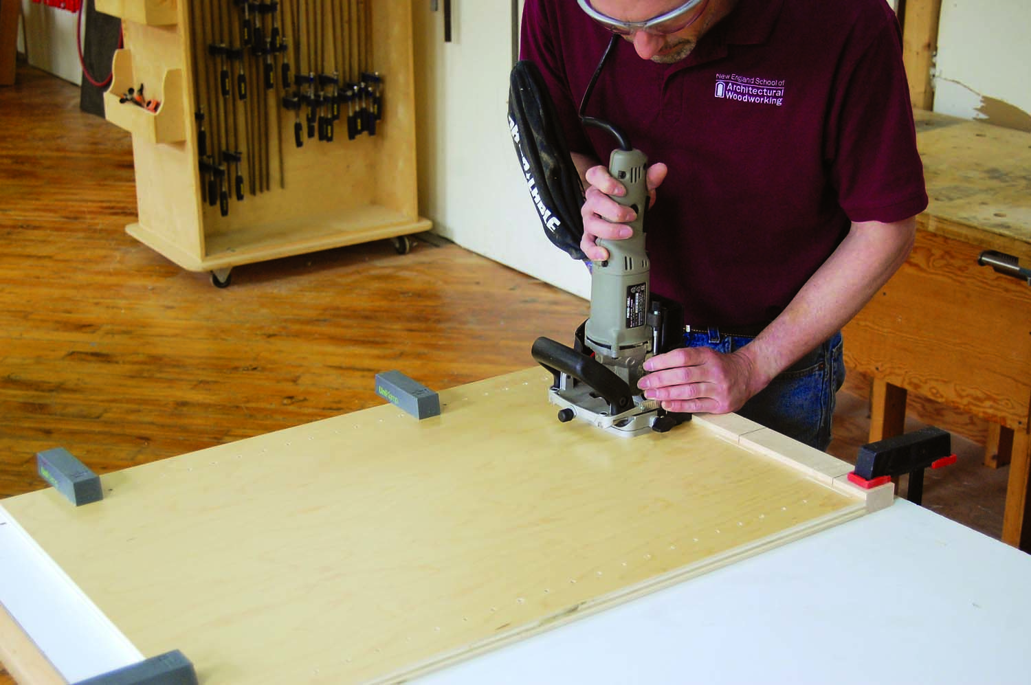
Photo 3. Cut biscuit slots in the face of the cabinet sides using a stop marked with the slot locations to register the biscuit joiner. Make sure to hold the cabinet side snug against the stop.
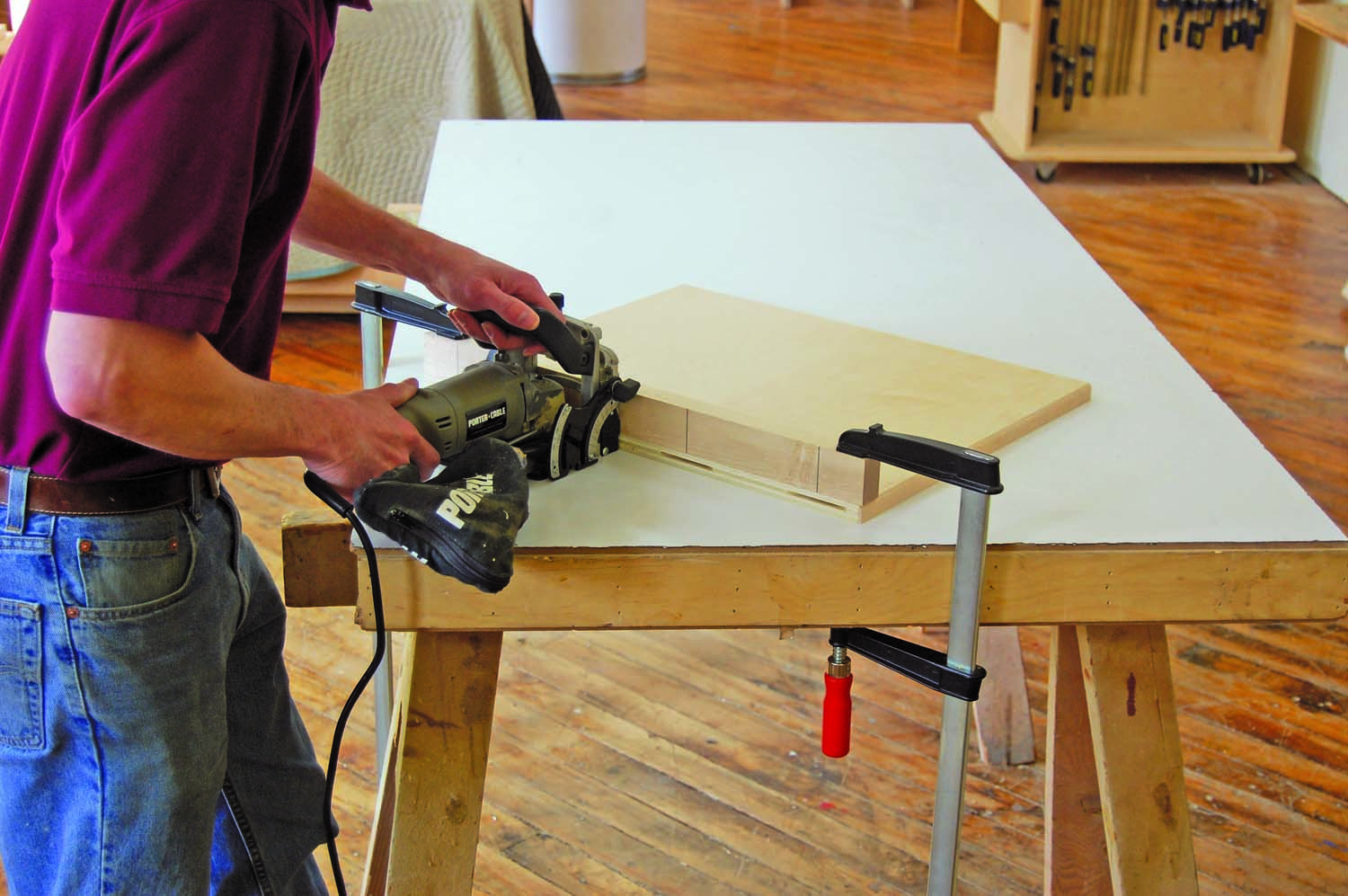
Photo 4. Cut matching biscuit slots in both edges of the carcass bottom, using the same marked stop. Make sure the bottom is firmly clamped to the table to avoid alignment issues.
The carcass assembles with butt joints, using biscuits or dominoes for positioning and screws for strength. Mill #20 biscuit slots or 5 mm x 30 mm domino mortises in the face of the carcass sides (Photo 3). Mill matching slots in the ends of the stretchers and bottom (Photo 4). Use four biscuits or five dominos to fasten the bottom, with one centered in both ends of each stretcher. Per Architectural Woodwork Institute (AWI) standards, locate the biscuit slots a maximum of 2″ on center from the edge of the side and no more than 6″ apart.
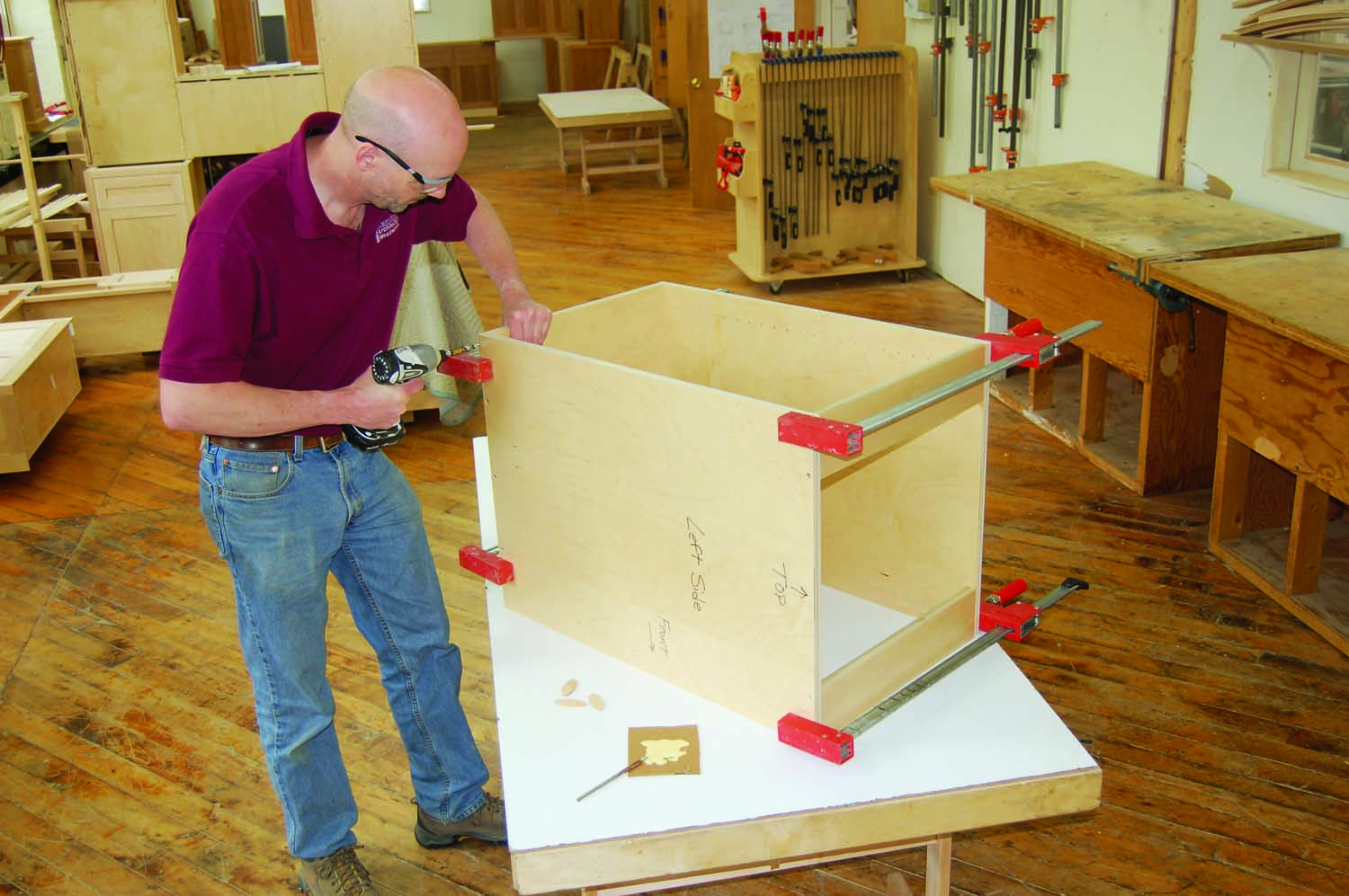
Photo 5. Screw the cabinet together after applying glue and installing the biscuits. Pre-drill the screw holes to avoid splitting the plywood and make sure the cabinet is square.
Mark the biscuit locations on the outside of the carcass sides. Then dry-assemble and clamp the carcass while it’s laying on its back on a flat surface. Make sure all of the joints come together and are flush. Then pre-drill countersunk holes for #8 x 1-1/2″ screws in the sides to connect the bottom and stretchers, making sure to avoid the biscuit locations. Disassemble the carcass and apply glue to the biscuits. Then reassemble, clamp and screw the carcass together (Photo 5). Once the screws are in, immediately remove the clamps and install the back (B5). Check for square by measuring the diagonals of the carcass’s front opening—they should be within 1/16″ of each other, preferably closer. Fasten the back using #8 x 1-1/4″ screws every 4″ on center. This is particularly important when building an upper cabinet, as the back is what supports the cabinet when it’s fastened to the wall.
Install iron-on maple edgeband on the adjustable shelves (B6) before cutting them to final dimensions.
Allow for Scribing
The face frame and side panel each contain one stile that’s wider than the other by 1/2″—a typical scribe allowance—so you can cut the stile to perfectly match a wall that isn’t straight. To determine just how much width to add for a scribe allowance, it’s important to check the wall that the cabinet will attach to. If the wall is out more than 1/2″ from top to bottom, you’ll have to add that much more width to the stile. Make sure to add at least 1/4″ more width than you think you’ll need—it’s better to be conservative than not have enough.
Rabbeting the scribe allowance eases installation by leaving much less material to remove (Fig. B). Rout the rabbet 1/8″ wider than the scribe allowance you’ve added (5/8″ for a 1/2″ scribe, for example). When you cut the rabbet, leave the tongue that remains on the face about 1/4″ thick.
Rout the rabbet in the back edge of the face frame’s extra-wide left stile (E2) now, prior to assembly. However, to make clamping easier during glue-up, wait until the side panel has been glued together to rout the rabbet in its extra-wide rear stile (F2).
Rout Lock Miters
Whenever the face frames and side panels meet, I use a miter joint. This gives the cabinets the look of high-quality furniture. With a butt joint, it’s difficult to get a pleasing grain match. But with a mitered joint, I can cut both stiles from the same piece of wood and wrap the grain around the corner.
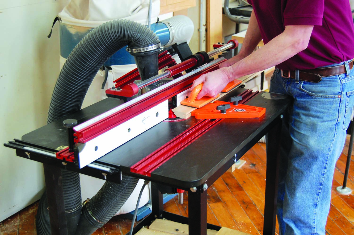
Photo 6. Mill lock miter joints in the adjacent face frame and side panel stiles. Using miters to join the cabinet’s facing components creates beautiful seamless corners that are a hallmark of fine cabinetry.
Cut the long miters on the router table, using a lock miter bit (Photo 6). With a lock miter bit, you must run one piece horizontally and one vertically. In this case, run the face frame stile (E1) vertically. This will make the clamping process a bit easier, down the road. When a lock miter bit is properly set up, you don’t need to change the fence or bit height when you switch pieces.
Assemble the Facing
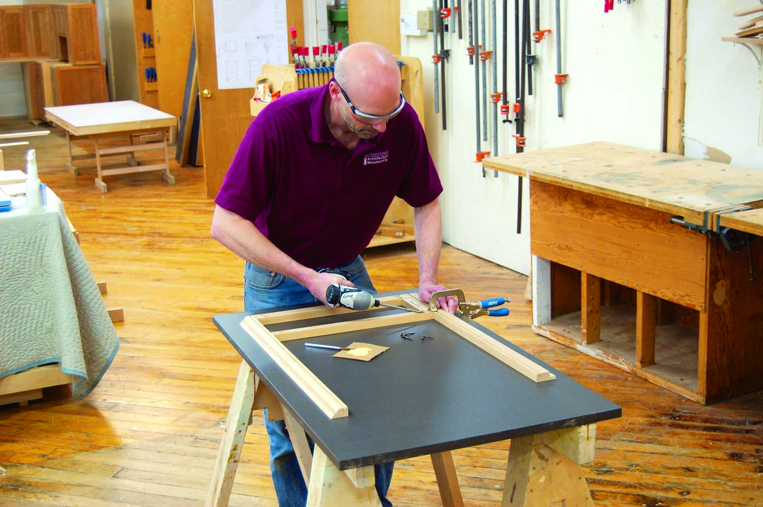
Photo 7. Assemble the face frame with glue and pocket screws. Clamp the frame to a flat surface to ensure good alignment. Take care not to damage the lock miter. Note the rabbeted scribe allowance.
Assemble the face frame using 1-1/4″ fine-thread pocket screws, taking care not to damage the lock miter (Photo 7).
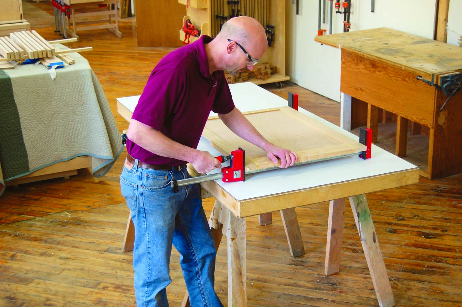
Photo 8. Glue together the side panel. Protect its delicate lock-mitered edge by using a spacer and shop-made clamping blocks with the reverse profile. Rabbet the scribe allowance in the extra-wide back stile after glue-up.
Glue and clamp the side panel assembly using shop-made clamping blocks and a spacer to protect the lock-mitered edge (Photo 8). The blocks are the mirror image of the lock miter. The spacer, added behind, keeps the clamps away from the miter’s knife edge. After the glue has dried, rabbet the scribe allowance in the rear stile (F2). Waiting to mill this rabbet after glue-up makes clamping easier. Remove the squeezed-out glue, but do not sand the side panel or the face frame until they are glued together, to avoid damaging the lock miter.
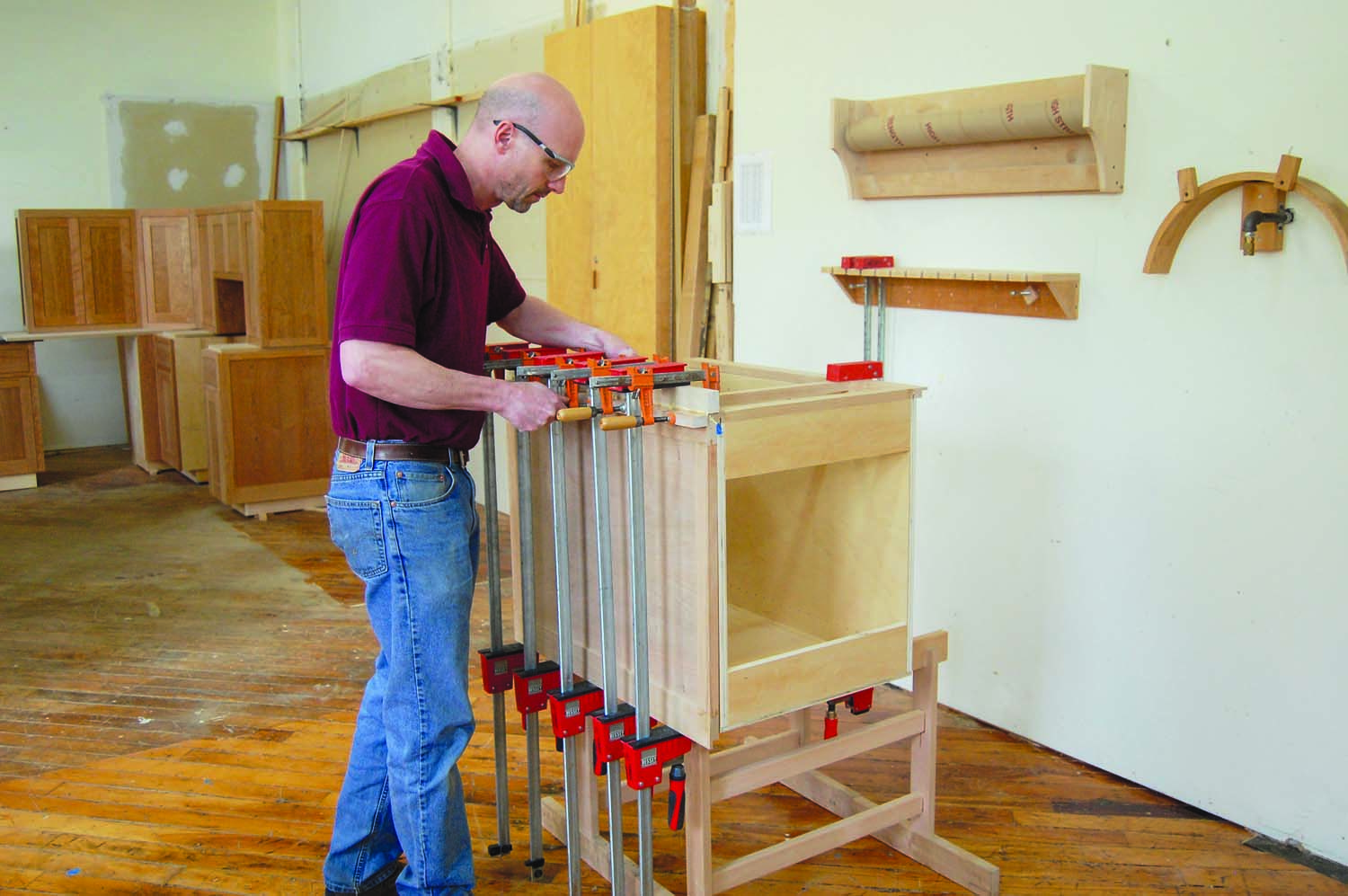
Photo 9. Glue the lock miter joint between the face frame and the side panel. Use the carcass as a positioning guide and cauls to ensure a tight-fitting joint. Tape the carcass so it doesn’t stick to the glue-up.
Use the carcass as a convenient jig to support both pieces when you glue the lock miter joint between the face frame and the side panel (Photo 9). Tape the front corner of the carcass so squeezed-out glue doesn’t adhere the glued-up assembly. Use clamping cauls from both directions to ensure a tight joint.
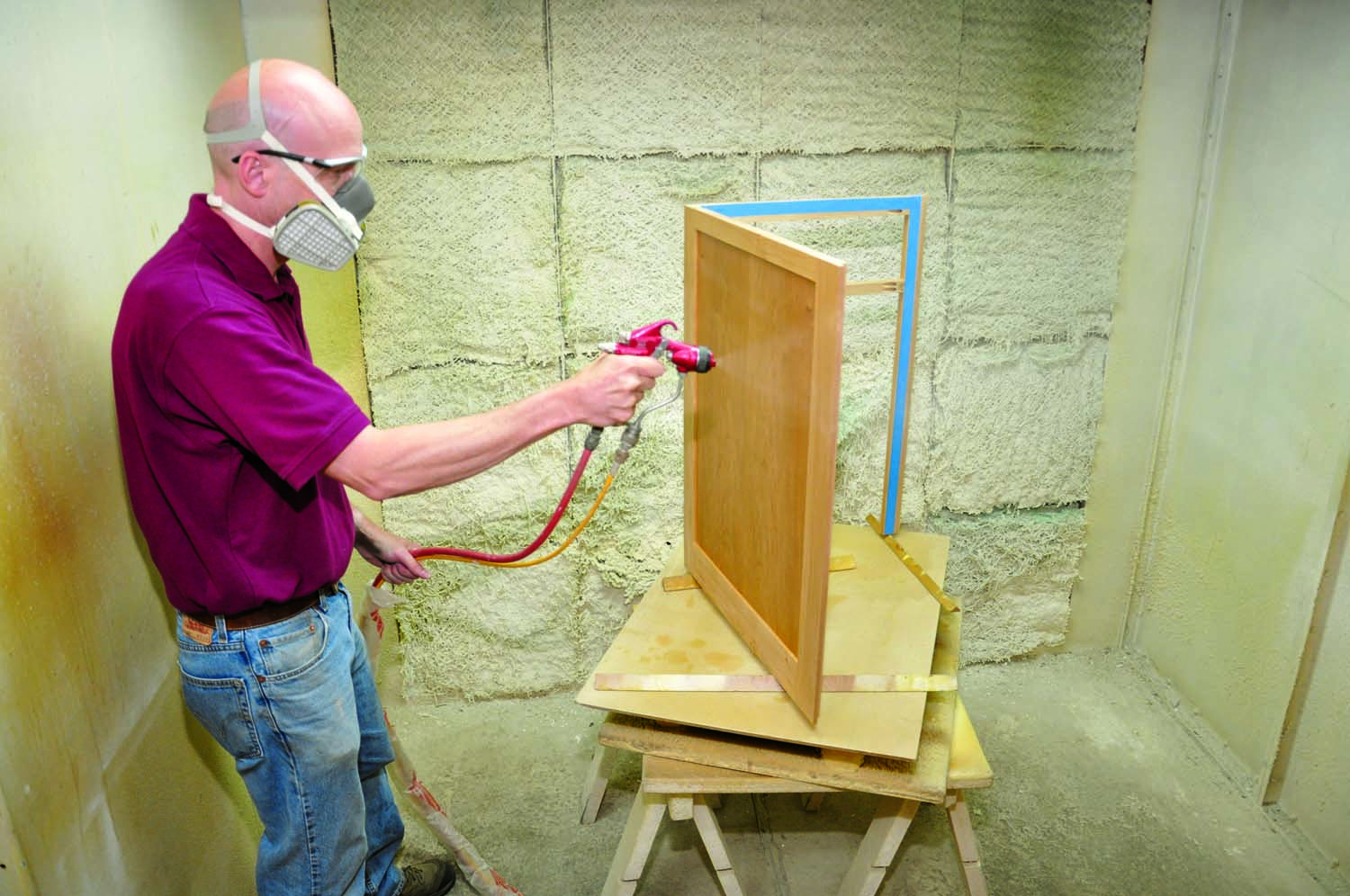
Photo 10. Sand and finish the cabinet’s facing. Facings for end cabinets, as shown here, consist of face frames and side panels. Facings for interior cabinet runs consist of face frames only.
When the glue has dried, finish-sand the facing assembly to prepare it for finishing. Tape off the back of the face frame where it will contact the carcass, to ensure good glue adhesion later. Then apply the finish (Photo 10). At NESAW, we spray one coat of Zinsser SealCoat dewaxed shellac followed by two coats of ML Campbell Aqualente water-based lacquer.
Attach the Facing
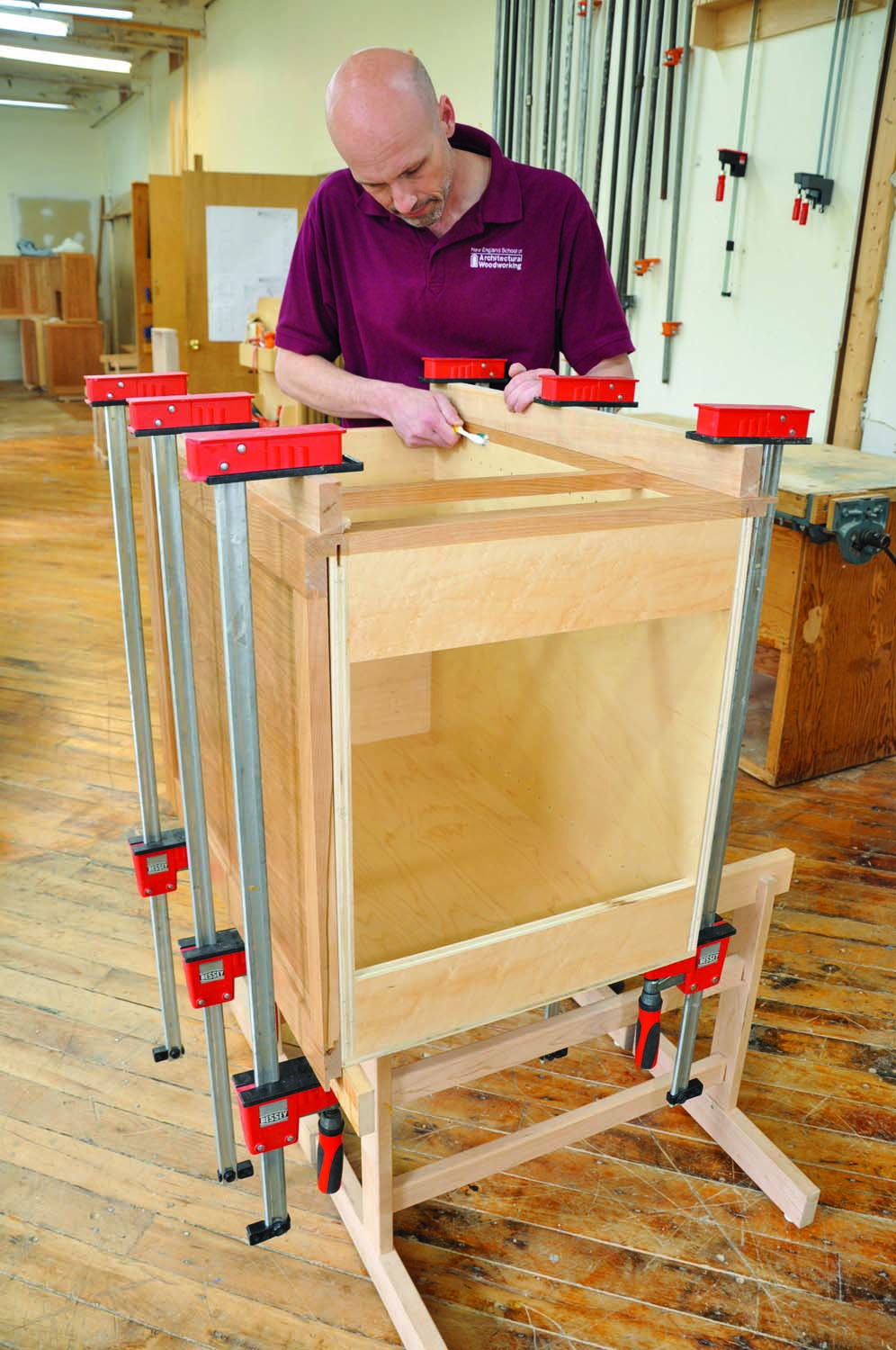
Photo 11. Glue the pre-finished facing to the carcass after installing biscuits in the grooves to align the parts. On two-part facings like this one, glue only the face frame. Then remove any squeezed-out glue.
After the finish has dried, install biscuits in the routed grooves in the front of the carcass. Use these biscuits to align the facing assembly when you glue it on (Photo 11). Before clamping, apply tape to the clamping cauls and make sure they’re smooth and free of debris to avoid damaging the finish. After clamping, immediately remove squeezed-out glue from the quirks, the tiny bevels in the joints between the face frame stiles and the carcass sides. A toothbrush works great for this.
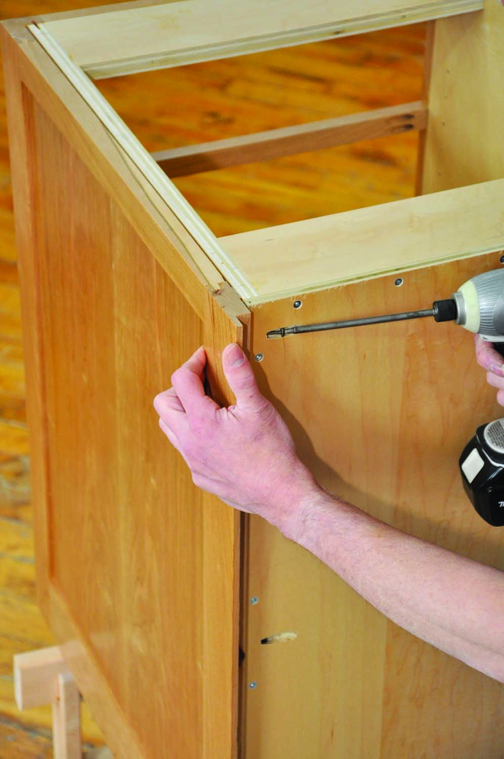
Photo 12. Fasten the side panel at the back, using pocket screws along its entire length. Install a full-length shim to keep the panel parallel with the carcass.
Install shims sized to maintain an even gap along the panel’s length. Then attach the side panel to the carcass, using 1-1/4″ fine-thread pocket screws through the back and along the bottom edge (Photo 12). At the top edge, attach the side panel at the midpoint of the carcass. Install a shim and then screw directly through the carcass into the panel’s upper rail. Use #8 x 1-1/4″ screws.
Glue and screw a door stop (E5) to the back of the face frame’s mid rail, so it protrudes 3/8″ into the upper right corner of the door opening. Stopping the door at both the top and bottom keeps the door from warping due to the force of the European hinges. Apply finish to the door stop and any areas on the back of the face frame that weren’t finished earlier.
Build the Door
Mill the door stiles and rails (C1–C3, Fig. D) to final dimensions. Note that the bottom rail is wider than the top rail. This helps to “ground the cabinet,” since there is no bottom face frame rail. Size these parts so the glued-up door will be the same size as the opening. Use the same stile and rail cutter you used for the side panel to cut the tongue and groove joints. Cut the panel (C4) and glue up the door.
Fit the door to the opening in the cabinet and then install it using Euro-style adjustable cup hinges. Remove the door to sand and finish it. Then install the pull.
Build the Drawer
The drawer consists of a dovetailed box with an applied front (D1–D4, Fig E). It rides on drawer slides that hide under the box, so they’re invisible when the drawer is open. I use a dovetailing jig to make the drawer box.
The drawer box must be accurately sized to accommodate the under-mount slides. (Always consult the manufacturer’s instructions before building your drawers and stick as closely as possible to the recommended dimensions.) The 21″ Blum slides we’re using require that the outside length of the drawer box be exactly 21″. Likewise, our 1/2″ thick drawer-box sides require that the box be exactly 5/8″ narrower than the cabinet’s drawer opening. Also, the drawer bottom must be exactly 1/2″ above the bottom of the drawer side.
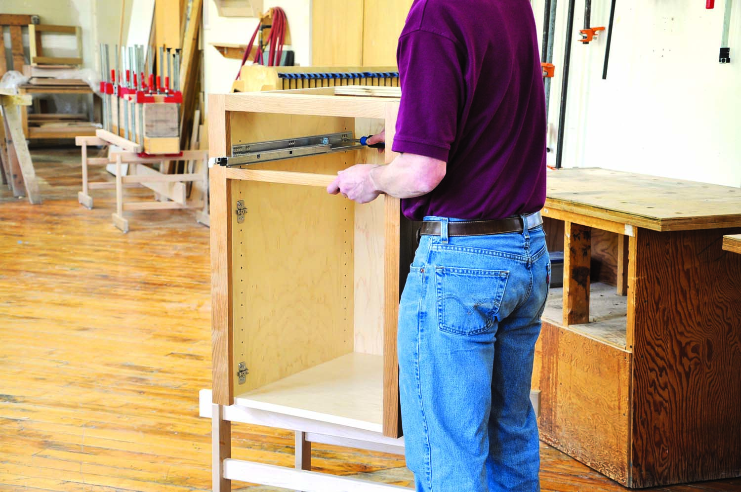
Photo 13. Use the 32mm system holes to mount the drawer and door hardware. Building the inside of the cabinet flush with the face frame significantly simplifies the process.
Unlike side-mount drawer slides, most of the under-mount slide hardware mounts inside the cabinet (Photo 13). To install the drawer, you modify the box and install specially designed clips, so it attaches to the slide. Once the box is installed, you fit the applied front to the opening and then fasten it to the box using washer-head screws. This method allows making minor adjustments after the cabinet is installed, to ensure that the drawer front remains centered in the opening. Sand and finish the drawer box and its applied front after you’ve fitted them to the cabinet.
Wait until the cabinet is installed and the applied front is perfectly centered before you mount the pull. Center the pull, mark the hole locations and then drill through both the drawer front and the box. Size the holes to match the screw shanks, so that installing the screws locks the drawer front’s centered position in the opening. For additional security, I recommend pinning the applied fronts of tall drawers at the bottom, as well, using two screws driven from the underside of the drawer box.
Upper Cabinet Variations
Like the bottom cabinet, the upper cabinet consists of a plywood carcass with solid wood facing (Fig. F). But several variations differentiate it. The face frame has a bottom rail. Both door rails are the same width. The face frame and side panel(s) extend beyond the carcass to create a valence for under-cabinet lighting. And finally, a 1/4″ plywood skin of the same species as the facing covers the bottom of the carcass. This skin is scribed to the wall and attached with construction adhesive and pin nails.
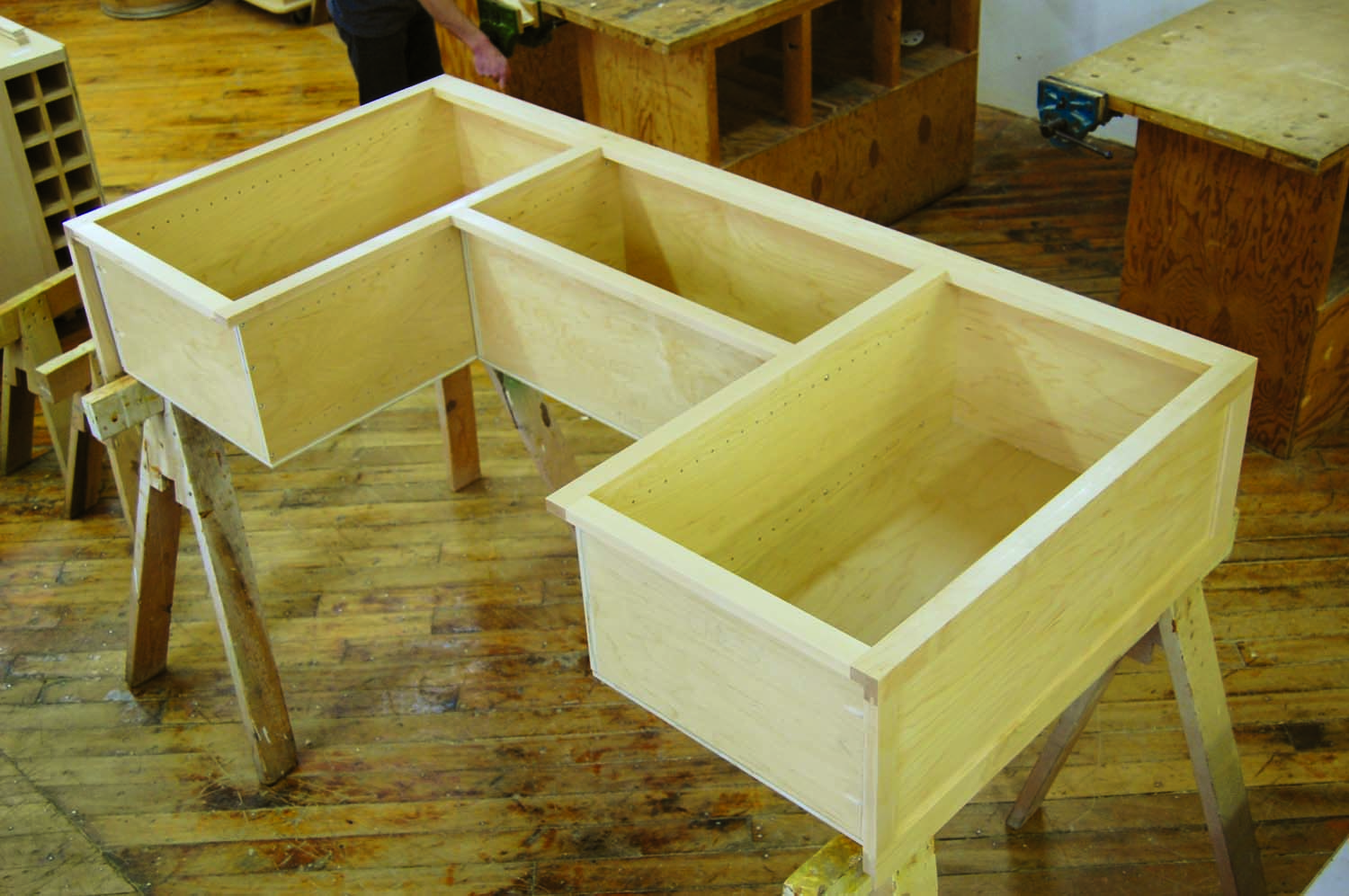
Sidebar: Complex Cabinets Made Easy
One of the many advantages of building your own cabinets is that you can build custom sizes. To make a run of cabinets, build separate carcasses and fasten them together using the 32mm system holes. Drill all the way through matching system holes at the top and bottom of adjacent carcasses and connect them using sleeve nuts and truss head bolts (see Sources). Then glue on a single face frame. Install shims between the carcasses so they’ll mount flush with the face frame’s 1-1/2″ wide internal stiles. Unlike semi-custom cabinets that are individually purchased in a standard size and screwed together, these high-end cabinets show no breaks between the cabinets.
 As shown here, upper cabinet face frames and side panels extend below the carcasses to create valences for under-cabinet lighting. After this cabinet is installed, skins of 1/4″ cherry plywood will cover the bottoms of the maple plywood carcasses. A microwave oven will hide the remaining exposed maple plywood.
Bio
 Greg Larson is the owner/director of the New England School of Architectural Woodworking (NESAW), located in Easthampton, MA. A board member of the Woodwork Career Alliance (WCA) and the New England Architectural Woodworking Institute (NEAWI), Greg has been involved in woodworking for over 25 years.
NESAW offers a nine-month cabinetmaking career-training program, designed to prepare students of all skill levels for immediate employment or self-employment in the cabinetmaking industry. While the program’s primary focus is on the development of safe, repeatable cabinetmaking skills, it also teaches students how to efficiently maximize their time, materials and budget. Students also have the option to learn the basics of cabinet design on AutoCAD and Sketchup. More information is available at www.nesaw.com.
![]() Greg and his wife, Margaret, also run The Workbench, a hobbyist school that offers night, weekend and summer workshops in woodworking, home improvement and gardening. A schedule of all workshops can be found at workbenchschool.com.
Greg and his wife, Margaret, also run The Workbench, a hobbyist school that offers night, weekend and summer workshops in woodworking, home improvement and gardening. A schedule of all workshops can be found at workbenchschool.com.
Here are some supplies and tools we find essential in our everyday work around the shop. We may receive a commission from sales referred by our links; however, we have carefully selected these products for their usefulness and quality.