


We may receive a commission when you use our affiliate links. However, this does not impact our recommendations.
Using a CNC and 3D CAD design to create a carved workbench vise chop.
3D Design and 3D Carving using Digital Tools
I’ve been writing about Digital Woodworking and CNCs for a while now and when it comes to techniques, for the most part, I’ve kept the topics focused on introducing basic processes and concepts that are useful to woodworkers who are new to this world. There’s a lot more digital woodworking basics still to be covered, but that can wait. It’s summer and time for some fun, so I’m going to jump way ahead and take readers for a ride through the world of 3D design and 3D carving in the next several blog posts. It’s my hope that this project will give you some idea of the amazing things a woodworker can create using traditional woodworking skills combined with the latest digital tools.
The Project
Recently, I completed an extensive BARN workbench design project for a local community woodworking group called the Bainbridge Island Artisan Resource Network. In the process, I created 9 workbenches and 11 vise chops. The design approaches and techniques on this project are excellent examples of how to take digital woodworking far beyond the two-dimensional part cutting that I’ve written about in the past. Over the next few posts, I’ll take you through how these vise chops were designed in 3D, programmed with CAM software and finally 3D carved on a CNC. This is a fun project and a great example of the amazing things that can be created with these new tools. So, let’s dive in.

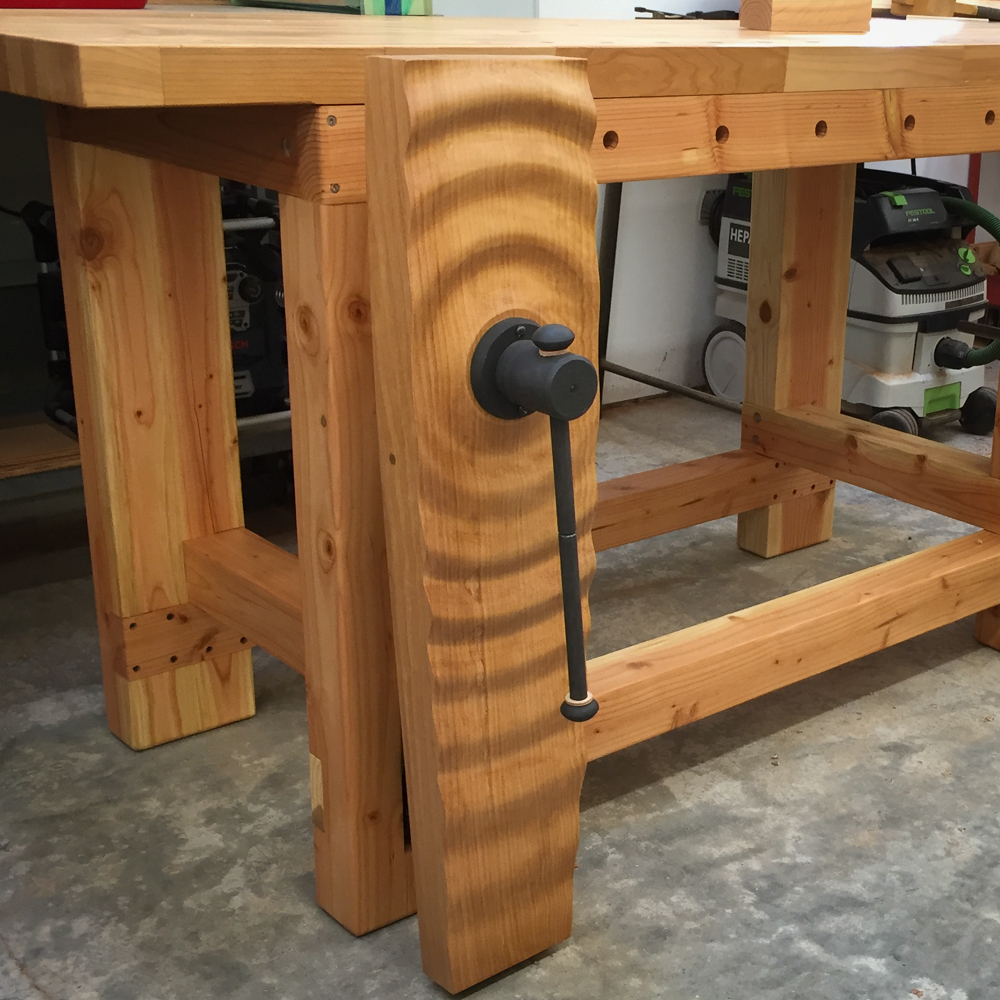
This is where we’re going. A three dimensional vise chop for a woodworking workbench created in a 3D CAD program and carved in 3D on a 3 axis CNC machine. This was vise chop number one. There’s 10 more to show.
A big project needs preparation
If I was going to make just one vise chop, I might have taken a few shortcuts but since I had to make nearly a dozen and with complicated two-sided machining involved, it’s worth the effort to do some extra planning and preparation ahead of time. For this project, we’re not only going to do 3D design and milling, we’re going to do two sided milling — a process is called flip milling. Basically, you machine one side, flip the board over and machine the other side. We have to do this since the chops need to be milled on both sides due to the stock thickness and to machine areas for the vise hardware. To pull it off, you need precise alignment and registration so that the part is in perfect position on both sides of the board. So, for this project, I created a custom registration jig to hold, align and position the parts being cut. More details on that in the next post.
CAD is this project’s primary tool
The CAD software I use is Rhino3D. It’s a powerful but straight forward 3D CAD program that’s easy to learn. For the basic vise chop shape, I just needed a few simple 2D drawing tools that you’d find in any CAD software. For the 3D work that came later, a number of 3D tools and other techniques were used.
I made an early design decision not to use the traditional block with a tail shape of a leg vise chop. I wanted the overall shape to be contemporary because I knew I’d be creating 3D surface patterns. A traditional vise chop shape just wouldn’t fit with the dramatic 3D designs.

Preparation pays off later. Creating center lines for alignment and drawing a box the size of the 36″ x 10″ x 2.75″ wood blanks helps keep your design accurate. I drew a red line along the horizontal X axis and a verticle red line where the vise screw will be mounted.
Create a design platform to work from
Being a project with a lot of variations, I needed to create some standards that I could work from. First, I drew a box the size of my stock material in 2D using simple CAD tools that any CAD program has. The 3D part comes later. The blank stock is sized at 36” x 10” x 2.75” so I drew a 36” x 10” box in Rhino3D. This rectangular shape is also a design boundary that I have to work within and so it keeps me aware of my limits when developing a new curved shape. And, the size of the blanks allow for plenty of extra space for machining and registration pins that are located out of the way of the spindle cutting areas.
Next, since the vise chops are symmetrical along one axis, I added a center line to use as a guide to help during various CAD design operations that I would do later. First, I drew a center line along the long axis — the X axis in my drawings and a center line on the Y axis to locate the vise screw for the Benchcrafted Classic leg vises. Since the position of the vise is critical and everything visually revolves around the center of the vise, it’s important to highlight its location while designing the chop. Finally, I needed to choose an origin point. The location where all dimensions originate from. In this case, I used the top of the blank on the centerline.
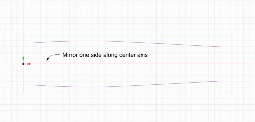
It starts with a simple curve. Once you create the curve, use a mirror command to make a copy flipped the other way. This is a simple way to get two curved lines to symmetrically face each other.
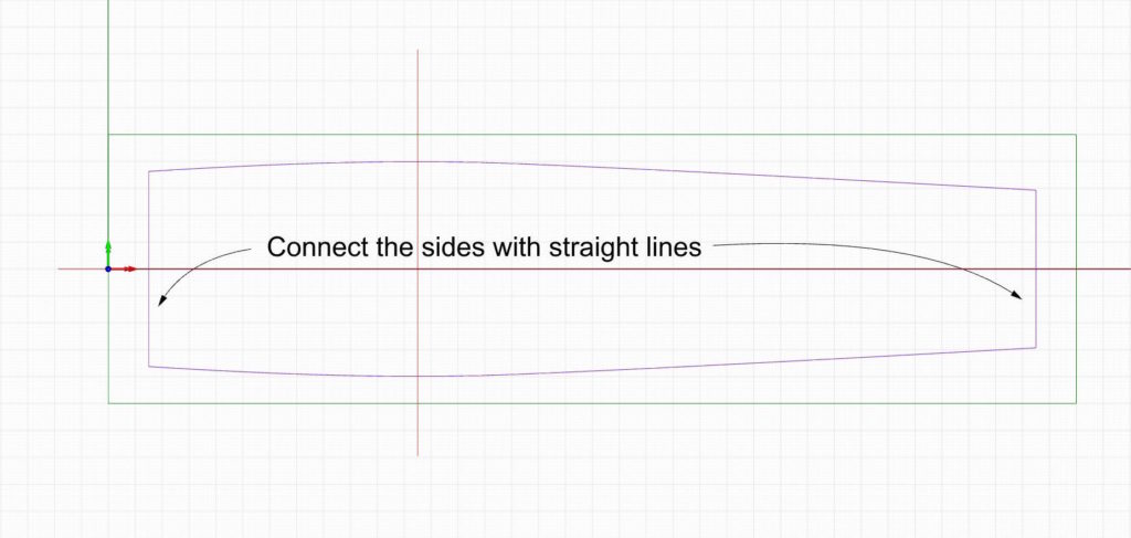
To finish up, just connect the two curves with straight lines and join everything together. This is the basic vise shape for all the designs to follow.
Designing the basic Vise Chop Shape
Now it’s time to draw the shape of the vise chop. Much of the basic design work was done using simple 2D design tools that you’d find in any CAD program. To create the basic shape I used a control point curve drawing tool and drew a smooth curve along just one side. I made the peak outside part of the curve align to the center hole where the vise would be mounted.
Once I was satisfied with the curve shape, I used a mirror command to repeat and flip the curve along the center axis I drew earlier. This way both sides are identical. The final step is to connect the two curves between the two sides with straight lines and join it all together. My basic vise shape is ready to go. One more thing to do before we go 3D. And, that’s to make a jig for alignment and registration so we can mill two sides accurately.
Next post: A dedicated registration and alignment jig.
Additional Resources
- All posts on the BARN workbench click here.
- Photos of the BARN workbench chops click here.
- A video about how the chops were made click here
- Additional Digital Woodworking videos click here.
Here are some supplies and tools we find essential in our everyday work around the shop. We may receive a commission from sales referred by our links; however, we have carefully selected these products for their usefulness and quality.


Pretty damn spiffy Skippy very clever but I find it a bit of a oxymoron to put a CNC chop on a hand tool workbench. Being more of a Hybrid woodworker in the words of Marc Spagnuolo I think the CNC diamond chop it quite tasty. Someday I will convert my Roubo leg vise wheel to the second generation ships wheel as I have wacked my poor old knees repeatedly on that Barney knob first gen wheel.