We may receive a commission when you use our affiliate links. However, this does not impact our recommendations.
Building by eye to recreate a classic.
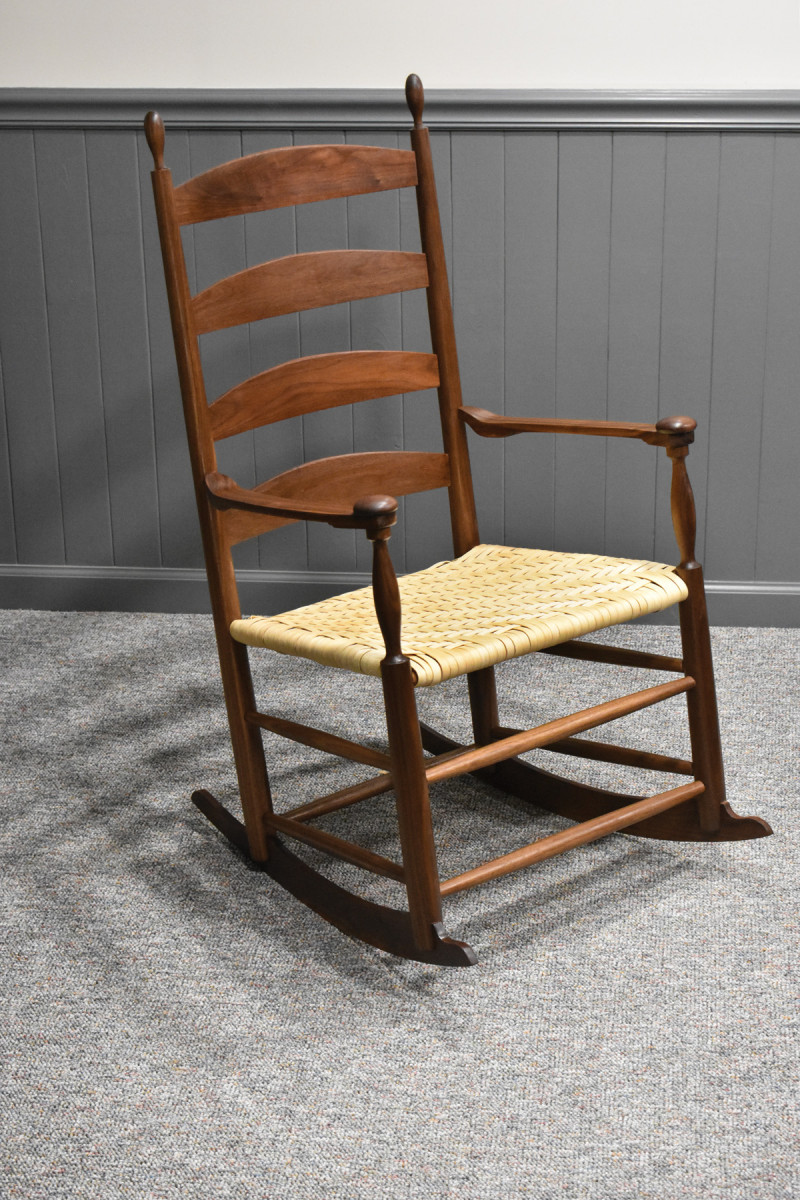
Almost 15 years ago when I was writing Pleasant Hill Shaker Furniture I fell in love with several pieces of furniture originating in that 19th century Shaker community, each of which represented what I saw as a near perfect expression of the Pleasant Hill aesthetic. Among those, in fact standing at the top of that group, is the original of this chair. In the text, I enthused about the coordinated detail evident in this piece, how the cutaway on the bottom of the arms mirrored a similar but more pronounced cutaway on the tops of the rockers below those arms, about the perfection of the curves on the finials and the vases on the front posts.
Unfortunately no one had ever asked me to build this chair—that is until very recently when a friend offered me the commission you see here, detailed in the photos and captions.
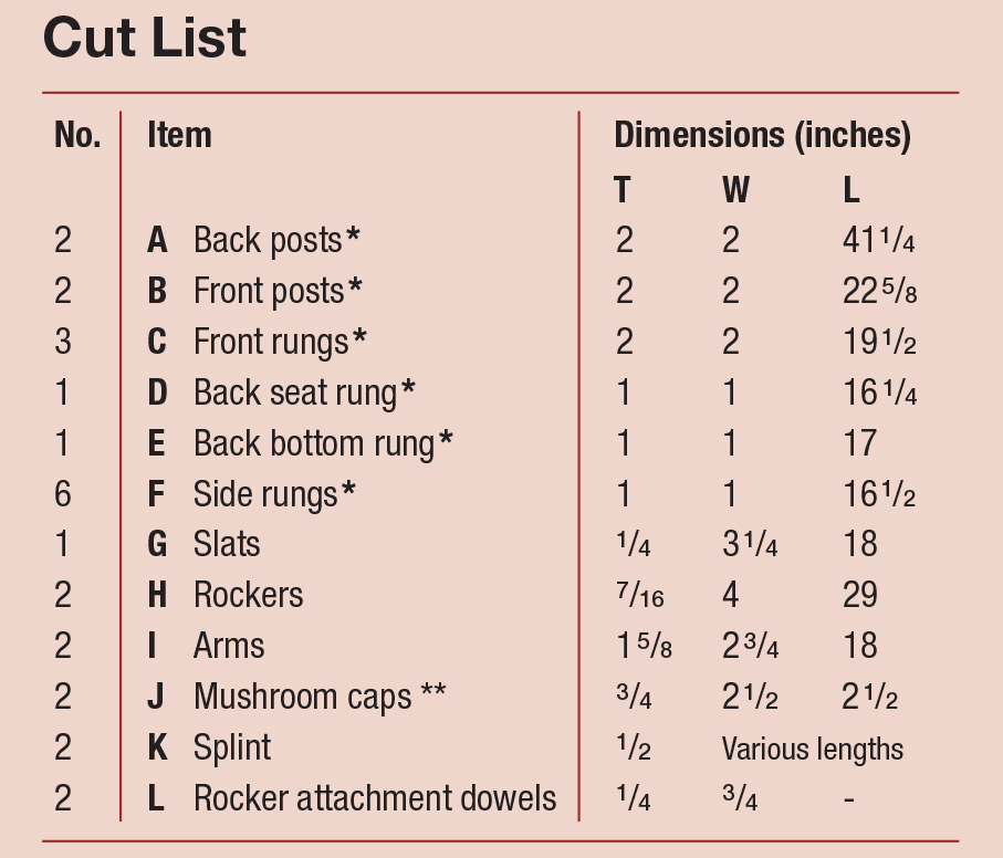
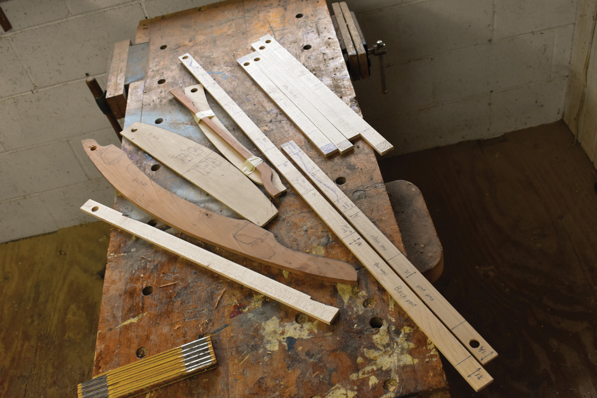
Shaker Rocking Chair Cut List and Diagrams
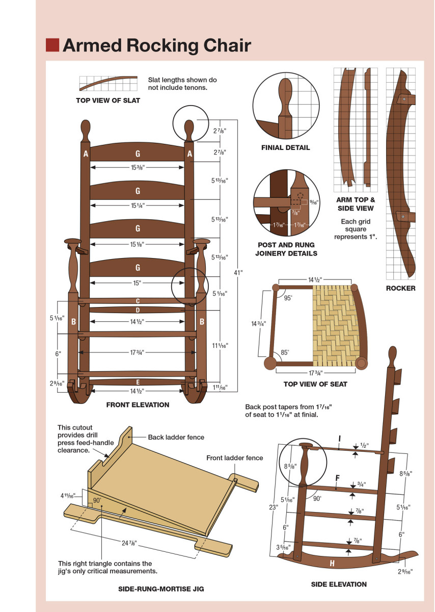
NOTE: These measurements are for the original chair. You may want to increase the size of the chair for today’s humans.
The thickness and width of the turned parts will be reduced during the turning process. This goes for the non-turned parts as well. They will be reduced during the bandsawing process.
* All rungs will end in tenons 5/8” in diameter and 7/8” in length. The show rungs below the seat have slight tapers from 7/8” in the middle to 11/16” at the shoulders adjacent to the tenons. The seat rungs can have greater dimensions. I maintain those greater diameters for most of the length of the seat rungs, tapering them down to 11/16” shoulders over the last 21/2” on both ends.
** The final diameter of the mushroom caps is 21/4.” The extra 1/4” in blank size is leeway in case the blank isn’t quite centered on the caul underneath.
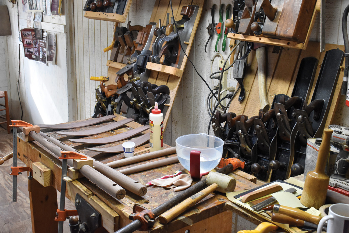
Building by Eye
In 1994 I visited Cleveland-area chairmaker Joe Graham so that I could write a story for Woodwork magazine about the Windsor classes Joe offered in his rural shop. Early on in my visit, Joe mentioned to his students the concept of building by eye. He showed them how to use spotters to align drills, how to rely on their eyes (and their bottoms) to determine when a seat had been fully excavated, how to use only the naked eye to determine the location of a crest rail mortise for a back spindle.
I appreciated Joe’s instruction, but building by eye wasn’t a new concept for me. I had been building by eye since my earliest incursions into the woodshop, driven to it at first because my initial incompetence in the shop meant that I was constantly checking what I did with my eye, looking for the mistakes I was sure I was making.
I didn’t then know how to perform accurate measurements, and I didn’t know then how to transform accurate measurements into effective machine set-ups. What I learned during those years was how to look at a curve to see if there were flat spots, how to decide whether a thing was centered without the use of a rule, how to use my eye when creating the coves and beads and vases of a turned part. Then much later I learned that most of these things could be jigged and fixtured and measured, but by then the damage was done. I had become accustomed to a free-wheeling style of woodworking which did rely on measurements and occasional jigs but which was ultimately dependent on the ability of my eye to see what was right and what was wrong about a part or an assembled piece of furniture.
Early on, this approach sometimes led to disasters, but later it became the most important tool in my evaluation of my work. I learned to sight the front seat rung against a back seat rung to determine the trueness of a chair frame. I learned to establish accurate verticals by eye in laying out a rocker notch in the bottom of a post, to determine if two mushroom caps were close enough in size to appear on the same chair, to evaluate the curve of a slat or a rocker or a chair arm.
Today every bit of work that leaves my shop has been evaluated hundreds of times by a pair of eyes which have become pretty reliable instruments of measure. That doesn’t mean I don’t verify what my eye tells me through the use of a straightedge or a rule. I use these tools whenever I think it necessary, but the overwhelming majority of my checks on the rightness of a part or a finished work are performed with nothing more than the naked eye.
The Plan for this Particular Chair
I went into this project knowing that I was going to change the original design in three ways. First because the customer had chosen walnut, rather the hard maple of the original, I decided to beef up the rungs. I increased the diameter of the mid-point of the rungs from 7/8“ to 11/4“ and made a less dramatic increase in post diameter. Second because contemporary Americans are a good-bit wider than their 19th century predecessors, I added 11/4“ to the width of the chair. And third, I decided to change the way the front posts and the arms intersected. On the original chair the front end of the arm didn’t encircle the tenon atop the front post. Instead, there was a screw driven through the front post and into the end grain of the arm. In my judgment, it’s always a mistake to reinforce post-and-rung chairs with metal fasteners because cracks always appear when the flexing wood of a chair in use is side by side with inflexible steel. So I made up several roughed-in arms to see which would eliminate the necessity of a steel fastener without compromising the look of the arms.
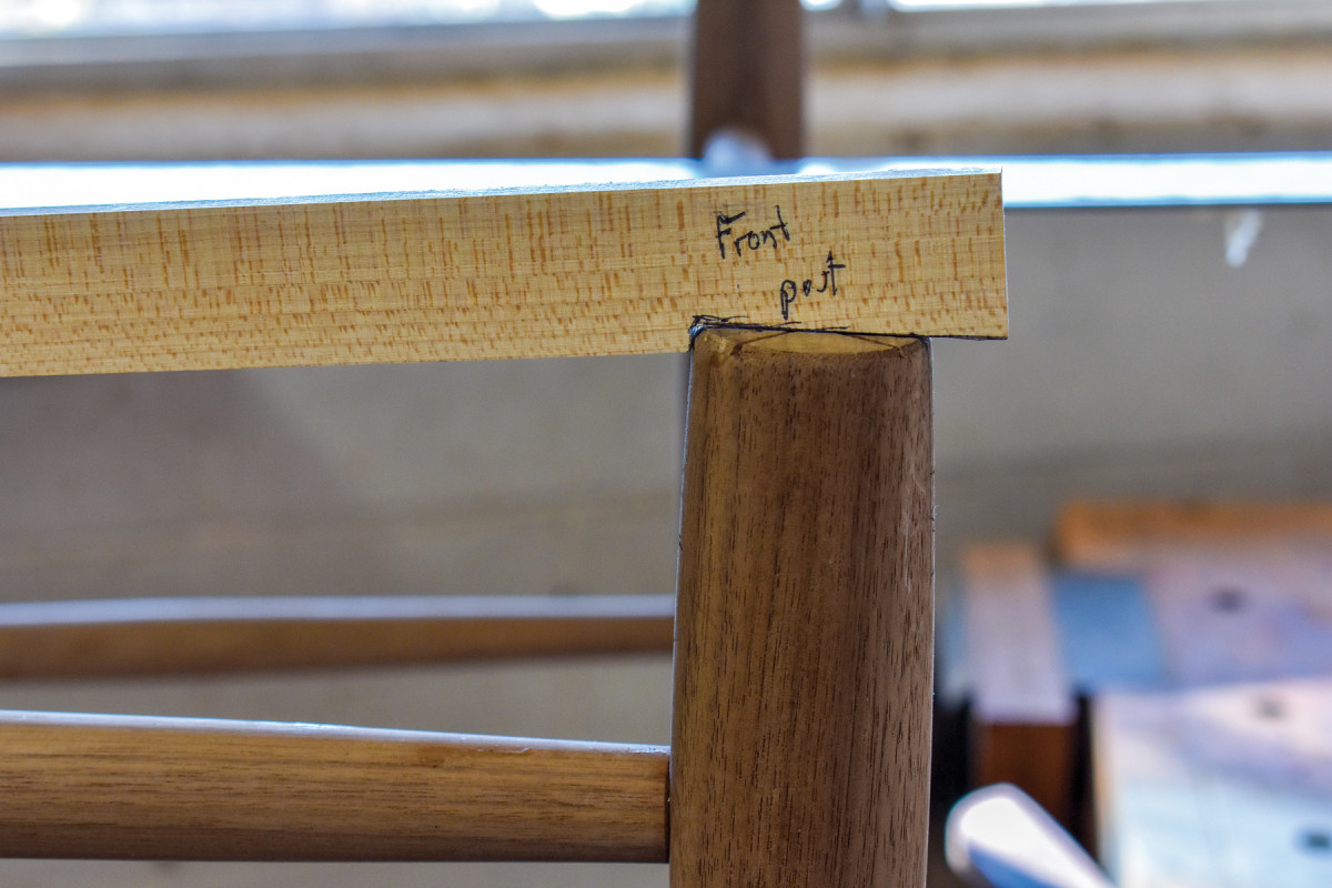
I tried to fit these potential arms, and that’s when I saw it: The arm mortises on the back posts were a full 3/4“ higher than they were supposed to be. My shoulders slumped. I felt a wave of panic. I knew immediately how the mistake had occurred. (See the Managing Catastrophe section further down) This was my first reproduction of this form, so the story sticks were fresh-hatched and untested and—at least in the placement of the arm mortises—totally wrong.
Then, after the panic, I settled in and became a woodworker.
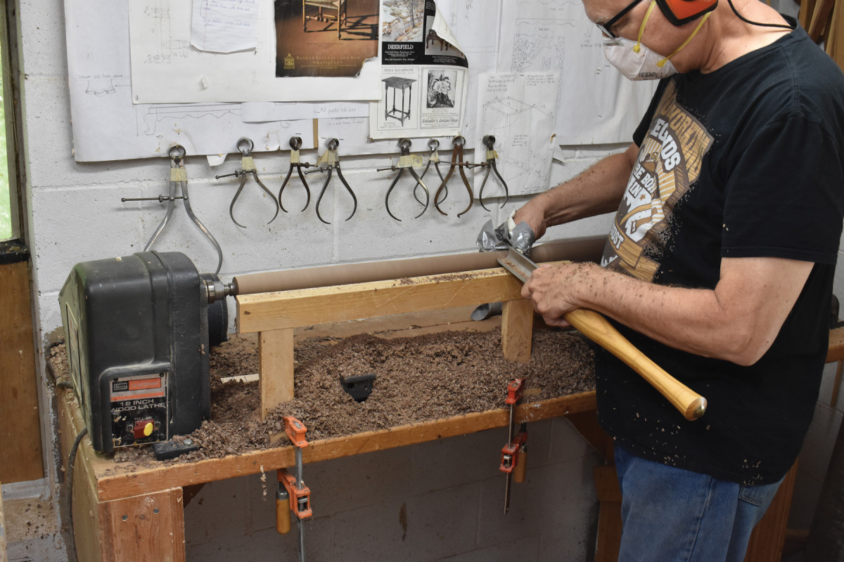
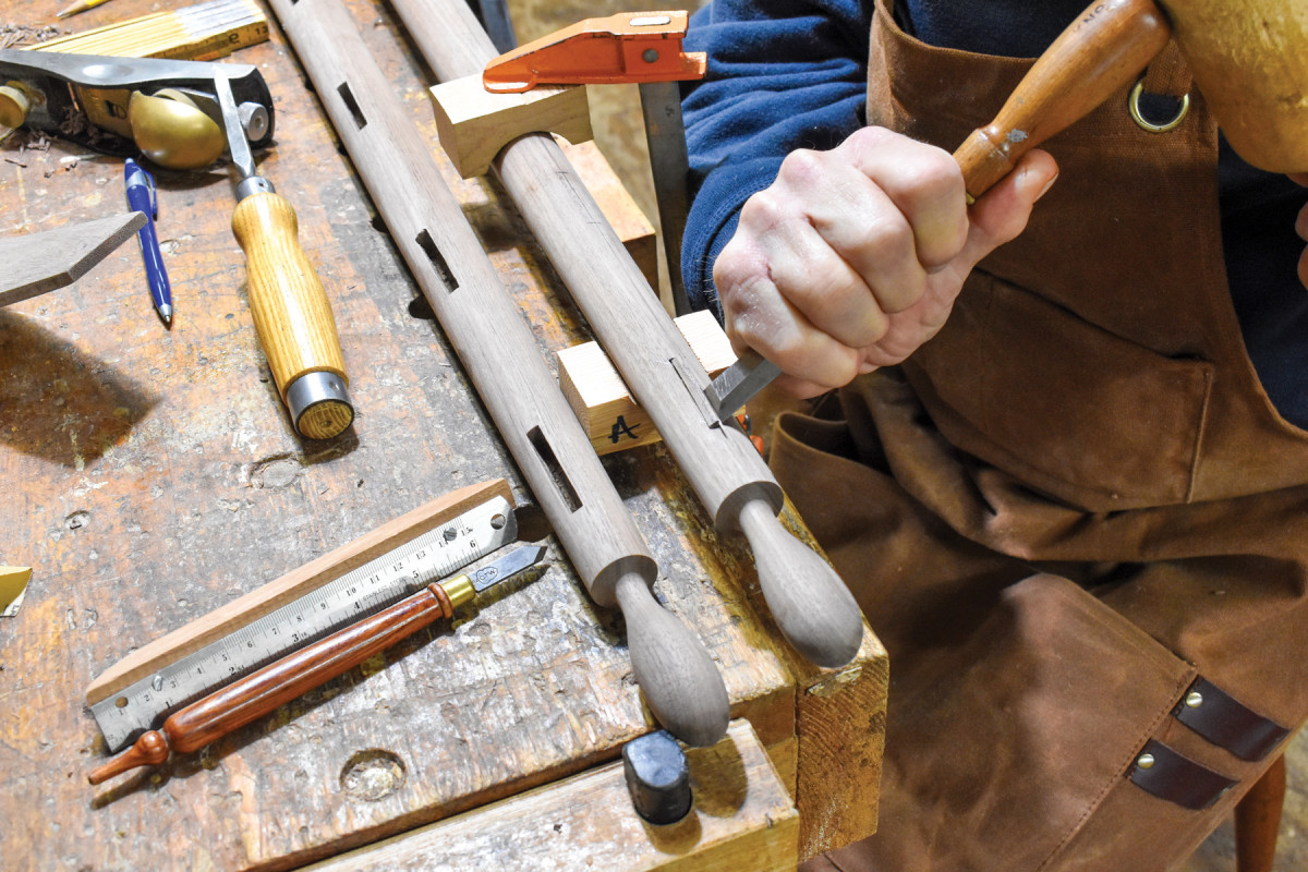
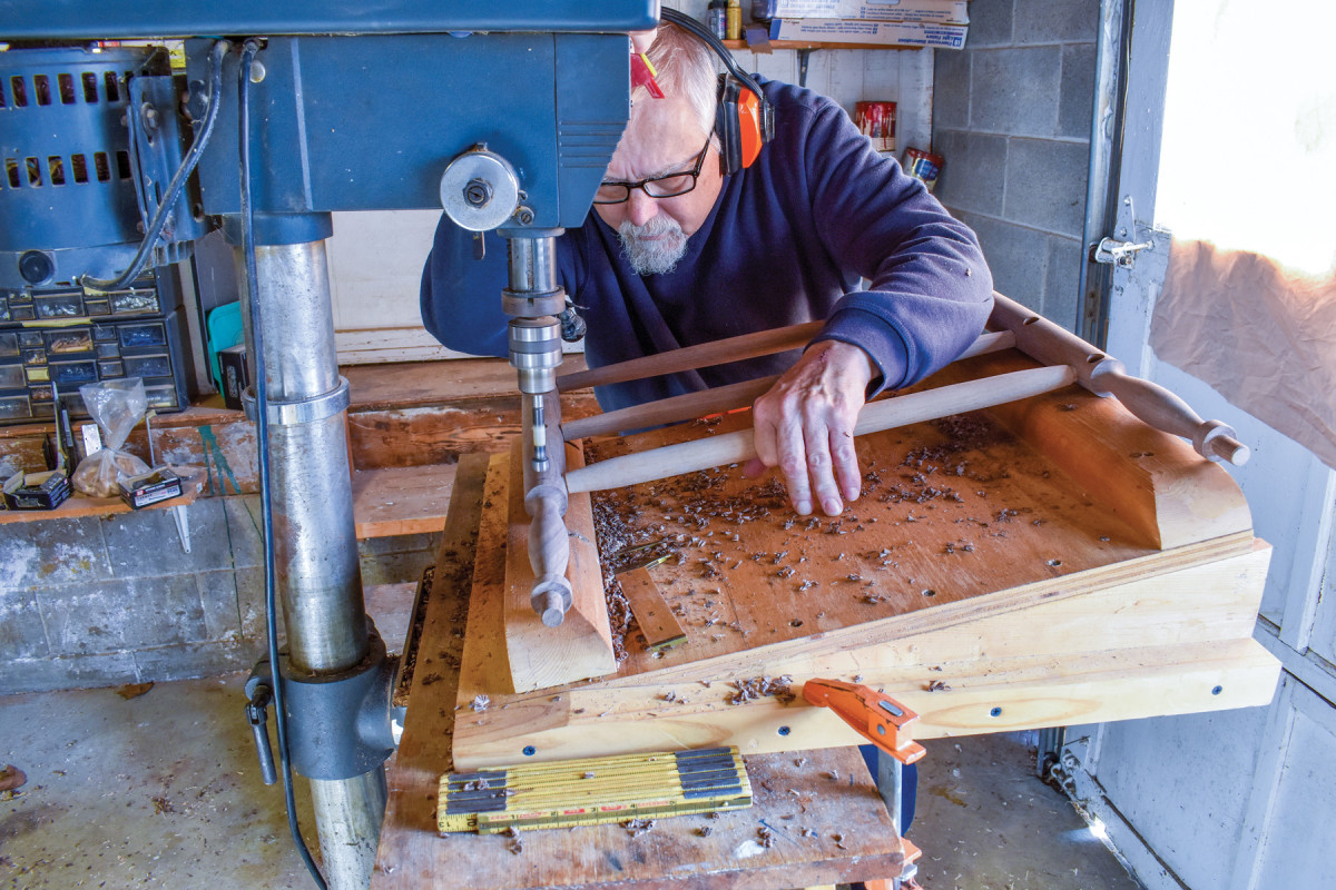
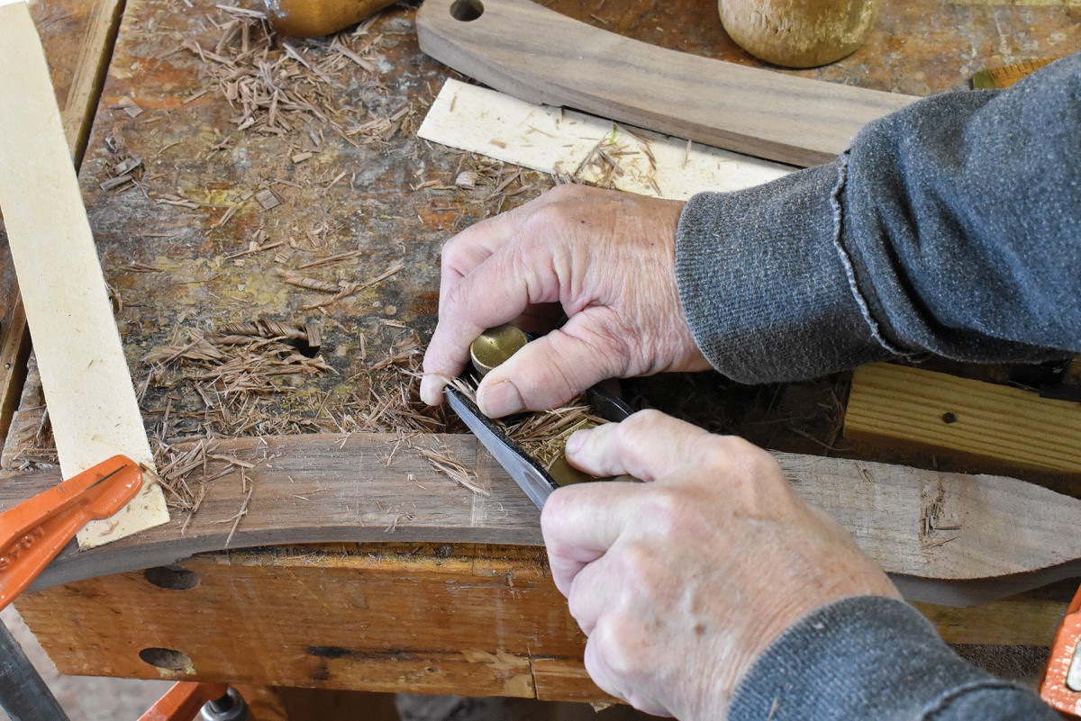
1. I use the palm of my off hand as a steady rest to reduce chatter when turning the posts. To protect that off hand from friction burns, I slip that hand into this “Ugly Ball of Tape” I’ve wrapped around my hand over the last 30 years.
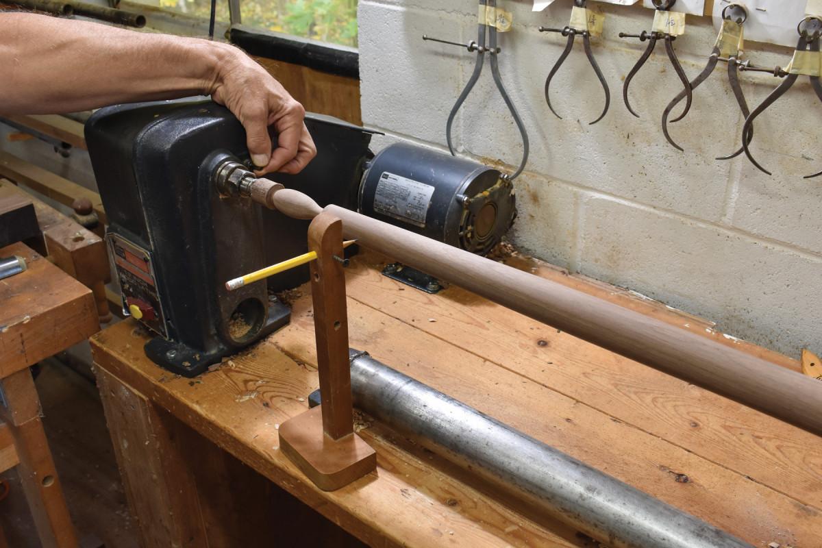
2. Once the entire length of the back post has been tapered, I use my story stick to transfer locations for turned features.
3. I use a 1/4″ fingernail gouge and a 1/2″ skew to create the turned features. (See “Scalloped Edge Table” in the August 2018 issue of Popular Woodworking for a further discussion of my turning methods.)
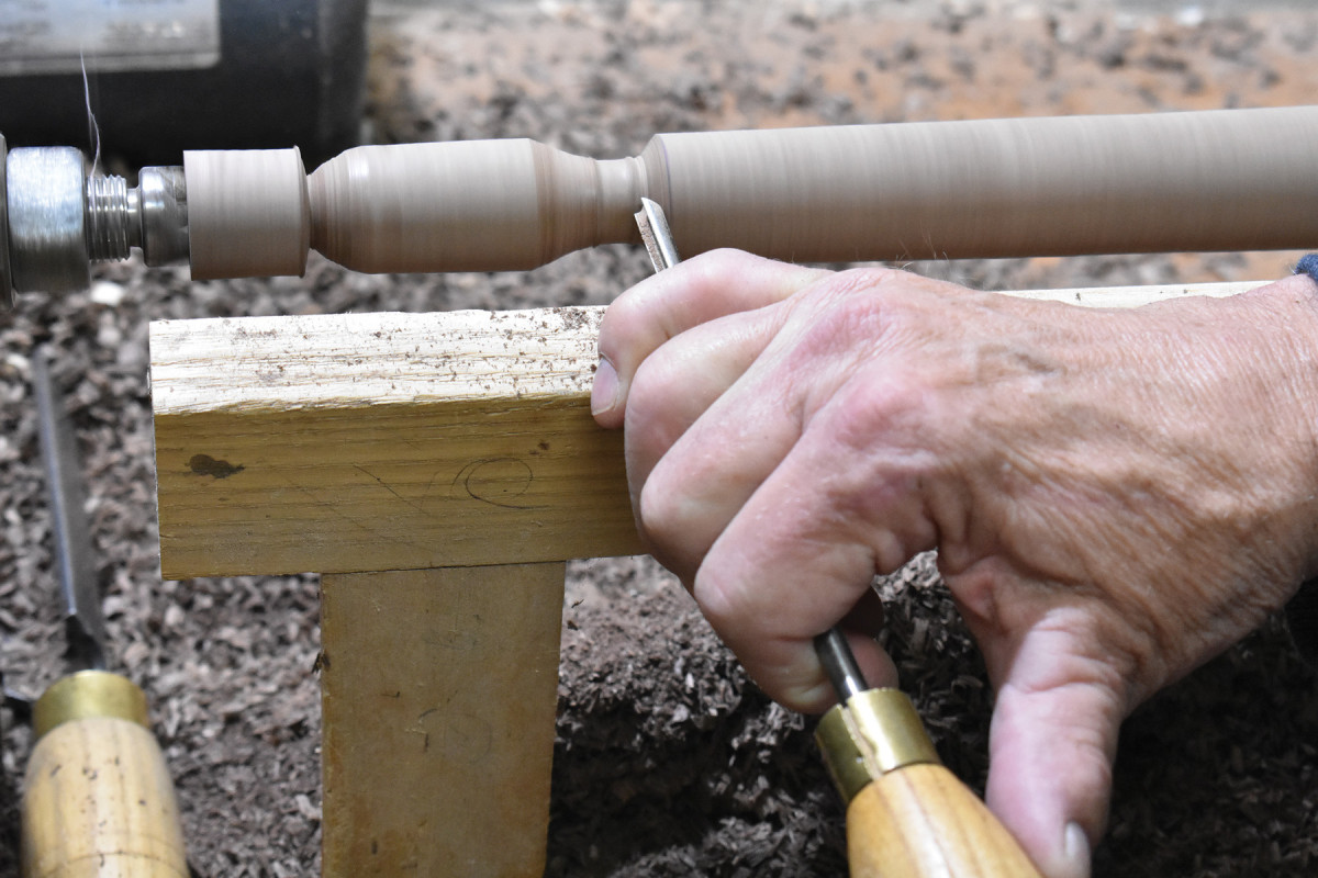
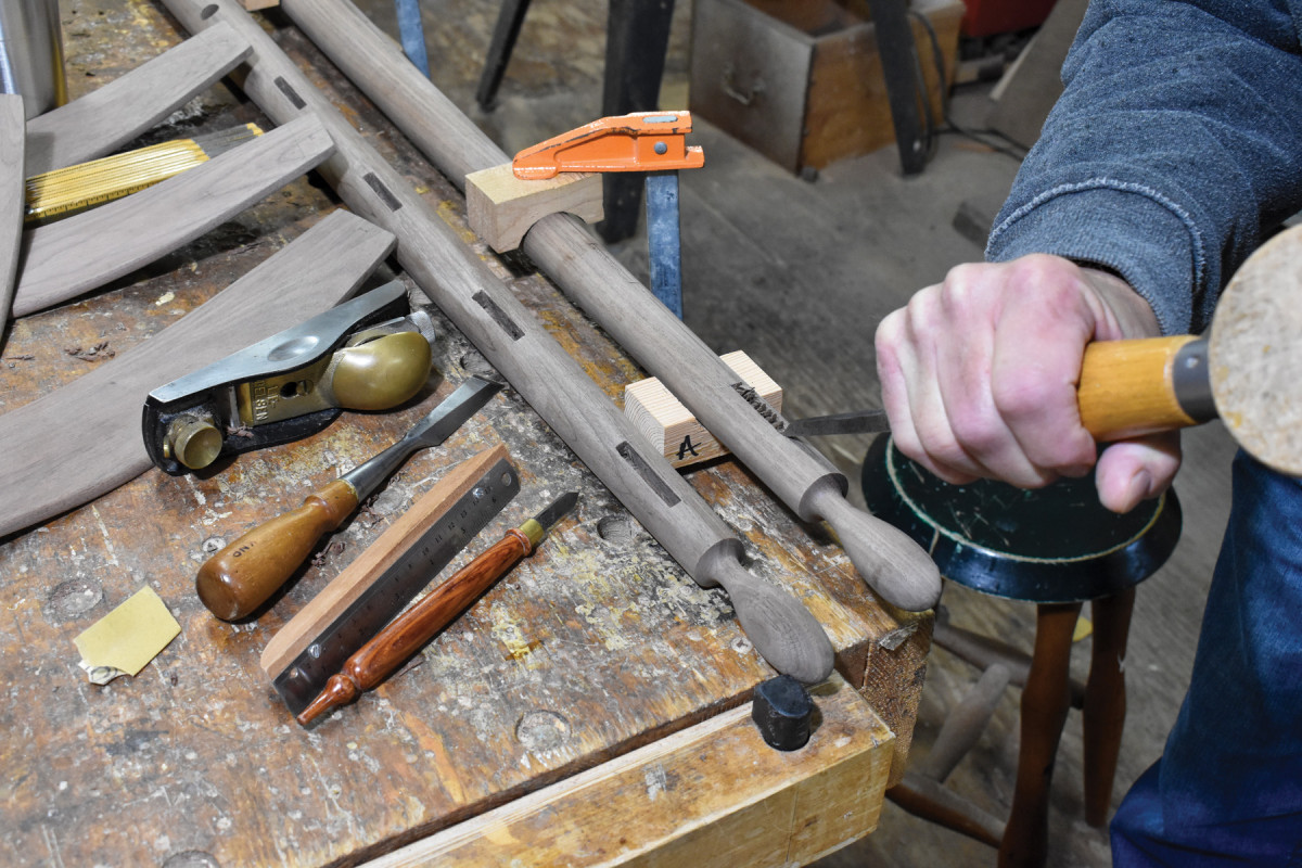
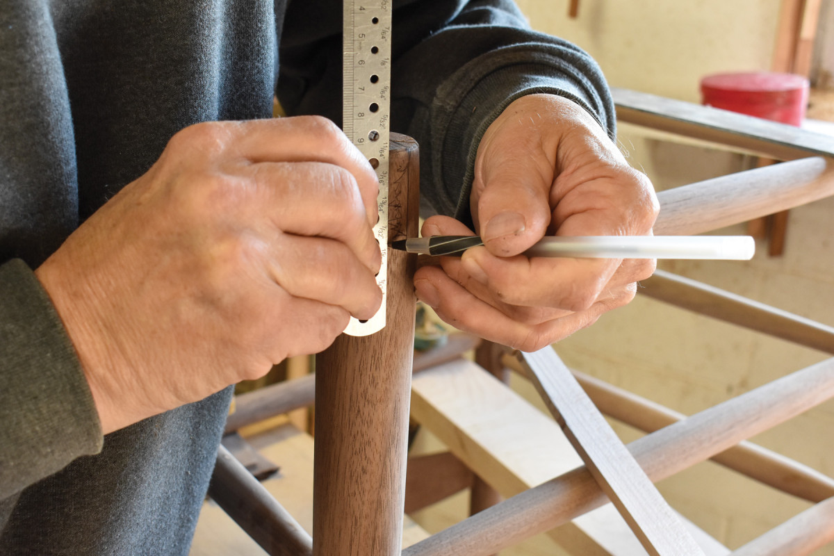
4. My lathe has an indexing head centered on the lathe’s axis of rotation with 36 stops, each one 10° from the next. This means that if I want to create lines 90° apart, I can locate them by counting off nine stops on the indexing head using the spring-loaded pin you see here between my thumb and forefinger. However this particular chair has side rungs 85° from the front rungs and 95° from the back rungs. This means that counting off either 9 or 10 stops on the indexing head will provide me with lines equally close to the chair’s ideal. I chose 9 stops for my line placement. (The side rung mortise jig—SRMJ—will create the actual placement of the mortises around the posts’ circumferences.)
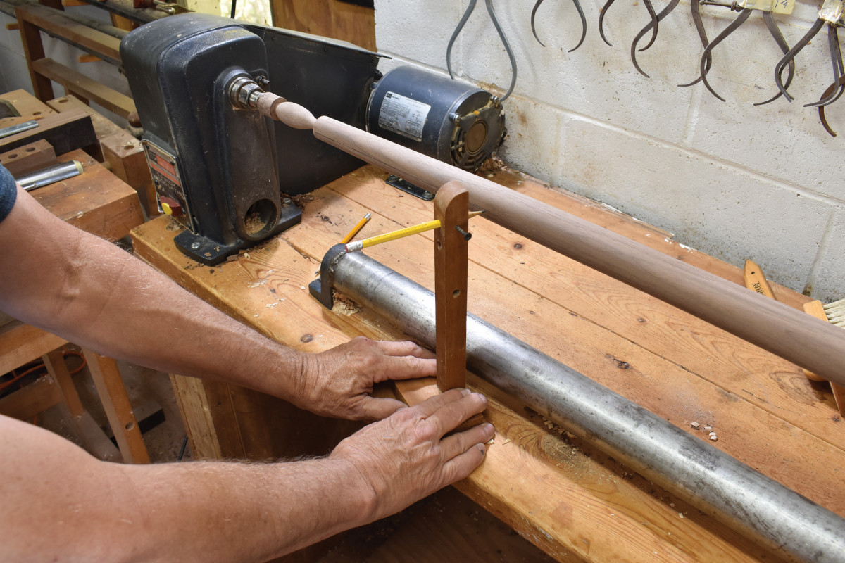
5. To draw the lines along the lengths of the posts’ outside diameters, I use this simple jig which does nothing more than hold a pencil point at a height equal to the distance between the bench top and the lathe’s axis of rotation.
6. To mark mortise locations along these lines, I lay a story stick along a line and transfer the info to the post. (Remember that every chair has a right and left front post and a right and left back post. Make periodic checks to ensure that you don’t end up with two rights or two lefts. Posts drilled that way can’t be made into a usable chair.)
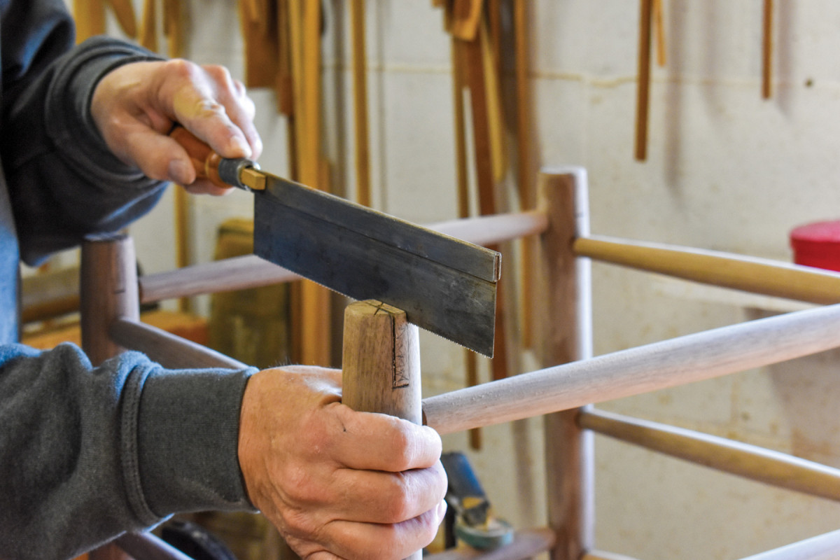
7. Using an eyeball measurement, I rotate the front post until the line representing the front-rung mortises is facing directly up. That rotational position is locked in place by turning two screws through the jig’s 1/4″-thick end piece into the bottom of the post.
8. With the front post’s rotation locked in, I bring the Forstner bit down into the work. With straight-sided posts, it’s possible to work to a fence, but with tapered posts like these, you have to eyeball each one.
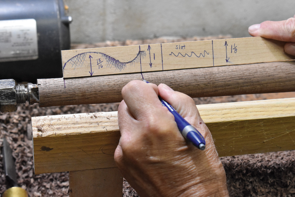
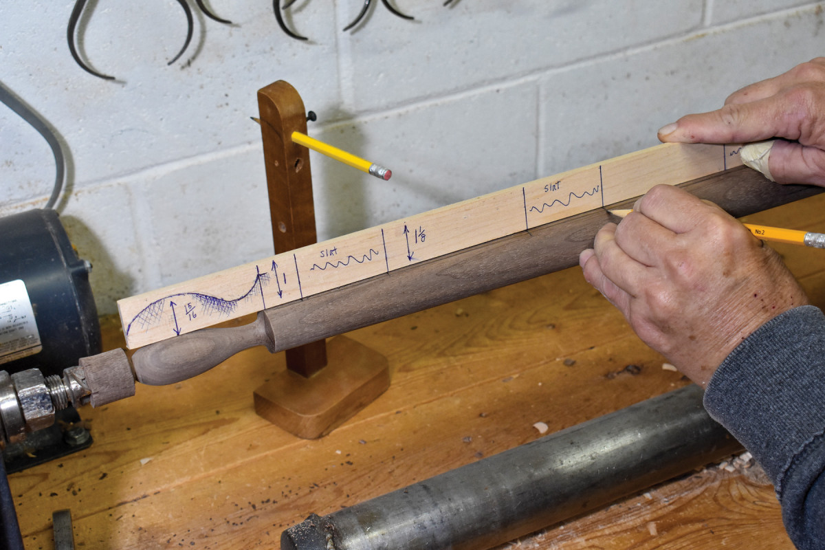
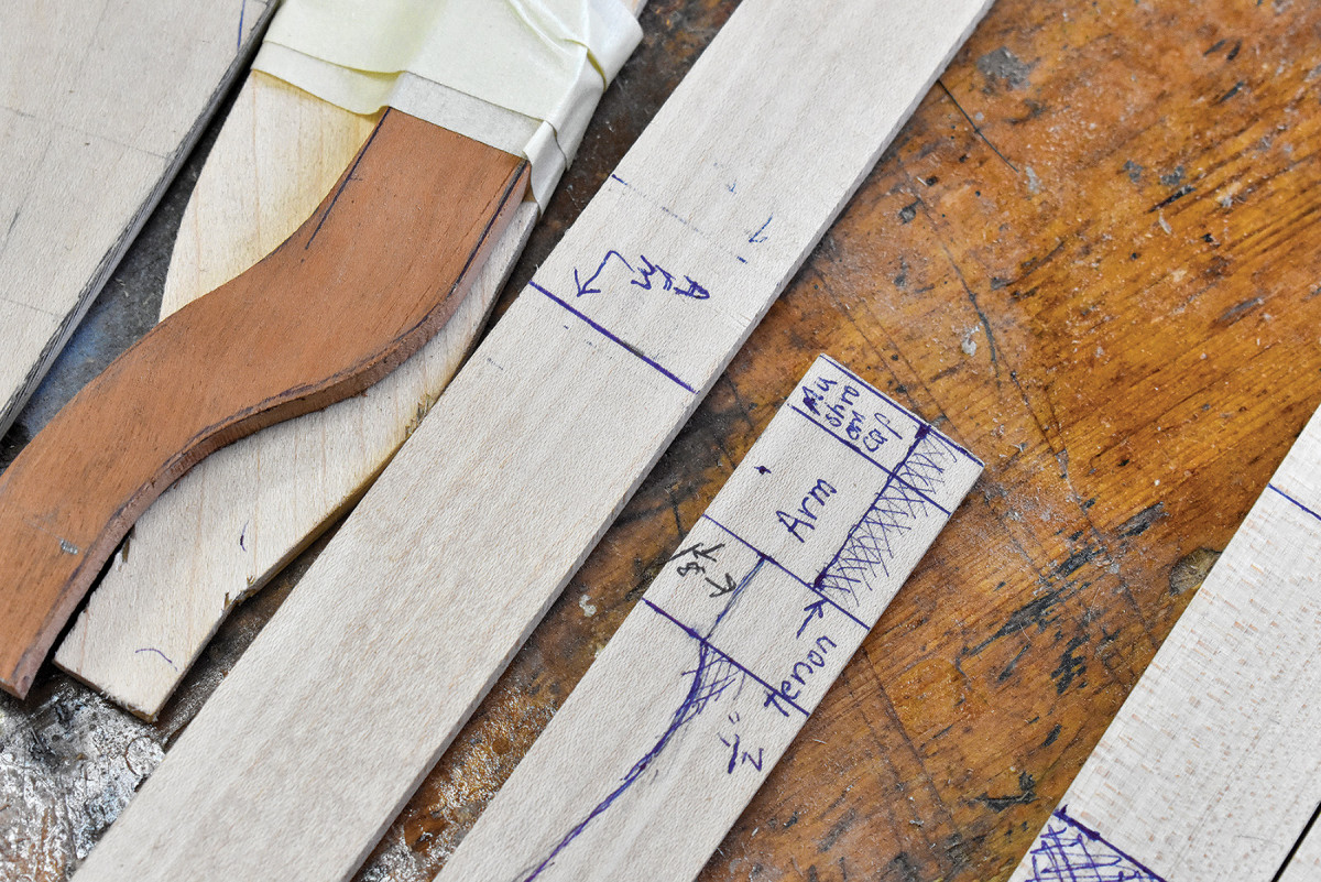
9. In this close-up of the slat pattern, you can see that on the left I have the measurements of the blanks from which slats can be cut. In the middle of the image, you’ll see that I’ve sketched in four half slats numbered one through four with #1 representing the top slat and #4 representing the bottom slat. Included in each sketch is the measurement indicating how much of the slat needs to penetrate the post, as well as the length of each half slat.
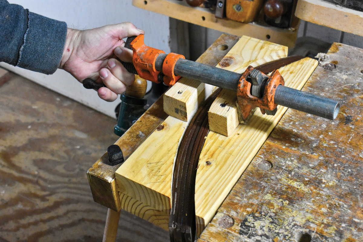
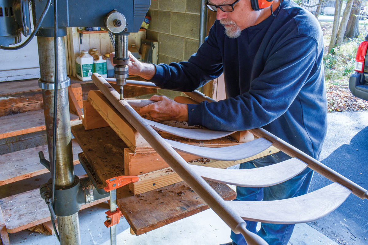
10. Unlike most of the chairs which leave my shop, the back posts on this example are not bent which means I had to steam only my slats. (You can also boil the slats in a pan for 30 minutes to plasticize the wood.) After a half hour in the steamer, I arranged them in this set of molds, creating the bends by closing the vise and using a pipe clamp to ensure that the top of the stack stays tight. *Making bending forms (molds): In the top left of the drawing on page 41, there is a sketch of the amount of bend in the finished slat. When you’re making your forms, please remember that there will be a certain amount of springback when the slats are released from the forms. This means the bend should be slightly exaggerated in your forms.
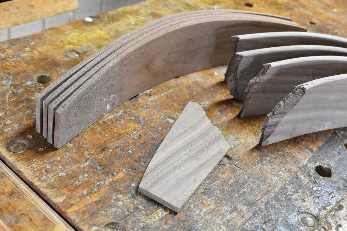
11. The first set of slats I made for this chair came out of the forms as shown here. The culprit? I suspect the drying practices of the mill that prepared the material. I’ve had problems with honeycombing in material from that supplier. My solution was to make the next set of slats from material I knew to be air-dried. Those slats came out fine.
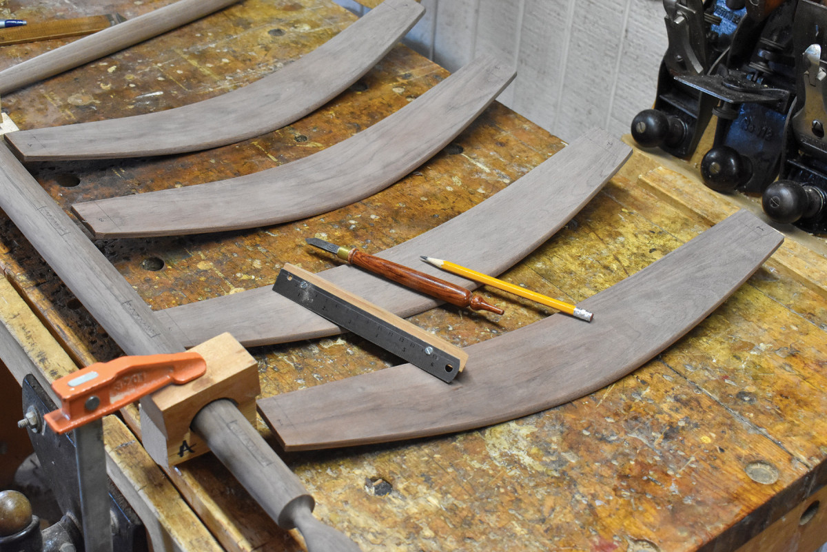
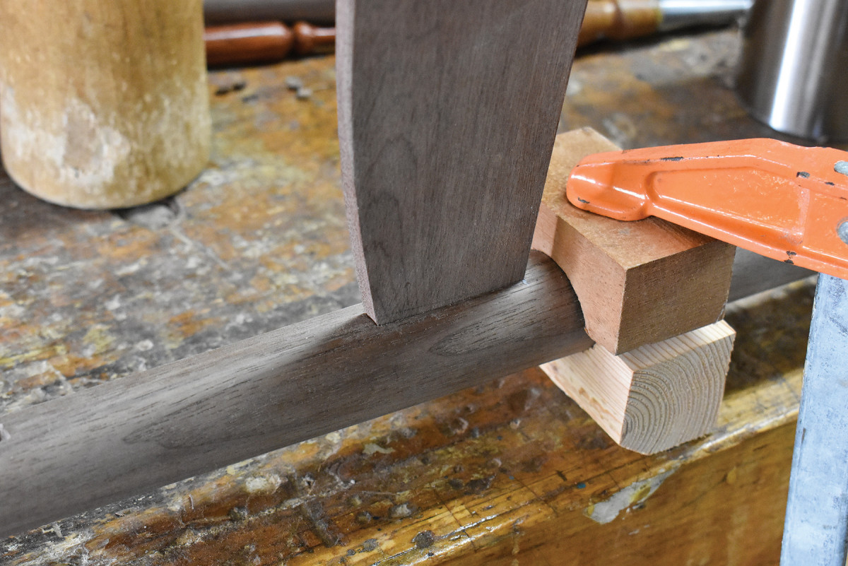
12. Careful preparation eases the way to successful construction. In this photo, you can see the post clamped to the edge of my bench through the use of U-blocks. Also note that the slats are laid out in the order each will occupy in the finished back ladder. Notice too that the depth of penetration is marked on each slat. The overall length of the slat and the depth of penetration varies from slat to slat, the higher the slat is on the post, the less the penetration. The penetration depth for each of the four slats is written on the slat pattern.
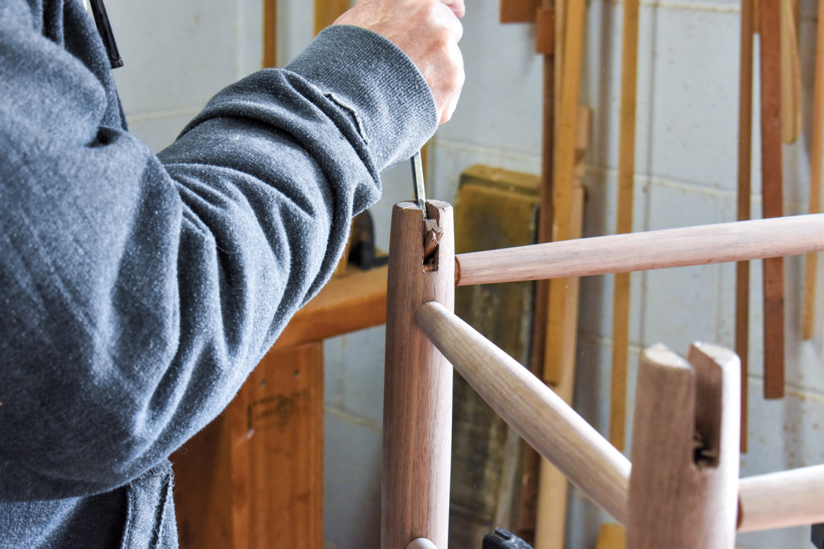
13. My first step is to lift the long top chip from the mortise location.
14. I then begin to nibble away at the waste within the mortise using a 1/4″ mortise chisel, ground to a width of about 3/16″. (It’s impossible to do meaningful work in a 1/4″ mortise with a 1/4″ chisel.)
15. Rung mortises are drilled on the lines I marked in Photo 2. Slat mortises are chopped with that line forming the front edge of the mortise. They are chopped at an angle in comparison to the rung mortises. Notice that the slat in this photo sits in a mortise angled so that slat will enter the (not pictured) second post at the same angle as it enters the post shown in the photo.
16. A good slat mortise should have no gaps around slat.
17. To avoid disaster and stress, I always take time to lay out the tools and materials I’ll need for glue-up. (Back ladders are notoriously difficult to assemble because there are so many tenons and mortises to glue and align.)
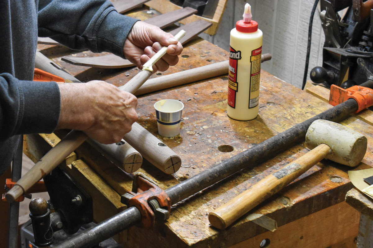
18. Glue is cheap and strong, so make sure that each tenon and mortise is glued before assembling. This means that squeeze-out has to be washed off the finished assembly.
19. The tips of slats and rungs can both get hung up on the walls of mortises. In the case of the rungs, all you can do is continue to apply pressure with pipe clamps, but sometimes this doesn’t work for the slats. To encourage slats to unstick, you can lay the ladder on a bench and press down on the slat bend causing it to flex and release with a pop.
20. The side rung mortise jig (SRMJ, see illustration on page 41), a wedge of assembled wood resting on a wood deck, creates the angle between the back and side rungs, as well as the angle between front and side rungs. In this position, it creates the angles between the back and side rungs. There are no fences on this jig. I simply eyeball the Forstner bit into the proper locations on the back posts. To drill the mortises in one back post, the ladder is placed in this position. To drill the mortises in the second post, the ladder is rotated 180° so the undrilled post sits beneath the Forstner bit.
21. To drill the side rung mortises in the front ladder, I rotate the SRMJ 180° and drill. 21 To drill the side rung mortises in the front ladder, I rotate the SRMJ 180° and drill. *About the SRMJ: The angles between the side and back rungs and the angles between the side rungs and the front rungs are supplemental. This term identifies any two angles which total 180°. The SRMJ is made of a pair of 2 x 6s cut to size. I attached a plywood deck wide enough to accommodate a front ladder. To the assembled wood wedge, I attached a pair of clamping strips so that the SRMJ could be attached to the wood deck of my drill press. That construction is enough to drill the side-rung mortises in the front ladder, but the back ladder requires two more parts. Because of the curve in the slats, the posts of a back ladder need to be raised above the deck. For that purpose, I cut a pair of 2 x 4s and fastened it to the angled deck of the SRMJ with just two screws apiece so they can be quickly moved to new positions to accommodate ladders of different widths.
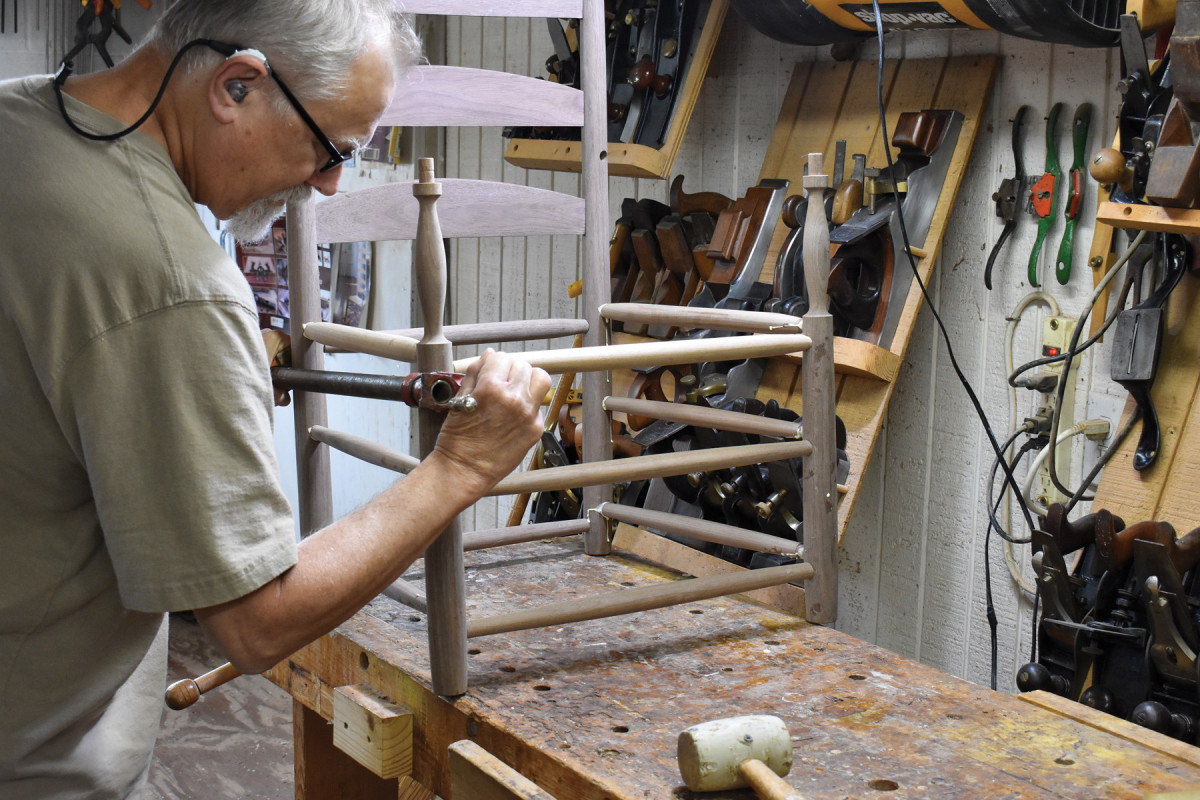
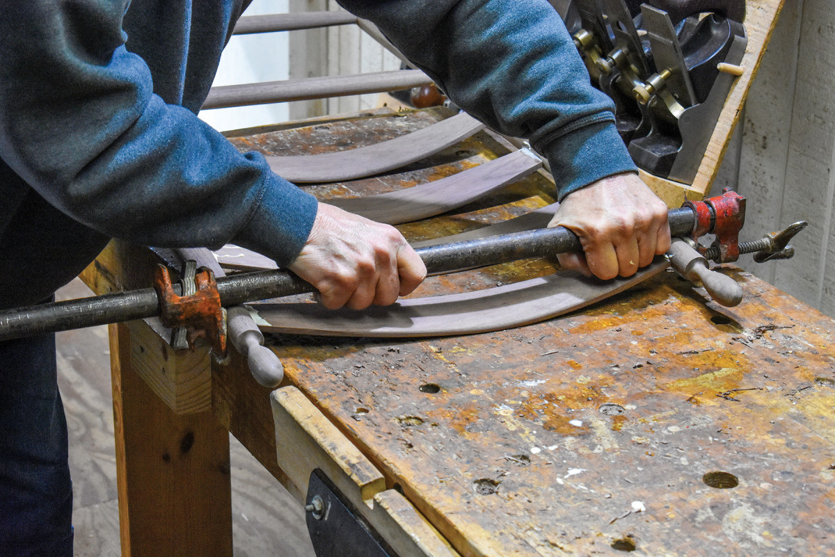
22. Once the tenons have been glued, I push them deep into their mortises with pressure from my pipe clamp.
23. As you can see here, a straightedge won’t lay flat on the end of a post when that straightedge is laid across the bottoms of the two posts on one side of the chair. This makes marking the bottom of the post very difficult.
24. However, this can corrected by laying a slat of wood across the bottoms of the posts on one side of the chair after cutting bird’s-mouths in the bottom edge of the slat.
25. The rockers on this chair are 7/16″ thick. I, therefore, mark out 3/8” thick notches. (The extra 1/16″ of width will be pared out while fitting the rockers into the notches.)
26. I then saw the two sides of each notch.
27. To remove the waste, I drill through the post within the limits of the notch with a 5/16″ bit.
28. I then break out the waste with a chisel.
29. With a paring chisel, I fit each notch to the rocker.
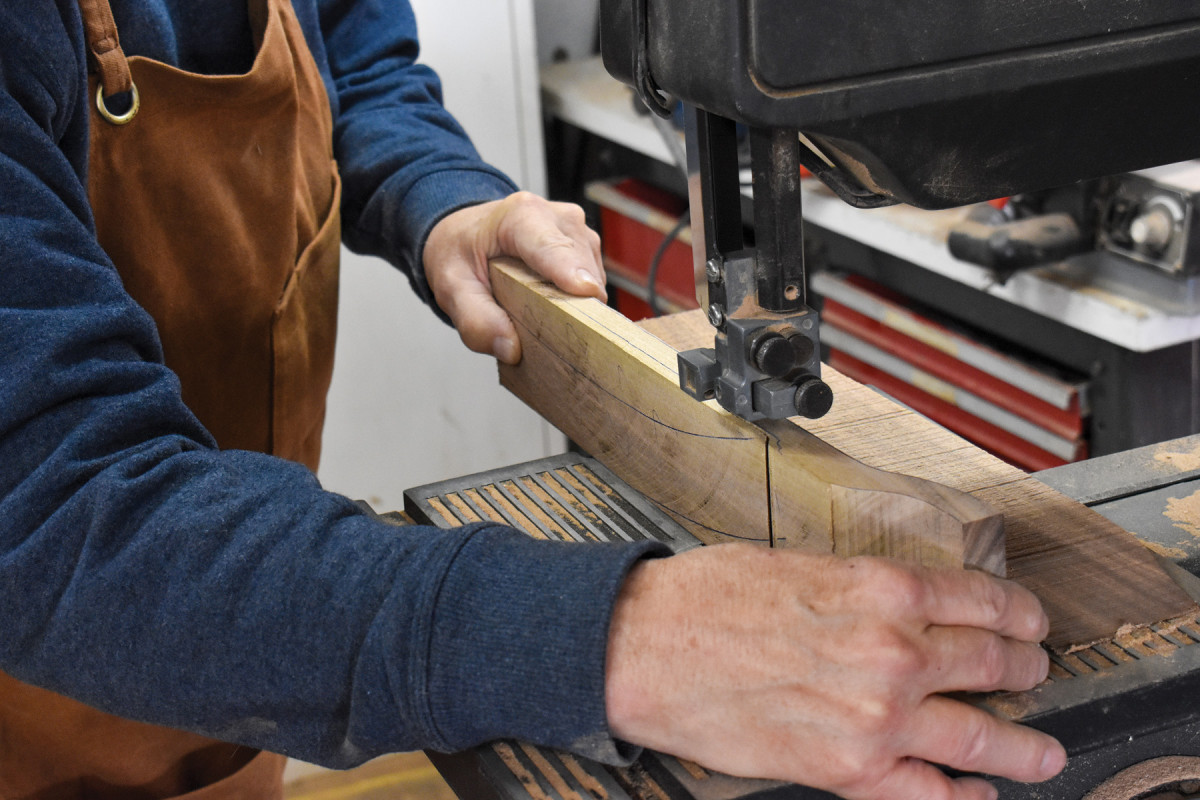
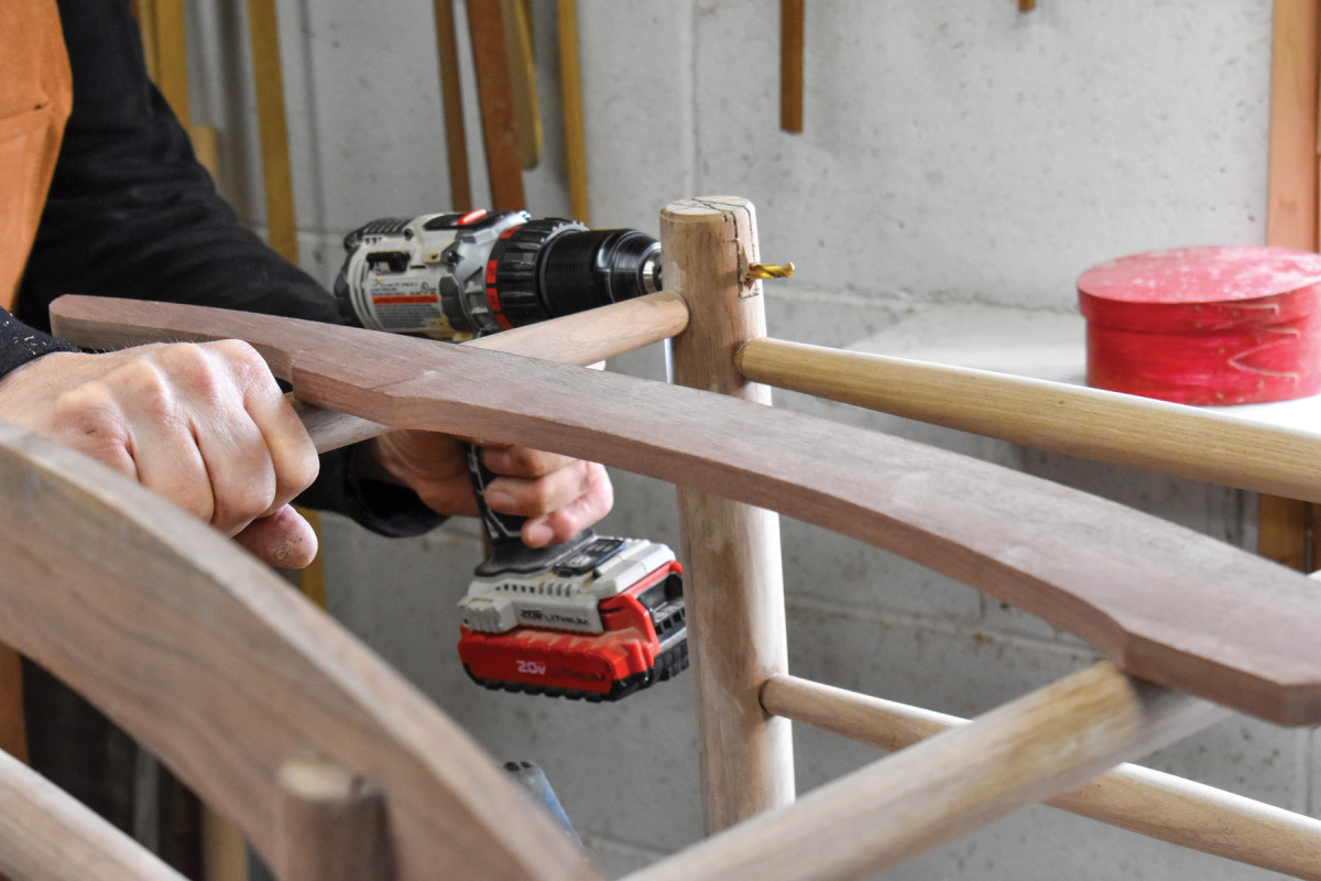
30. The arms must be cut in two adjacent planes. In this photo, I’m cutting the top and bottom planes.
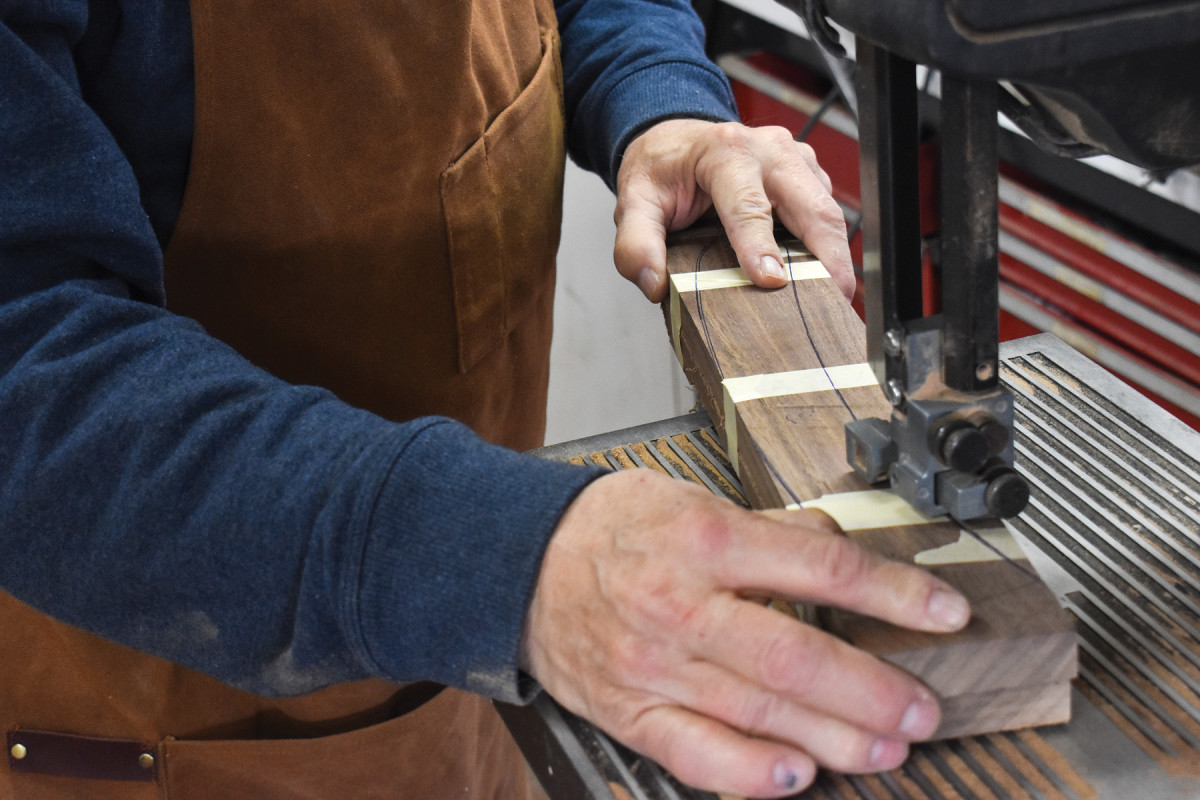
31. After reassembling the arm blank with masking tape, I begin to make cuts that will define the two edges of this arm.
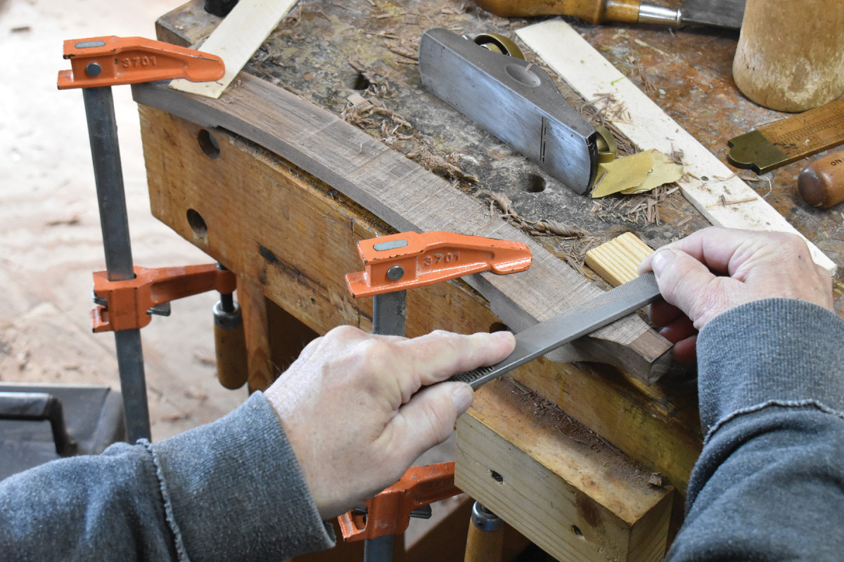
32-33. A block plane can be used across the grain as well as with the grain. Here, I’m planing the bottom middle section of the arm.
Other sections require the use of a rasp.
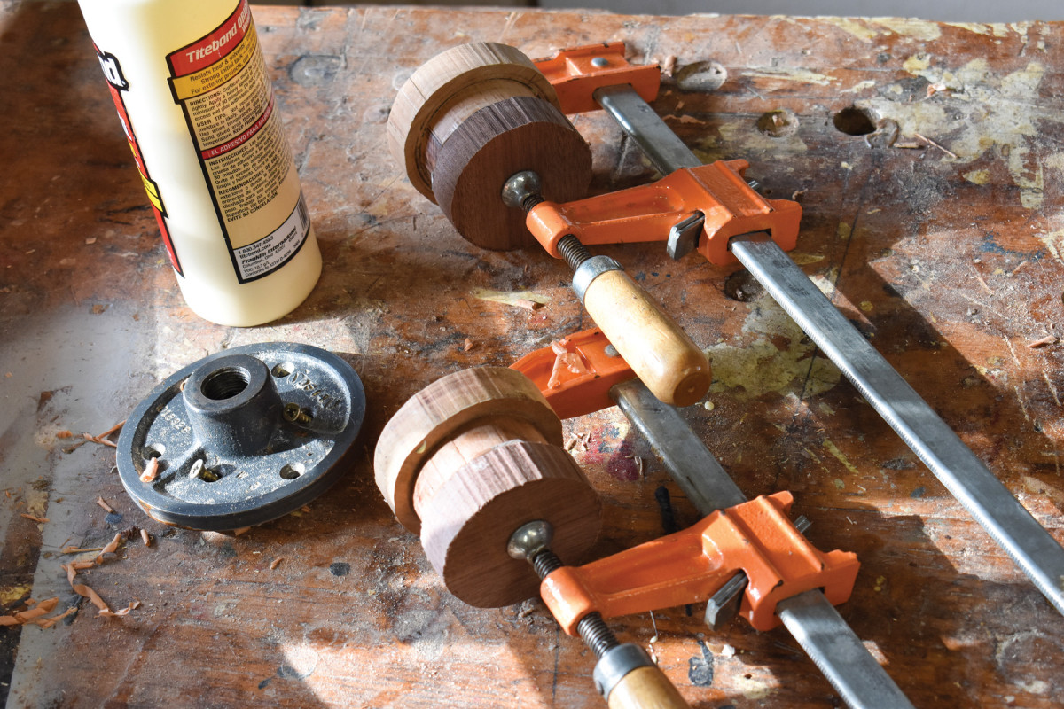
34. The mushroom caps atop the front posts have a contour that reaches all the way to their undersides. That means a two-part turning caul is necessary. The first, the larger caul is drilled to receive the screws that attach the face plate. The second, the smaller caul, is glued to the first and is then glued to the mushroom-cap blank. In both cases, the glue joints are constructed with a bit of newspaper between the wood components. I clamp them as shown, then leave them overnight.
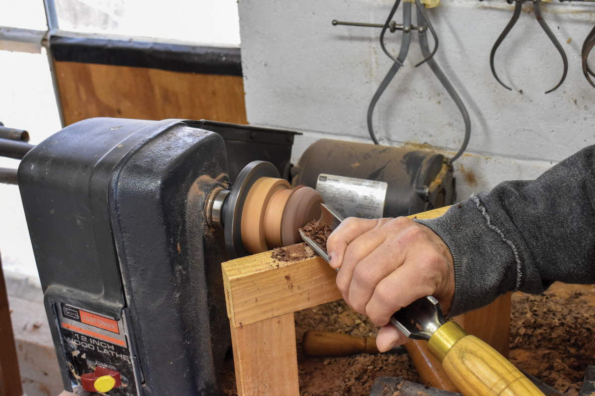
35. I don’t have any gimmicks or special tools for face-plate turning. I just work from the center out with a roughing gouge, then work the radius with a 1/2” skew.
Managing Catastrophe
During a half century in the shop, I’ve taught myself to use steam to inflate bumps on furniture parts, that even deep gashes in the wood can be removed with some clever work with a hand plane or a rasp and sandpaper, how to lengthen mitered parts with a hand plane (yes, it can be done), to use clamps to seat a set of dovetails so there are no gaps around the pins and tails. But most important I learned that sometimes a part or even an entire piece must be destroyed because a mistake has forced me into a corner where there are no good solutions. That’s a tough lesson, but one essential for anyone who wishes to ensure that only good work leaves his/her shop. But in the case of this chair, there were deadlines I had to meet: a customer awaiting delivery on the chair and a magazine awaiting delivery on a story about the making of the chair. This took away the nuclear option and forced me to focus on how this chair might be saved, rather than on how it might be replaced.
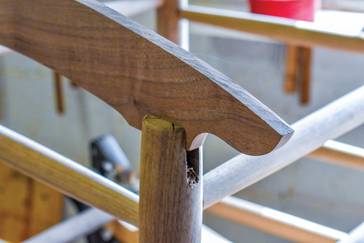
I couldn’t plug the holes and rebore them because the plugs in the incorrect mortises would be flashing neon noticed by anyone who saw the chair. I then wondered if I could I raise the top of the front post in some way? I imagined how various bits of wood could be combined to create that extra 3/4” in height. It would be possible but not without a high level of clunkiness. So I looked at the chair some more, and over the course of an hour of alternately sitting and pacing, I came to realize there was only one real option that didn’t involve throwing the chair onto a burn pile. I had to create a drop in the arms that lowered the back ends 3/4” before continuing on the level to the front post.
Resolution
The long diagonal stick is the back post story stick, and you can still see the incorrect placement of the arm mortise above the corrected placement.
I believe that building by eye and my approach to shop problems are two sides of the same coin. Neither relies on any exterior instrument or text or measured drawing. Both rely solely on the educated judgment of the maker. Are the posts correctly aligned? Does the little fillip at the ends of the arms conform to the chair’s aesthetics? In both instances, I relied on what my experienced gut told me.
But I know that not every woodworker is comfortable relying on his/her uncorroborated judgment to such an extent. Like Joe Graham, I’ve had many students in my chairmaking classes who balk at the idea, preferring squares and rules and straightedges, and I would never say that my approach is the only approach or the best approach. I just know that it works for me, probably a result of a personality that is, in general, not too comfortable with rules and regulations.
Learn to Weave
There are a number of good books explaining how to weave a splint seat, among them are two of mine: Authentic Shaker Furniture and Chair-Making Simplified as well as The Caner’s Handbook by Bruce Miller and Jim Widess.