We may receive a commission when you use our affiliate links. However, this does not impact our recommendations.

True to form. This mahogany storage chest was designed to reflect the distinctive style of California architects Charles and Henry Greene.
Classic design elements combine to create a new design.
Seven years ago I made my first piece of Greene & Greene-style furniture, a coffee table of my own design. It contained several elements the Greenes commonly used: cloudlifts and ebony pegs. As with many pieces inspired by their designs, it is somehow lacking.

It’s all in the details. Proud finger joints, ebony plugs, cloudlifts and overall attention to detail are hallmarks of Greene & Greene furniture. Here they are combined with pleasing proportions to create a new work that honors the originals.
While their design elements are easily appropriated, there is something more elusive in using them to create a cohesive whole. Slapping on cloudlifts and ebony pegs doesn’t automatically create inspired, or even good design. There is no substitute for experience – aiming high and sometimes falling short, as with my coffee table. This piece is farther along the evolutionary scale, due in part to furniture maker Darrell Peart, who helped me work through several details.

It’s all in the details. Proud finger joints, ebony plugs, cloudlifts and overall attention to detail are hallmarks of Greene & Greene furniture. Here they are combined with pleasing proportions to create a new work that honors the originals.
 Charles and Henry Greene established an architectural practice in 1893. Early in the 20th century, a personal style began to emerge. Inspired by Arts & Crafts designs, their work took on the clean lines and exposed joinery of that movement. Charles, in particular, was also influenced by Japanese architecture and Chinese furniture, and these elements began to appear in the Greenes’ work.
The final piece of the puzzle came from a warm climate and casual California sensibility. The Greenes melded these disparate influences into a unique style.

By 1904, they began to create furniture and decorative arts for their commissions and soon were designing nearly every item in the home. Houses and furniture shared a common vocabulary, one that evolved at an amazing rate between 1905 and 1909.
 The Greenes’ symbiotic relationship with builders Peter and John Hall resulted in some of America’s most remarkable residences and furniture.
Blending Old and New
The materials here, as in most well-known Greene & Greene pieces, are mahogany and ebony. Somewhat unusual for this style is the frame-and-panel construction. The decorative inner stiles recall the “sunburst” detail used in windows and doors of the Greenes’ Gamble house. They are inverted in this piece with the angle at the bottom to help anchor the chest visually. These angles make the front and rear panels more visually interesting. They also complicate construction.
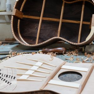
The chest consists of four assemblies: the base, the carcase, the bottom panel and the top. I began with the base, though in retrospect it would have been better to make the carcase first. In the event of any deviation from plan, it is easier to fit base to carcase than vice versa. I concluded with the bottom panel and the top, as both must be fit to the completed carcase.
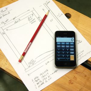
Greene & Greene-inspired Storage Chest Cut List and Diagrams

 Begin With the Carcase
 Begin With the Carcase
It is rare for adjoining surfaces in a Greene & Greene design to be coplanar. The carcase serves as an example. There are four distinct planes: the corner stiles, rails, sunburst stiles and panels, necessitating stock of four different thicknesses. Each corner is actually two stiles joined with a miter along their lengths. I ripped the pairs of adjoining stiles side by side from a wide board to give the look of a single piece and marked each pair.
All rails and stiles are grooved to house the panels. The grooves are centered in the rails but not in the stiles. I used a bearing-guided groove-cutting bit at the router table due to the concave angle on the sunbursts. Because the backs of the frame components align, those faces were used for reference during machining. The grooves in the stiles and top rails are 3⁄8” deep. In the bottom rails, because of cloudlifts, they are 1⁄2” deep. I changed the bearing on the bit to make the deeper cuts.
In the narrow sunbursts the groove depth is 1⁄4“. It would be difficult to cut tenons after the sunbursts are shaped. This argues for cutting tenons first. However, the grooves will be helpful in locating tenons, arguing for cutting grooves first. But the sunbursts must be shaped before cutting grooves. This cycle was broken by cutting the groove on one edge of the sunburst blank, cutting tenons, shaping the pieces then completing the grooves.
For shaping the sunbursts, I made a plywood template. To minimize the amount of smoothing necessary, most cuts were made on the table saw. To do this safely I started with plywood that was significantly larger than the sunbursts. Using a miter gauge I cut the convex angle, then raised the blade and used the fence to make a stopped cut for the parallel edge on the concave side.
Finally, I cut the concave angle on the band saw and used a rasp to smooth that edge. After attaching the template to a sunburst blank with double-stick tape, I cut near the template at the band saw and finished shaping with a flush-trim bit at the router table.

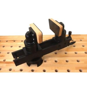
Grooving along. This fixture guides the sunburst stile against the bearing on the router bit and keeps hands at a safe distance from the cutter.
To complete grooving on the sunbursts, I made a fixture to safely hold the pieces. With a sunburst in the fixture I used the already-grooved edge to set the height of the slot-cutting bit. I dry-fit the frame assemblies and made necessary adjustments, resisting the temptation to glue the frame at this point because it would be much more difficult to add the panels afterward.
With the grooves complete, it was time to mortise the stiles. Haunched tenons allow for strong joints without weakening the stiles. The haunch is 3⁄4” long. Creating the mortise involved deepening the grooves in the appropriate locations. I used a 1⁄4” upcut spiral bit at the router table to make the 3⁄4“-deep mortises. I set the fence carefully so the bit was precisely aligned in the groove. A mortising chisel squared the ends.

Handcut haunches. A haunch is cut in the tenon to fill the end of the groove, providing greater strength and a neater appearance.
Next I cut tenons on the rails and stub tenons on the sunbursts. I cut shoulders at the table saw with a miter gauge, using the fence with a stop-block. The tenons align with the grooves so I set the blade height so the top of the blade just met the bottom of the groove. Because the grooves are not centered in the sunbursts, I first cut shoulders on the rails and on the backs of the sunbursts, then lowered the blade to cut the fronts of the sunbursts.
For cheek cuts I used a table saw tenoning jig. Again the grooves are useful in setup, this time providing the lateral setting of the jig. As above, I had to adjust for each side of the sunbursts. I used a Japanese handsaw to haunch the tenons on the rails. I tried to be particularly precise with the crosscut because this will determine if there is a visible gap.
I mitered the eight corner stiles at 45º along the outboard edges after checking the 45 º stop on the table saw, ripping to a width of 27⁄8“. I glued the miter joints with no biscuits or splines – on pieces this thick there is a lot of glue area. I aligned each matching pair of stiles with the mitered edges together, and placed masking tape across the joints in four or five locations, creating a hinge. With the joint tight I applied glue and placed masking tape across the back side of the joint to act as a clamp.

Mitered stiles. Both sides of the stiles at the corners are cut from a single, wide piece. The mitered edges are glued together with tape as a clamp.
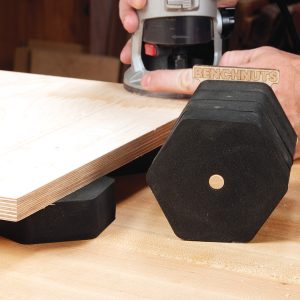
The bottom rails, both front and side, include cloudlifts, a hallmark feature of Greene & Greene designs. These changes in the horizontal line, 1⁄4” in this case, add interest. Shaping each cloudlift by hand is time-consuming, so instead I made a plywood template and used it to mark each rail. After cutting close to the line on the band saw I used a flush-trimming bit to achieve the final shape.
Greene & Greene furniture, and architectural trim, typically has heavily rounded or eased edges. This detail is vital to the correct look. On the most visible edges I used a block plane to achieve a by-hand appearance. On many of the components, however, I used a 1⁄8” roundover bit. Any edge that is visible should be rounded.
It is impossible to imagine Greene & Greene furniture without thinking of ebony pegs. Sometimes used to conceal a screw, sometimes purely decorative, they are a featured element of the design vocabulary. There are 72 pegs and two rectangles in this piece. To determine the sizes and positions of the pegs, I used small paper squares, experimenting until I found a layout I liked, guided by patterns used by the Greenes. I chose three sizes: 1⁄4“, 5⁄16” and 3⁄8“.
Make the Panels
For the 1⁄2” panels in this piece I chose to use solid mahogany. The side panels and center front/back panels were too wide for my jointer, so I chose to flatten the stock using handplanes to minimize the number of glue joints. I hadn’t done this before, but it was quite easy.
Due to the cloudlifts, there are options for the bottom edges of the panels. The easiest of these is to cut the bottoms straight. Because of the cloudlift, however, the grooves in the center portion of the front/back rails are only 1⁄4” deep. This isn’t a problem for the panel but it would force very short tenons on the sunbursts.
Instead, I chose to deepen the grooves to follow the cloudlift, and to shape the bottom edges of the panels to match. This issue doesn’t arise for the side panels where there are no sunbursts. The shallower groove due to the cloudlift isn’t a problem there and the bottom edges of the side panels can be straight.
I cut the panels to size and shaped them using a rabbeting bit at the router table to rabbet the edges.

Rounding rabbets. The backs of the panels are rabbeted to fit the groove in the stiles and rails. Because of the cloudlift, a bearing-guided bit is used to follow the profile of the panel.
This technique works particularly well given the complex shapes of the panels. Sneaking up on the correct thickness with a shoulder plane (and sandpaper where necessary) ensured a snug fit in the grooves. The rabbets must be wide enough to allow for expansion across the grain. I chose 1⁄2“.
With the parts complete it was time to sand and assemble the frame. This is a fussy assembly so a dry run is helpful, and the glue-up is best done in stages. I first assembled the front and back. Because of the shape of the center panels, they can’t slide in after the sunbursts are in place. When the glue had cured, I added the side rails and panels to create a single assembly.
One last step was to add a ledge on the inside edges of the bottom rails. Used to secure the bottom and the base, it runs around all four sides. I used stock about 5⁄8” thick and 11⁄2” wide. It won’t be seen so there is no need to complicate the corners – I simply butted the pieces together and glued them to the bottom rails.
Now for the Base
The finger-jointed base is a dominant design element of this chest. It provides visual interest and serves to anchor the piece. Prominent, proud finger joints such as these were common in Greene & Greene designs during the period of their best-known work.
The assembled carcase determines the lengths of the base members. The fingers are 1″ wide, top and bottom, with 2″ removed between. I used a marking gauge to mark lines on both sides of the stock to allow a chisel to register in the lines.The baseline is the stock thickness plus the amount by which the fingers extend. I used 1⁄8” but now think 3⁄16” would be better. I made sure to mark the baseline only where I would remove material.

Marking, not measuring. Transfering the lines of the finger joints from one piece to the other guarantees the fingers will match.
I cut just to the waste side of the with-the-grain lines at the band saw and made the cross-grain cut with a coping saw. I used a sharp, wide chisel to trim to the lines and didn’t attempt to get to the line in one heavy cut. Thin paring cuts are best.
I marked the width of the 2″ finger using the completed front/back pieces as guides by placing mating pieces on edge on a flat surface with the side piece behind. A marking knife traced the top and bottom edges of the finger onto the side piece. Several light passes are better than a heavy one. Because these joints will show, accuracy is key.
These pieces were cut and pared as before, and I tested the joint often and fine-tuned as needed for a hand-pressed fit. To shape the edges of the fingers, I used a block plane and rasps. With the base together I lightly marked with a pencil where the fingers were proud, and used these lines as a guide for easing edges where surfaces meet. The idea is to round the exposed part without rounding mating edges – that would create unsightly gaps.
With the joinery complete, I cut slots for buttons to secure the carcase to the base. A big believer in overkill, I made eight slots – one on each end and three each, front and back.

No glue on the fingers. The corners of the base are screwed together – a corner block will be glued in later from behind the joint.
The mortises for ebony pegs are cut to a depth of 1⁄2“. I chose not to use glue on the joints as it is too easy to contaminate the exposed end grain, which is very difficult to correct. I screwed the joints together through the peg mortises. I then made substantial corner blocks and glued and screwed them into place on the back side of the corner.
Over-the-top Bottom Panel

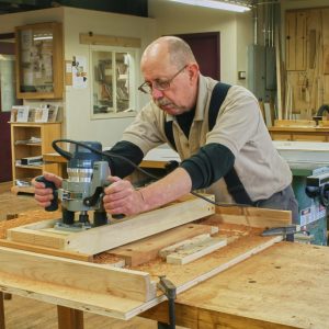
Tip of the tongue. The wide tongue is created with a 3⁄4″ router bit. The straightedge clamped across the top serves as a guide.
If I were trying to make a living at this I would probably have designed a different bottom panel. Most clients wouldn’t be willing to pay for a frame-and-panel bottom that will rarely be seen. However, the Greenes often included such seldom-seen details. For example, the index pins between the halves of the Gamble dining table are highly polished ebony. To this end, I placed a 1⁄4” ebony peg at each mortise-and-tenon joint in the bottom panel. Absent from the original design, I added them on a whim, creating a wonderful surprise for those who open the chest.
This frame-and-panel assembly is much more straightforward than the carcase. There are two rails and four stiles. The two center stiles align with the bottoms of the sunbursts. The joinery is much as before: haunched tenons and mortises at the ends, stub tenons on the two center stiles. Once again, panels are 1⁄2” solid mahogany with edges rabbeted to fit a 1⁄4“-wide groove.
Finishing at the Top
Top panels flanked by proud breadboard ends are another Greene & Greene hallmark. While many breadboards are purely functional, in the Greenes’ hands they became a happy synthesis of function and beauty. In this chest, the inboard edges of the breadboards align with the stiles for a clean, cohesive look.
The top is the most visible part of this chest so I chose stock carefully. I had two wide planks so I was able to make the panel with only one glue joint. Of course, 11″ boards are way beyond the capability of my jointer. To flatten these I used a sled that fully supports one side of the board (even if twisted) allowing the planer to flatten the other face.
The breadboard ends are 1⁄8” thicker than the panel and the length is 1⁄4” greater than the width of the panel. The breadboards attach with 1⁄4“-thick by 3⁄4“-wide tongues on the panels and corresponding grooves, stopped 3⁄4” from the ends, in the breadboards. I made the tongues with a straight bit in my plunge router and set the maximum depth to 3⁄8“.

Tip of the tongue. The wide tongue is created with a 3⁄4″ router bit. The straightedge clamped across the top serves as a guide.
I measured the distance from the bit to the edge of the router baseplate and added 3⁄4“. A straightedge was clamped to the top at the calculated distance from the end, making sure that it was square. I made the cut in several progressively deeper passes, then used a fine-toothed handsaw and chisels to remove 3⁄4” of the tongue at each corner.
For the stopped grooves in the breadboard ends, I used an upcut-spiral bit at the router table. I set the distance between the fence and bit equal to the size of the shoulder below the tongue. It is better to err with a larger distance rather than smaller since it is easier to plane the breadboard level with the panel than vice versa. I marked the fence to indicate where to start and stop cuts and again, made progressively deeper passes. I then test-fit the breadboards, making adjustments to the tongues with a shoulder plane.
Each breadboard has four ebony pegs and one rectangle. The smaller pegs are not centered on the thickness of the breadboard; rather their bottom edges are flush with the larger pegs. I drilled pilot holes through the middle of the bar mortise and through the 3⁄8” mortises for screws to secure the breadboards. The outboard holes are elongated to allow for expansion/contraction of the top. The breadboards are glued only along the center 6″.

Handsome hinges. Shop-made wooden hinges, mortised to the top and screwed to the back, reflect the finger joints in the base.
For maximum authenticity, “stacking” small butt hinges to create a continuous hinge, is called for. However, I thought this piece required something more decorative. I considered strap hinges but they are more rustic than I wanted. I decided to make wooden hinges, which opened up an infinite range of design possibilities. My design evokes the finger joints in the base.
Finishing Up
I like the look of mahogany as it darkens naturally, with no stains or dyes, so I chose to finish with Waterlox Original Satin, a wiping varnish that is foolproof. It looks great and is easy to maintain and repair. For this project, I finished the four subassemblies separately.
I wiped on the first coat and wiped off any excess after a few minutes. Don’t let it sit too long or it will get sticky. I allowed the first coat to cure and scuff sanded with #400 grit. I then wiped on several more coats, one per day, with no sanding in between. After the last coat cured for a few days, I very lightly sanded with #1,000 grit. This reduces the sheen and gives the surfaces a terrific feel.
After waiting several additional days, I assembled the components. First was the bottom panel. I put it in place and drilled pilot holes through countersunk holes in the ledge. I used #6-11⁄4” screws. With the bottom in place, I attached the base with buttons made from mahogany scrap. I drilled pilot holes through the holes in the buttons, and used the same size screws for this step.
Finally, I attached the top. For the hinge pins, I cut brass rod to length, then filed and polished the ends. After positioning the top, I tapped the pins into place; no need to secure them, friction is my friend.
Most Greene & Greene pieces I’ve made are similar to items designed by the brothers. This piece is unlike anything that I’m aware of in their canon. It was enjoyable to work in the style but outside the box, to solve the design and construction problems without benefit of historical solutions. It’s too soon for me to have any perspective about the piece, but my wife says it’s her new favorite. And that’s about as good as it gets.