We may receive a commission when you use our affiliate links. However, this does not impact our recommendations.
Onboard Storage for Tools, Accessories, and 150 Pounds of Ballast
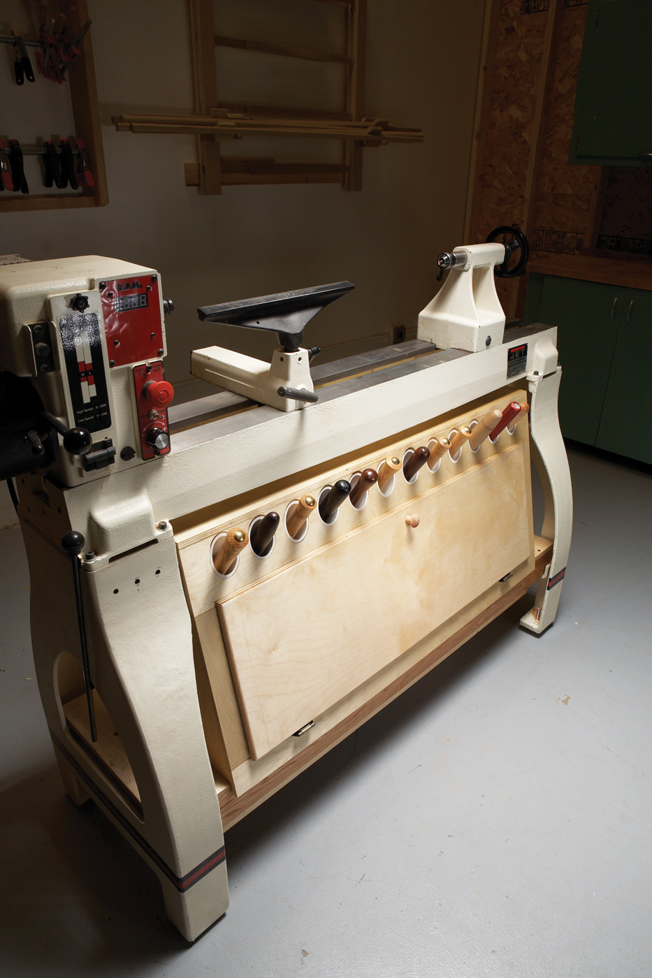
After several years of making lots of shavings and dust with a small, underpowered lathe, I decided I deserved an upgrade. My new lathe has big capacity, ample power and electronic variable speed—important features that my old lathe lacked. Only one thing was missing: an on-board storage cabinet for all of my turning tools and accessories.
My new lathe has cast iron legs with brackets that were perfect for adding such a cabinet. I choose this design because it also includes a ballast box that holds up to 150 lbs. of sand. Adding ballast to dampen vibration and lower a lathe’s center of gravity is always a good practice, especially if you plan to turn large-diameter bowls as I do. Actually, you could opt to build only the ballast box. The tool box simply nests on top of it.
This design easily adapts to lathes with open stand bases—just extend the beams to rest on the end rails.
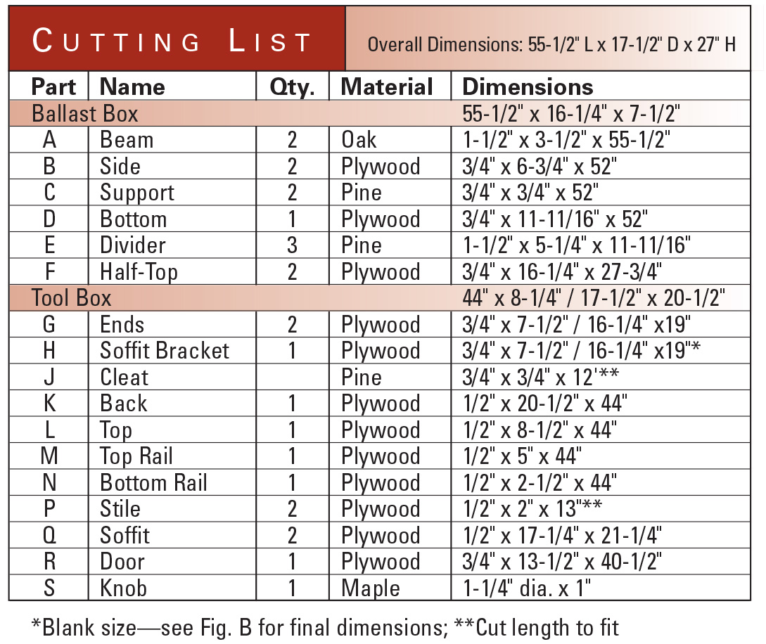
To build both boxes, you’ll need one 4×8 sheet of 3/4 in. plywood, one 4×8 sheet of 1/2 in. plywood and 15 bd. ft. of 8/4 oak for beams (or one 10 ft. 2×4 if you decide to substitute dimensional lumber). You’ll also need a 4 ft. 2×6, a 6 ft. 1×6, three 10 ft. lengths of 2-in. PVC pipe, a couple 6 ft. lengths of foam pipe insulation, hardware for the door and three 50 lb. bags of sand. Of course, unless your lathe has the same legs and a 42 in. bed, you’ll have to adapt this design to fit.
Additional Reading: Check out all of our shop project articles.
More at the lathe: Take our eLearning course from renowned turner Jimmy Clewes.
Cutlists and Diagrams
 Build the Ballast Box
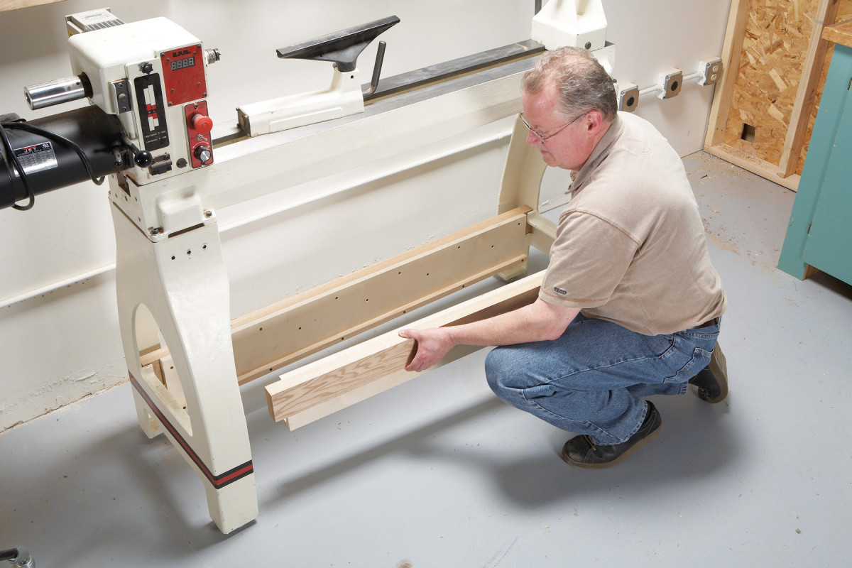
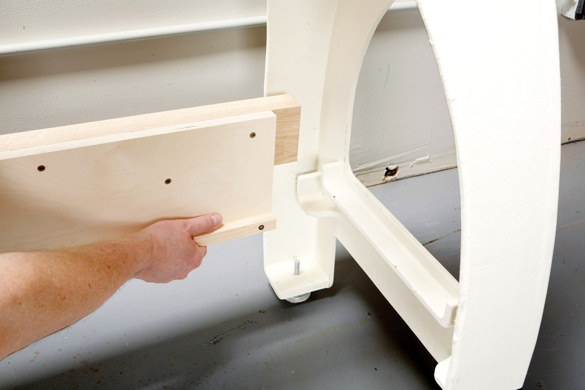
1. Every lathe benefits from additional mass to dampen vibration. These legs have castin brackets for beams, the perfect setup for hanging a ballast box. On an open stand, the beams can rest on the end rails.
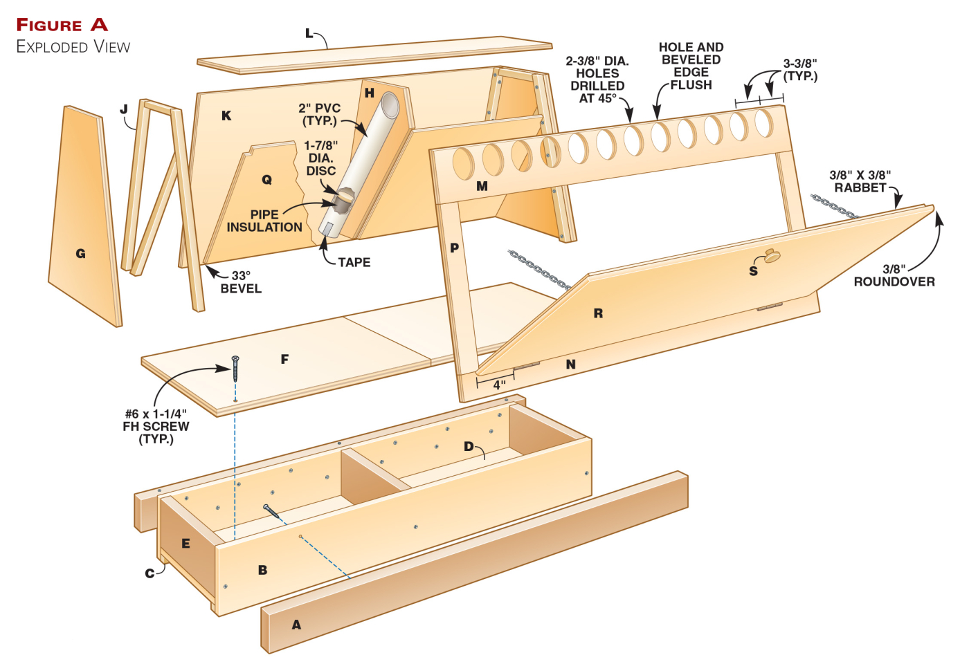
Cut the beams, sides and supports and glue and screw them together (Parts A-C, Fig. A). Hang these assemblies from the leg brackets (Photo 1).
 Then install the bottom (D) and the dividers (E).
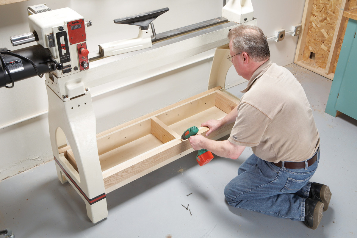
2. Assemble the box in place to make the ballast compartments as large as possible. Drop in the bottom after installing both beam assemblies. Then install the dividers.
Once you’ve added these parts, the assembly can’t be removed from the lathe intact (Photo 2). Use glue only if you want the installation to be permanent.
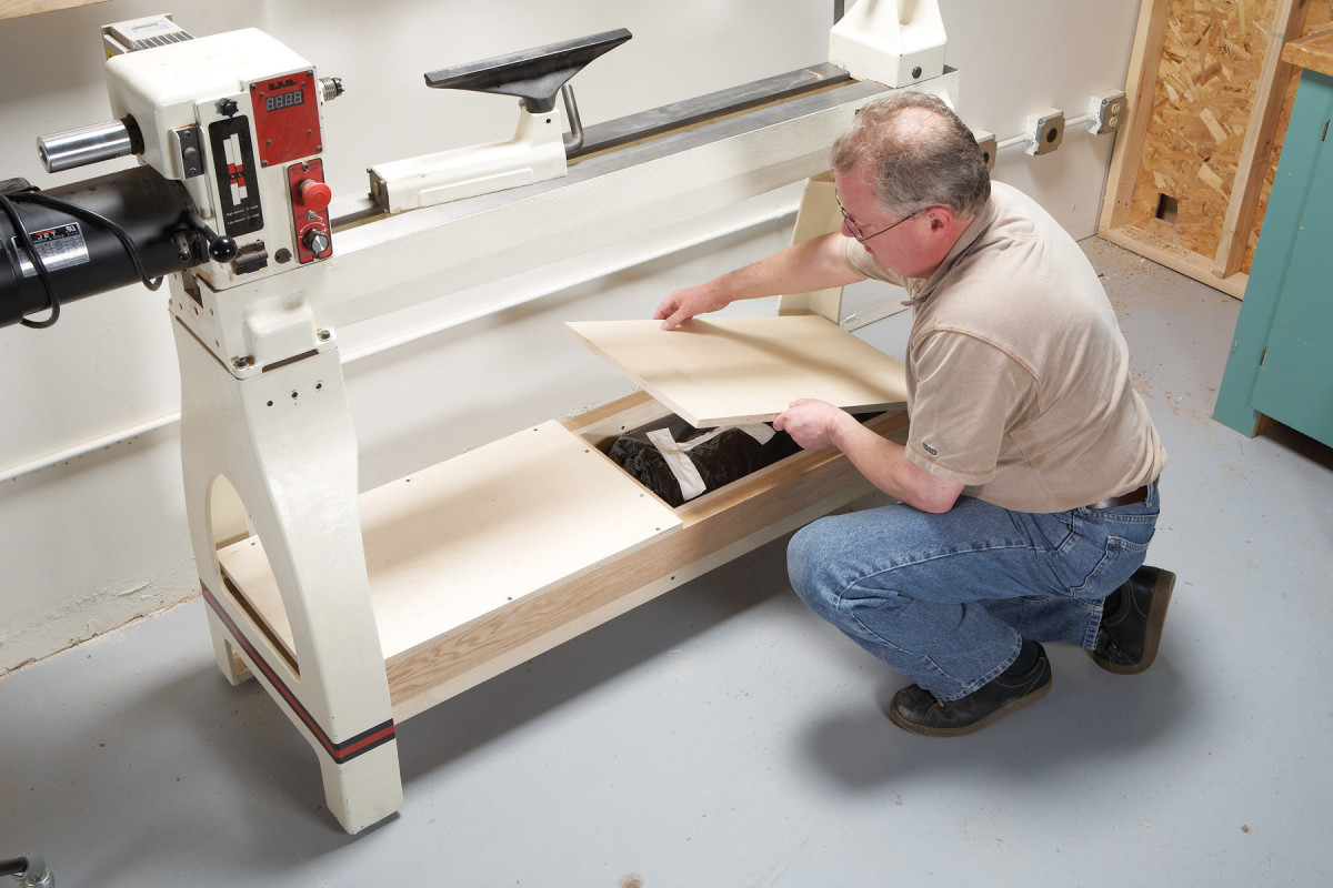
3. Place sand-filled trash bags in each compartment. Install the top in two pieces—a single piece won’t fit between the legs.
Line the ballast compartments with heavy-duty plastic (at least 3 mil. thick) and then pour in the sand. Seal the bags and install the top (Photo 3).
Cut Pieces for the Tool Box
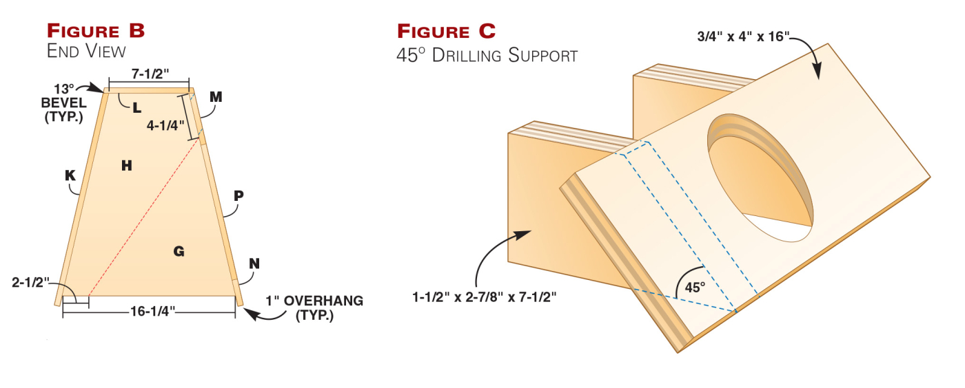
Cut the ends (G) to final size (Fig. B). I used a tapering jig to cut the sloped sides. Cut the Soffit Bracket (H) at the same time—it’s an end piece with one additional cut. Attach cleats (J) to the ends. Make sure all the edges are flush.
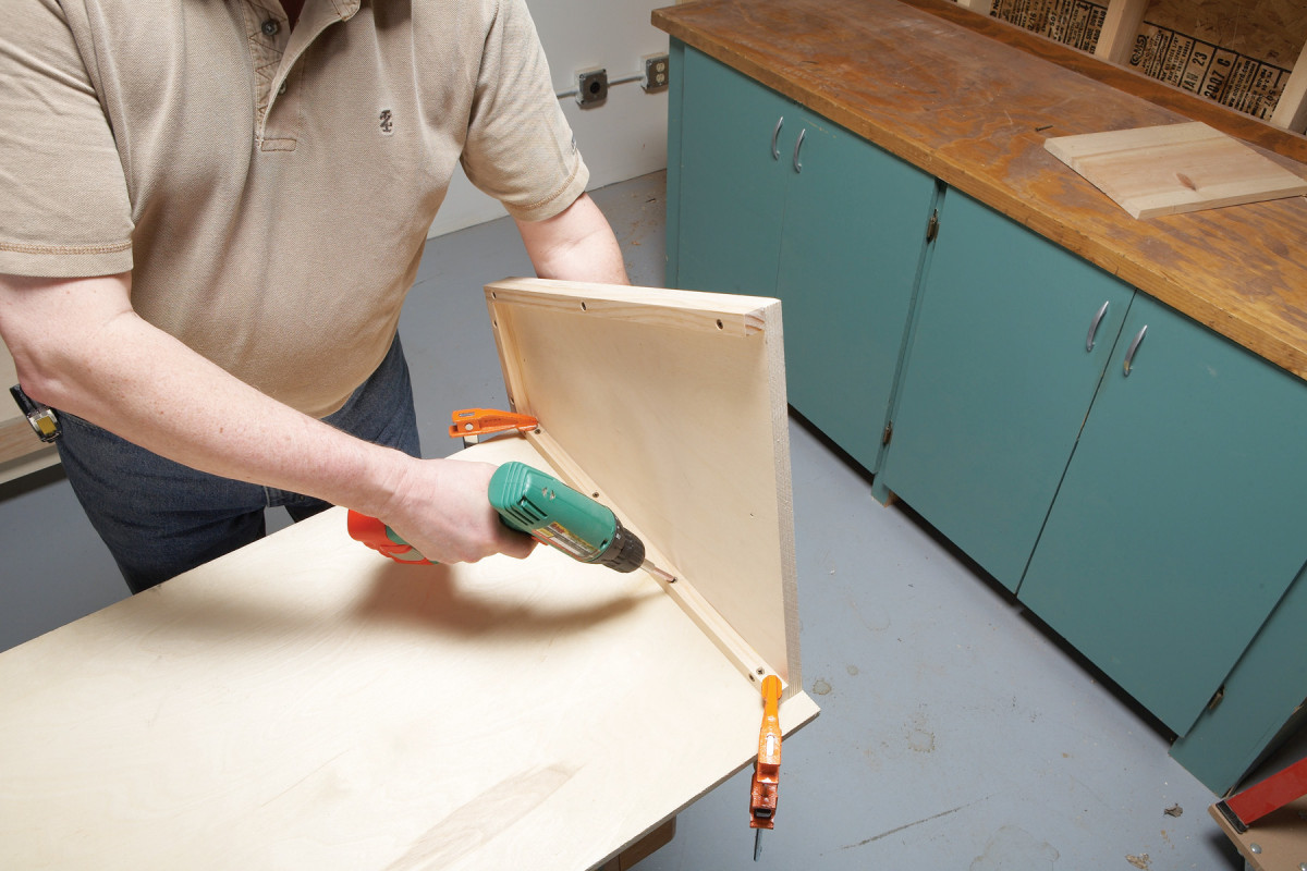
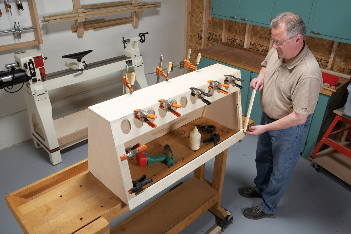
4. Start assembling the tool box by fastening the ends to the back. The ends are patterned after the lathe’s leg and sized to fit between the ballast box and the lathe’s bed.
Crosscut the 1/2 in. plywood sheet at 44 inches. Then cut the back, the top, the top rail and bottom rail (K-N) from this piece. Bevel the top edges of the back and the top rail at 13 degrees, to match the slope of the ends. Bevel both edges of the top at the same angle. Test fit the pieces to make sure the top’s beveled edges are flush with the faces of the back and the top rail. Then glue and screw the ends to the back (Photo 4). Note that the back extends 1 in. below the ends.
Drill Holes for the Tool Sleeves
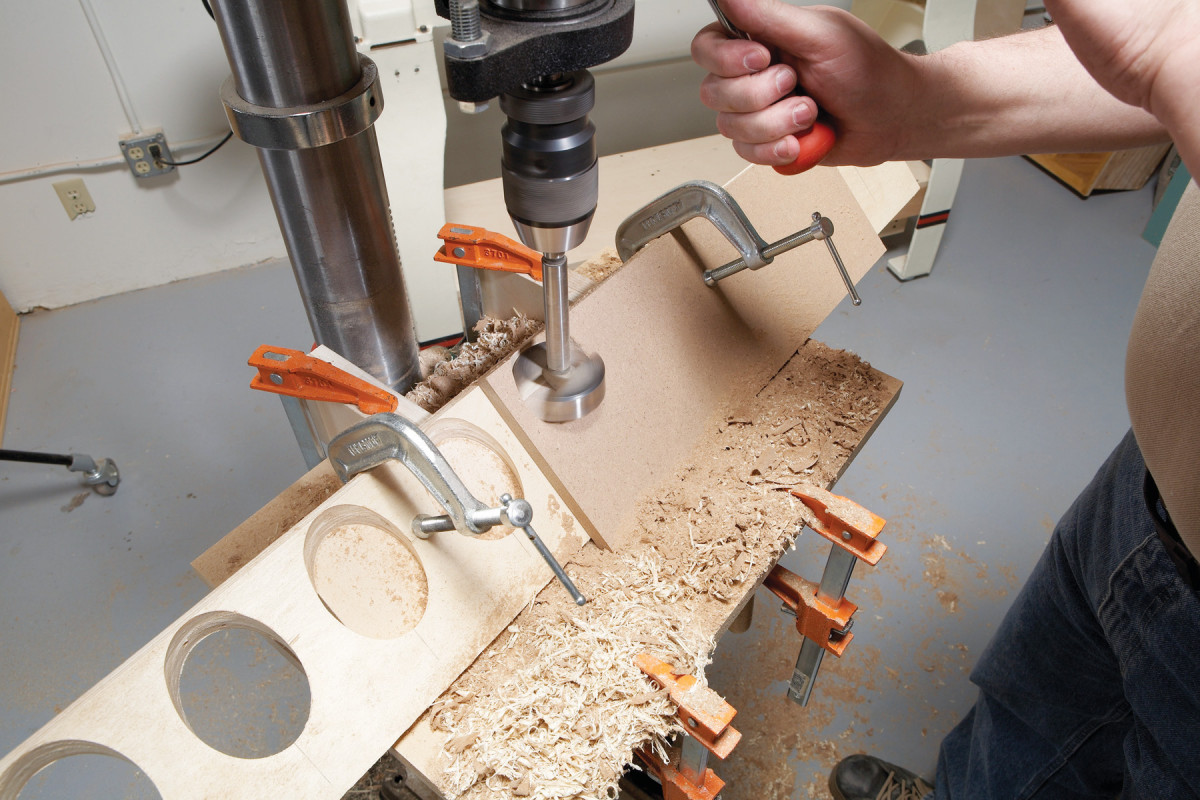
5. Use a 45-degree support to drill angled holes for tool sleeves in the top rail. Position the rail so the holes start at the rail’s beveled top edge. Clamp on a sacrificial board to eliminate tearout.
To allow the tool sleeves to angle to the back corner of the box, the holes in the top rail have to be drilled at a 45 degree angle. I cut these holes on my drill press, using a shop-made 45-degreeangle support (Fig. B) and a 2-3/8-in.-dia. Forstner bit (Photo 5). Here are some tips for drilling these holes
- Drill at a slow speed (500 rpm, or less).
- Install a sacrificial board on top of the workpiece. Because of the steep angle, the bit may chatter until the center spur is engaged—especially if the bit has sawtooth edges. The sacrificial board stabilizes the bit before it cuts into the workpiece.
- Reposition or replace the sacrificial board before drilling each hole
- Drilling these holes requires a 4-in.-long quill stroke. If your drill bottoms out too soon, stop the drill, loosen the chuck and extend the bit. Rechuck and make a second plunge.
Assemble the Tool Box
6. Assemble the tool box. First fasten the top and bottom rails to the ends. Then install the top. Add the stiles last.
Glue and screw the front rail and bottom rail to the ends. Then install the top. Fasten it to the ends with glue and screws. Glue and clamp it to the back and the front rail. Finish by gluing on the stiles (P and Photo 6).
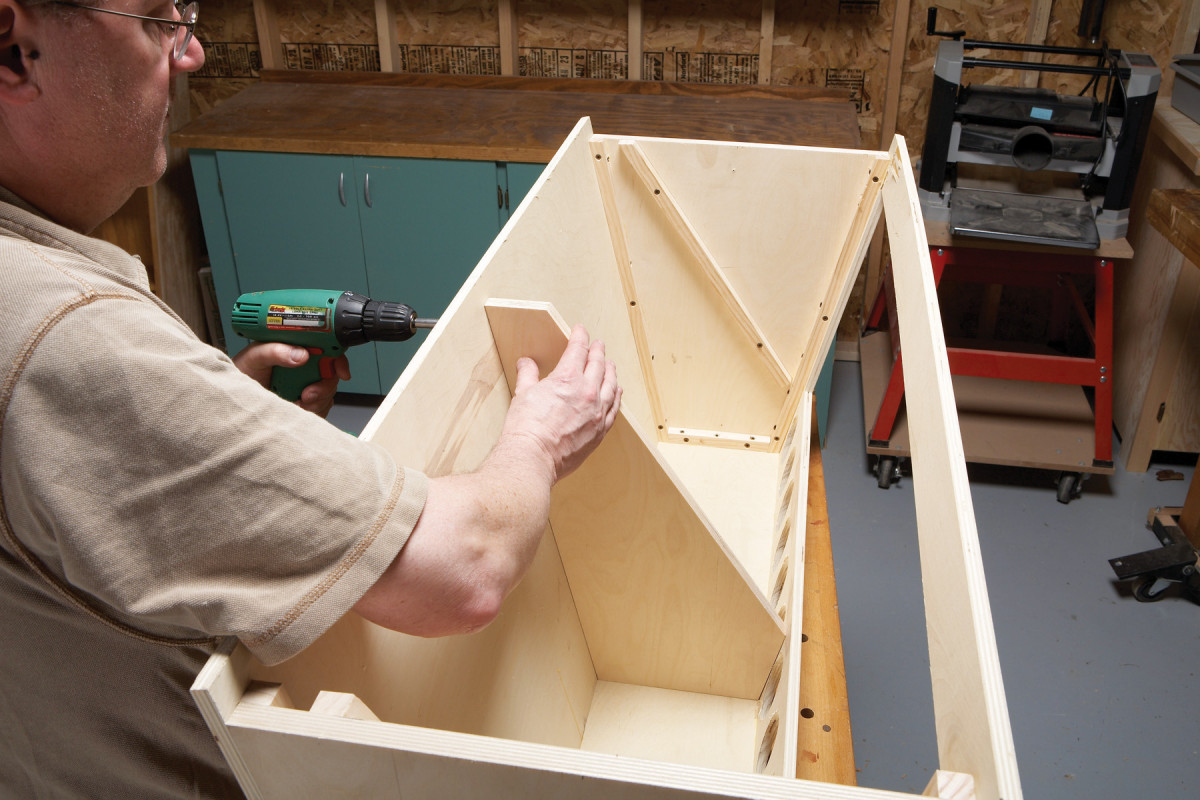
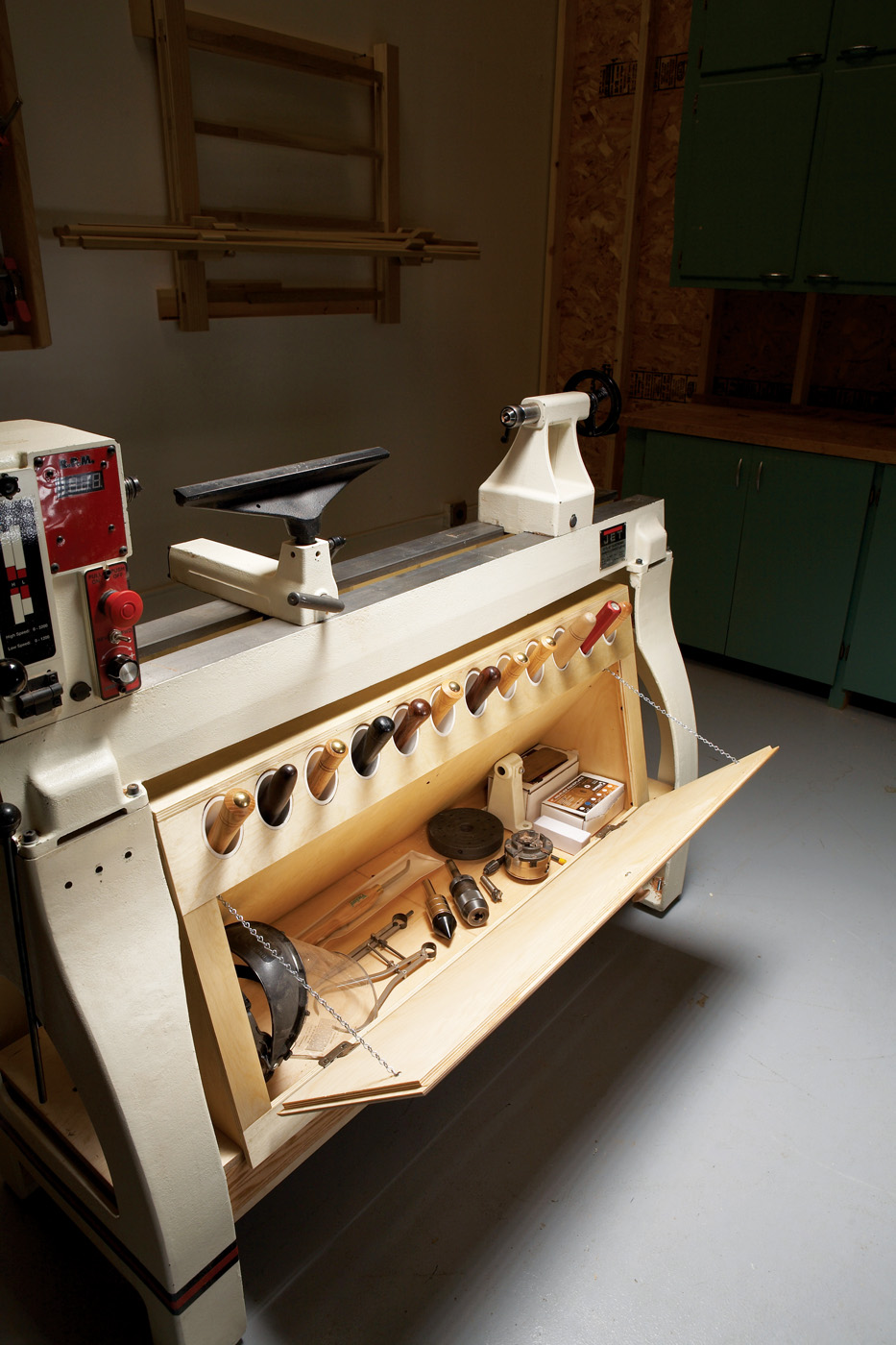
7. Install the soffit bracket (an end piece that’s cut diagonally) and cleats. The tool box has no bottom because it nests over the ballast box—the overhanging back and bottom rail hold it in position.
Use the soffit bracket to locate cleats on the ends for fastening the soffits. Then glue and screw the bracket in place (Photo 7).
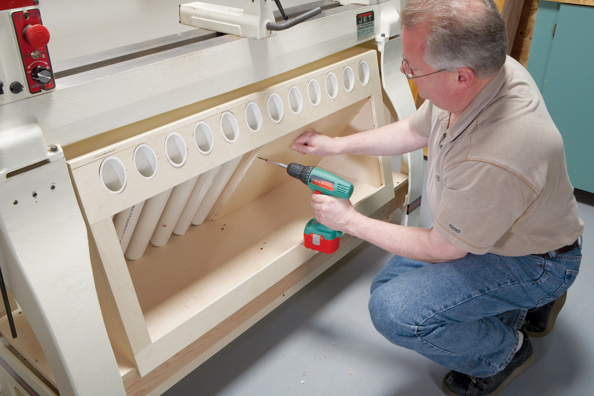
8. Cut the tool sleeves to fit and install the soffits. The tool sleeves (made from 2-in. PVC pipe) are only friction-fit, so they can be removed and reinstalled without removing the soffits.
Slide the tool box into position on the ballast box It’s held in place by the overhanging back and bottom rail. Cut the tool sleeves to fit the box. I found that cutting the front at a 43 degree angle fit better than the 45 degree angle I expected. Go figure. Install the soffits (Photo 8).
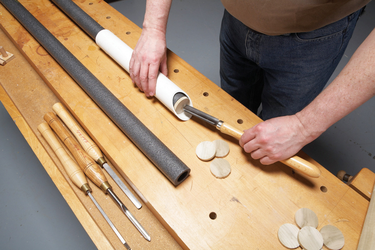
9. Fill the tool sleeves with pieces of foam pipe insulation to make all your tools protrude equally. Use a wooden disc as a stop. Hold the foam in place by taping across the bottom of the sleeve.
Decide how far you want your tools to extend beyond the tool sleeves. Then fill each sleeve accordingly to make them fit (Photo 9). I turned a dowel to make the discs that serve as tool stops. Adding or subtracting discs is an easy way to adjust the tool heights.
Final Details
Cut the door to final size. Round over the edges and rout a rabbet all around the back. Install the hinges and mount the door. The self-closing hinges I used were designed to mount on a 3/4-in.-thick face frame, so I added blocks at the hinge locations to build out the bottom rail. Install the knob and add chains to keep the door from falling too far open.