We may receive a commission when you use our affiliate links. However, this does not impact our recommendations.
 As you gain experience with SketchUp there will come a day when the light bulb will go on and you will realize that you need a strategy for naming components, organizing and naming scenes and layers, and for dimensioning and creating shop drawings. I hope in this multi-part series to help you realize this sooner and with less pain.
But first I want to start with a couple of rules I live my SketchUp life by. These are in addition to the six rules for modeling I provide in my Beginner’s SketchUp Webinar.
1. Don’t use groups, except perhaps on a very temporary basis e.g. when grouping a collection of components to move around the model. Even in this case it is better to make the collection a temporary component. Groups have bad side effects, many of which are hidden from the user but will come back to bite him/her later. Think of groups as being evil – because they are!
 2. Avoid hierarchical components. I can’t speak for other areas of SketchUp use such as architectural design, mechanical design etc., but I have never seen a situation in woodworking where hierarchical components are needed or where another mechanism doesn’t work better. Hierarchical components are seductive, but there is no need for them, and they often give many plugins problems.
3. When creating scenes use Parallel Projection and one of the standard views. This is primarily because you can print scaled shop drawings from the scenes and you can make accurate measurements in the shop from the drawings. Not to mention that this is the way professional engineers and draftsmen would do it. The exception is the first scene(s) which are intended for the “customers” viewing benefit; they should be Perspective or Two Point Perspective and textured.
 4. When naming components choose names that are industry standards. For example, when naming the parts of kitchen cabinets use names like stile, rail, panel, face frame, plinth. In furniture use names such as apron, muntin, baluster, cornice, bracket foot, dust panel etc. Doing so helps others to read your shop drawings and saves you from having to make up creative names. You can search the web for woodworking terms or woodworking parts and find numerous good glossaries. Wikipedia is always a good place to look if you need to know the difference between terms such as muntins and mullions. The latter two terms are often incorrectly defined in many glossaries.
An Overall Look at My Strategy
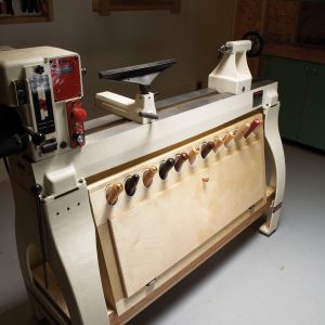
Since this is my post, it will be my strategy we explore. But you might want to look at others and in the end choose one that works for you. I make liberal use of scenes and layers particularly because scenes will become the individual shop drawings that I print out to take to the shop. My scenes usually start with three standard composures: one complete model in perspective view and textured; one front parallel projection view with overall dimensions; and one side parallel projection view with overall dimensions. The remainder of my scenes will almost always be in parallel projection view as described in rule 3 above. Enlarge the previous images by clicking on them and notice the scene tabs and dimensioning.
 The image at left shows you the Scenes and Layers dialog boxes viewed as lists. Note that Scenes tabs, if there are a lot of scenes, must be scrolled to access all scenes. However, you can use the Scenes dialog box in list form more readily, just as you can the Layers dialog box.
If you look closely at these lists you will notice a few of my strategy elements which we will dig more deeply into next week. Notice a lot of layers prefixed with the capital letter Z. I almost always put dimensions on their own layer, often with the same name as the part(s) I am dimensioning prefixed with Z-. What this does is forces all the dimension layers to the bottom (or top) of the list when I alphabetize the list with the Name tab. Here are a few example pairs of layers: Top and Z-Top; Stiles and Z-Stiles; Sides and Z-Sides. This will become clearer in subsequent installments of this series.
Also notice that a lot of scenes have the same name as the layers, for example, scene Back, layer Back and dimension layer Z-Back. This is both intentional and insight into what a scene really is. This is an important concept so read this a few times: A Scene is a collection of Layers. Using the latter example we can think of a scene as an equation:
Back = Back + Z-Back (Scene Back equals Layer Back plus Layer Z-Back)
or
Perspective = Back + Drawer Back + Drawer Bottom + ……….. + Stiles + Top + Upper Rail
 In other words when you define a scene you are defining a set of visible layers that make up that scene, and when you select a scene you are making only those scenes visible. Of course Layer0 is always visible in every scene and is always the active layer (black radio button). Later in this series we will learn what else goes into making a scene, but this is the important concept.
Another element of my strategy can be seen in the Drawer….. layers. When designing or building a piece of furniture we usually think of the superstructure as the carcass. Carcass parts (components) I usually put on a layer named after their name and often plural. For example Legs; the Legs layer contains two instances for Front Leg (Left Front Leg and Right Front Leg) and two instances of Back Leg, hence the plural. But I don’t precede the Legs layer with Carcass because it is the main assembly and goes without saying. A sub-assembly on the other hand is usually preceded with its sub-assembly name, hence Drawer Back, Drawer Bottom, Drawer Sides etc.
Contrast the Bedside Table Layers dialog box with the Shaker Tall Clock Layers dialog box above right. In this case there is no definable carcass and so each sub-assembly name precedes a layer name; Feet, Base, Waist and Hood. This actually makes sense if you think about how you build the table and the clock in the shop. The table has a carcass which you build first and then the drawer. The clock is built as sub-assemblies and each sub-assembly is assembled in order of feet, base, waist and hood to for the clock.
In a later installment you will see another example of Layer naming strategy for a house design. There I precede the layer name with Cellar, 1st Floor and 2nd Floor. My strategy for Components, Dimensioning, Scenes, Layers & Naming is not arbitrary, but as you will see, helps me with modeling efficiency, shop drawing generation and readability, especially for large complex models. We will get into the details beginning next week.