We may receive a commission when you use our affiliate links. However, this does not impact our recommendations.
 Once you understand the anatomy of a handplane, you’ll be well on your way to using it with success.
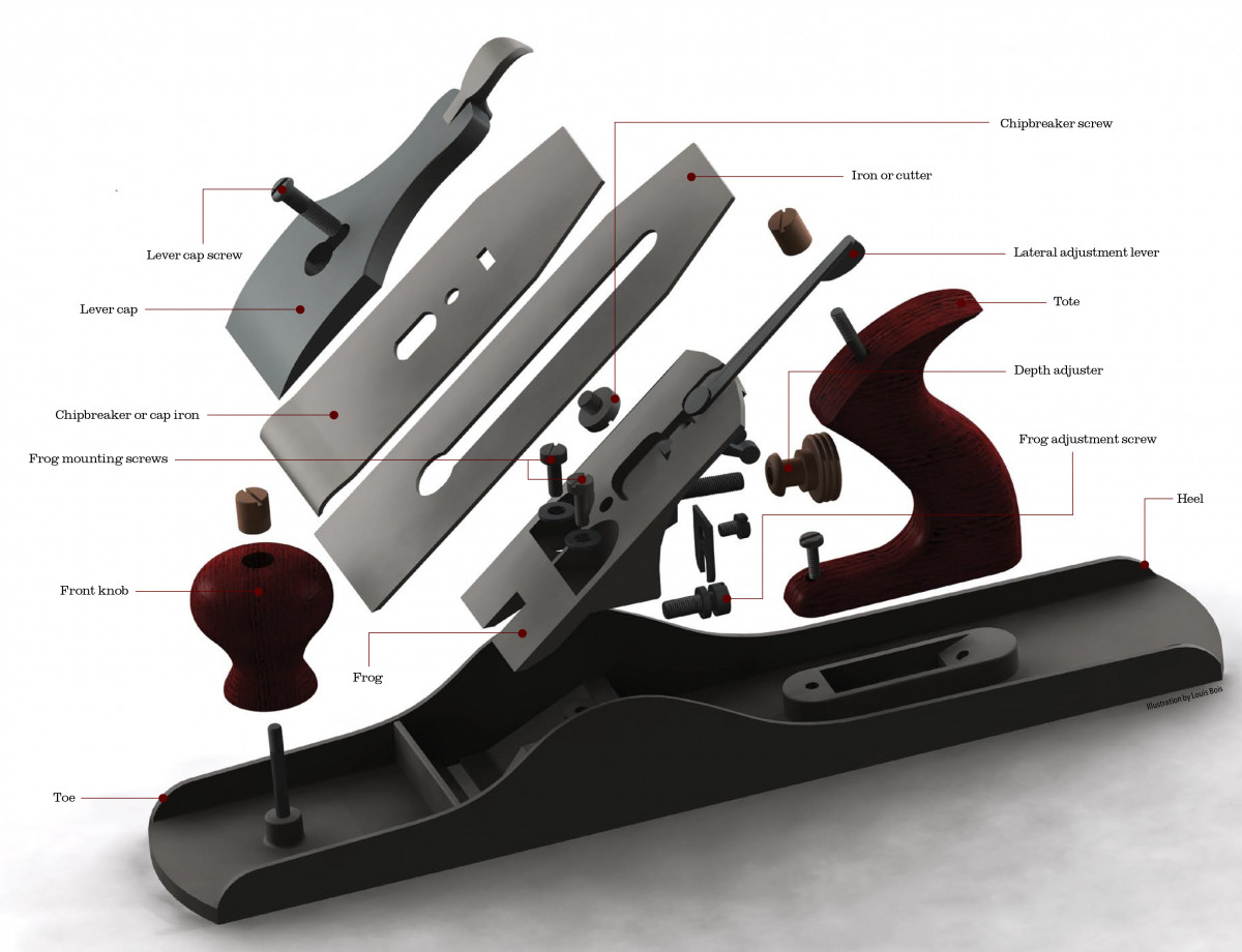
[View the full-size exploded view of a handplane here]
Handplanes are the king of woodworking tools in that they are the most versatile tool in a shop. They do so many varied jobs, that the more you know how to use planes, the more planes you own. The converse is true. If you own just one, there is a good chance you do not know how to use it.
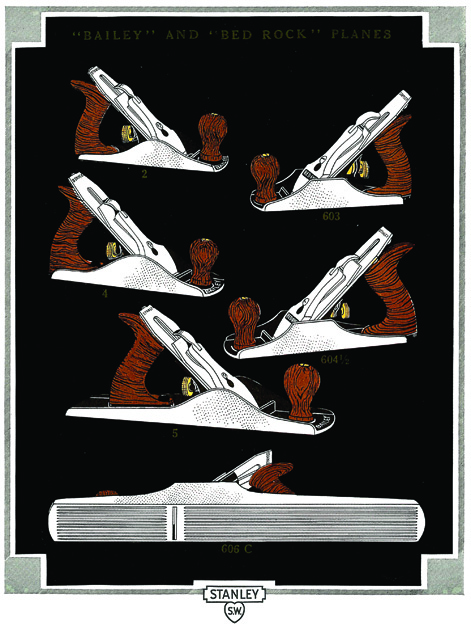
Stanley made bench planes in many sizes from the diminutive No. 1 to the massive No. 8 jointer plane.
If you do not know how to use a plane, you are not alone. In fact, when history judges those of us who teach and write about woodworking, it will be harsh. We bear responsibility for the loss of knowledge of handplanes. For thousands of years these tools have been the mainstay of every woodworking shop, and in a matter of decades we permitted this knowledge to almost disappear. These days, the handplane is used more frequently as a logo on woodworkers’ business cards than in their shops.
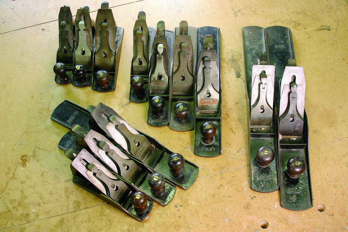
Some of the many bench planes produced by Stanley. The three planes shown directly above are Bed Rock planes – the top of the line. The rest of the planes are grouped by function. From left to right: smooth planes, jack planes and jointers.
I experience this lack of knowledge directly in every class I teach. Our tool list specifies a handplane, “either smooth or jack, such as a Stanley No. 4 or No. 5.” Students putting their tools together frequently call and ask for clarification. One recently repeated what I have heard many times: “I’m a professional woodworker and I don’t know what a ‘smooth’ or a ‘jack’ is.”
Students frequently ask us to show them how to adjust the plane they brought. When they go to work, we frequently observe them struggling with their planes. It is not uncommon for us to find the blade upside down, or even the chipbreaker mistaken for the blade. The purpose of this article is to describe the basics of handplanes starting at the most nitty-gritty level. Until you understand these basics, handplanes will remain a mystery.
A History Lesson
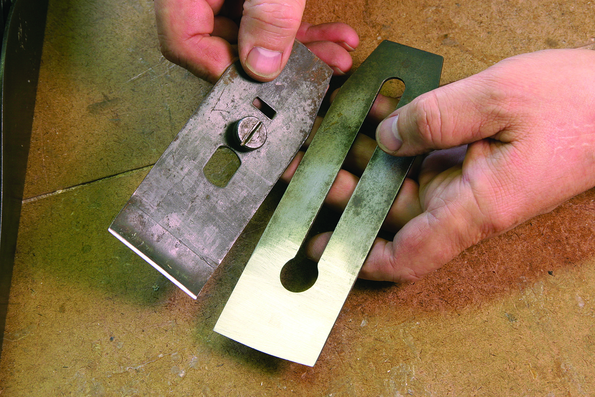
The iron (right) and the chipbreaker, sometimes called the cap iron or back iron. The chipbreaker was designed to prevent the wood from tearing out ahead of the iron’s cutting edge.
The basic handplane we recognize is referred to as a “bench plane.” The quest to develop cast iron bench planes began in the 1800s. Prior to that, most planes were made of wood. Cast iron planes were deemed more desirable, because they could be easily mass produced, and would hold up longer. Although a lot of people had tried making cast iron planes, Leonard Bailey of Boston, Mass., made a technological breakthrough by inventing the removable frog. This device allowed for more easy and accurate adjustment. In 1869, Bailey sold his patents for cast iron planes to the Stanley Rule and Level Co., which for a long time continued to call its planes “Bailey Patent.” The term is still used and understood today.
For many decades, Stanley produced high-quality iron planes in prodigious quantities. By 1897, the company had sold more than 3 million planes. Until the 1930s, the company introduced numerous improvements to Bailey’s original design. Quality began to decline after World War II, and this decline accelerated after 1960. For that reason, the best of Stanley’s products are referred to as “pre-war planes.” These are the examples preferred by the most experienced handplane users.
Stanley numbered its line of bench planes No. 1 through No. 8. The number designates the plane’s size and purpose. No. 1 through No. 4 are smooth planes. However, the No. 1 and No. 2 are so small as to be impractical, and so we will ignore them. No. 5 and No. 6 are jack planes, while No. 7 and No. 8 are both jointers.
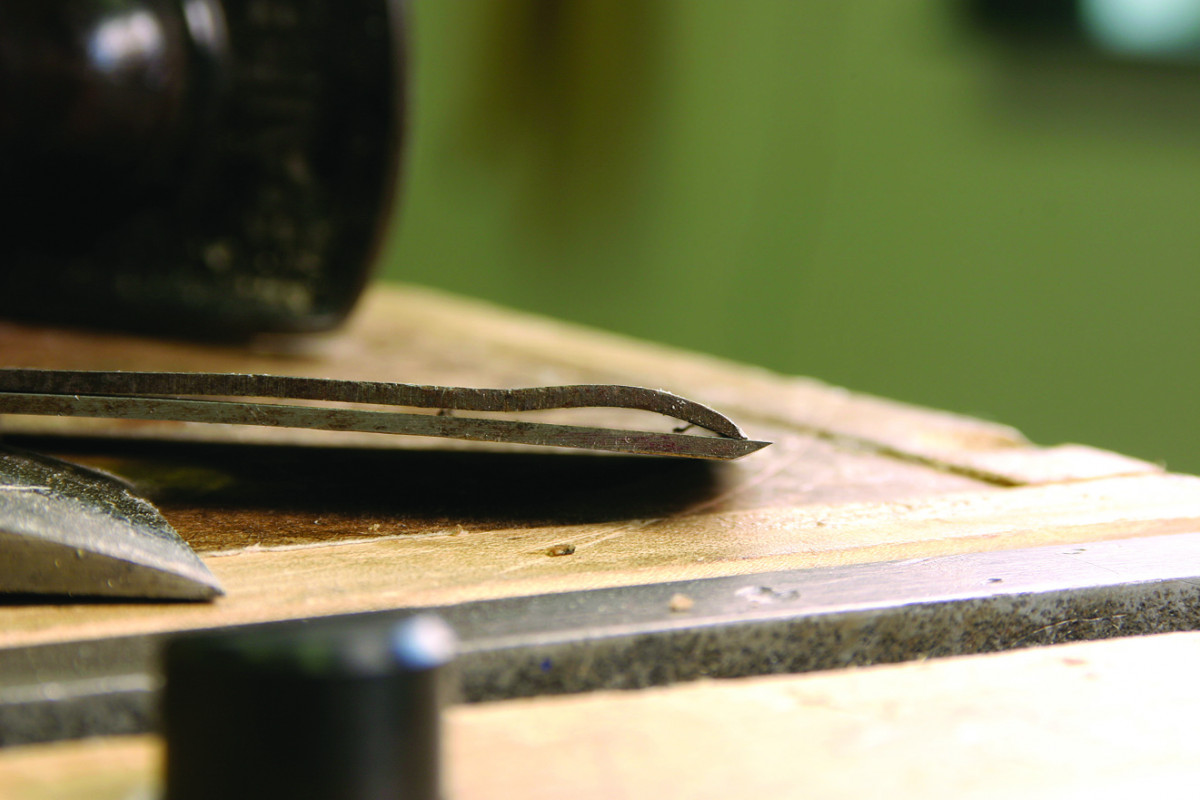
The assembled chipbreaker and iron. When the plane’s iron cuts a shaving, it immediately is deflected up and kinked by the chipbreaker. The shaving is ejected out of the plane.
The words smooth, jack and jointer describes a plane’s most common purpose. A smooth plane is typically used for finish work. The word jack is a bit archaic, but once designated things that were used for heavy work. Thus, a jack plane is designed for heavy stock removal. Like its powered namesake, the jointer straightens the edges of boards, frequently in preparation for gluing.
There are three other less common bench planes in the series, designated No. 4 1⁄2, No. 5 1⁄4, and No. 5 1⁄2. The No. 4 1⁄2 is a wider smooth plane. The No. 5 1⁄4 is a smaller jack than the No. 5, while the No. 5 1⁄2 is larger.
Stanley also produced a Cadillac series of planes that it sold under the name Bed Rock. These are high-quality tools and rank among the best handplanes ever produced in the world. The Bed Rock planes used the same numbering system as Stanley’s Bailey Patent planes, except that the plane’s number was preceded by the number 60. Thus, a No. 604 is a Bed Rock smooth plane, while a No. 605 is a jack.
After Bailey’s patents expired, other companies produced copies of Stanley planes. Some of these companies include Sargent, Keen Cutter, Millers Falls, and Record. Some even used numbering systems that mimicked Stanley’s.
Plane Anatomy 101
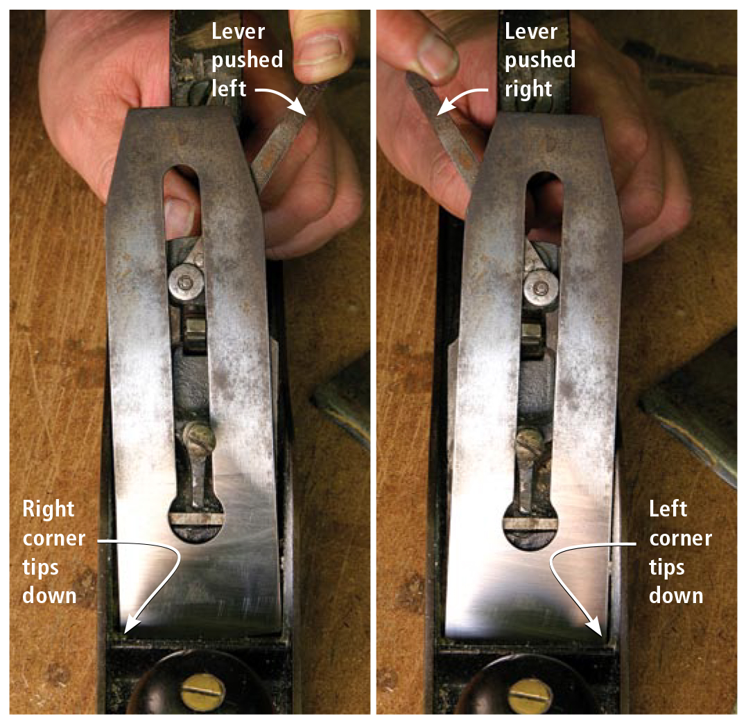
The lateral adjustment lever keeps the cutting edge parallel with the sole. When you move it all the way left (from the operator’s perspective), the right corner of the iron tips into the work. When you move the lever left, the opposite effect occurs.
A bench plane is essentially a mechanism for securing a chisel-like blade so it can take a controlled cut. The tool also permits the cutter to be adjusted to a desired setting. Since at least the time of the ancient Egyptians, all handplanes have had certain elements or parts. The main part is the body, which on a wooden plane is also called its stock. The bottom surface of the body that runs on the wood is the sole. The front end of the body is the toe, and the rear the heel. The sole has an opening in it through which the cutting edge projects. This opening is called the mouth. The handle that is used to push a plane is the tote, and sometimes there is a knob. The blade is also called the iron or the cutter.
In a wooden plane, the mouth is the bottom of a larger opening called the throat. The cutter is secured on the back surface of the throat, called the bed, by a wedge. The cutter had to be adjusted by a light hammer. Bailey’s genius was to create a whole new way of holding and adjusting the cutter. His method relied on a removable 45° bedding platform called a frog.
A Bailey-type plane’s cutter is secured to the frog, which is then secured to the body. The frog also includes two important adjustments, and because it is secured to the body, it is itself adjustable. As a result, a Bailey-type plane is very easy to set up and very accurate. However, it is easier to understand the adjustments if you understand how a plane works.
How it Works
The plane blade’s cutting edge projects below the sole. When the plane is pushed forward, this sharp edge engages the wood and severs a shaving. Imagine a chisel being pushed over wood. While its sharp edge would engage the wood, the shaving would quickly become long enough to ride up the chisel’s inclined body. Then, instead of cutting, the chisel would begin to act as a lever, lifting the wood. The split would extend ahead of the cutting edge, so instead of being cut, the chip would tear away from the board. The result would be no control, and the resulting surface would be quite rough.
That is where the sole of the plane comes in. The flat sole ahead of the cutting edge holds the wood down and prevents it from being torn loose by a levering action. Because it cannot lift the chip ahead of it, the cutter shears a continuous shaving. That shaving then passes up through the mouth and is ejected from the plane.
Advent of the Chipbreaker
For millennia, the sole of the plane was the only prevention against tearing. In the 18th century, plane makers developed the chipbreaker. The chipbreaker looks like a second blade that is secured to the cutter by a stubby screw with a wide, flat head. Adding a chipbreaker gave rise to the terms a “double,” or a “capped iron.” The chipbreaker itself has a bow in its end. When the breaker and the cutter are assembled and the screw is tightened, the cutter is stiffened. This stiffening helps the cutter to resist chattering due to the force of cutting, and results in a cleaner surface.
The addition of the chipbreaker resulted in a change in the plane irons. They now had a slot along much of their length. The slot had a round end to allow the screw head to pass through.
The chipbreaker’s name describes its most important function: As the chip rises up through the mouth it immediately encounters the convex curve at the end of the chipbreaker. Instead of rising up in a line along the surface of the cutter, which helps create a levering action, the chip is bent forward, causing it to kink. Now broken at each kink, the chip is much less likely to be lifted by levering. These kinks occur at very short, regular intervals measuring many per inch. As a result, a broken chip tends to roll up into a tube as it leaves the mouth.
The Frog
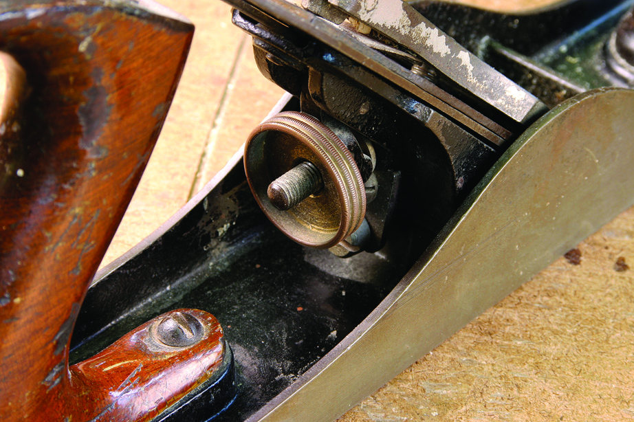
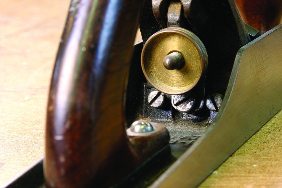
The brass wheel behind the frog regulates the depth of cut. Rotate the wheel clockwise to increase the cut and counterclockwise to decrease it.
In wooden planes a double iron, like the earlier single iron, was still secured by a wooden wedge. However, Bailey attached the cutter and chipbreaker assembly to the frog’s 45° bed with a device called a lever cap. The lever cap has a locking lever at the upper end. There is a cam on the hinged, lower end of the lever. Thus, the cap can be tightened and loosened very quickly by lifting or lowering the lever. A roundhead machine screw secures the cutter/chipbreaker assembly and lever cap tightly to the frog. Stanley and other makers found the cap’s visible front surface a nice place to display the company’s name.
The frog itself has two important adjustments – the lateral and longitudinal. When using a plane one wants the cutting edge to be parallel to the sole. If it is not, it will cut more deeply on one side than on the other and leave an unsightly track on the wood’s surface. It is important for a plane to also be able to control the chip’s thickness. On a wooden plane both blade adjustments were accomplished by tapping the tool with a light hammer. On a Bailey plane they are controlled by adjustments in the frog.
Lateral Adjustment
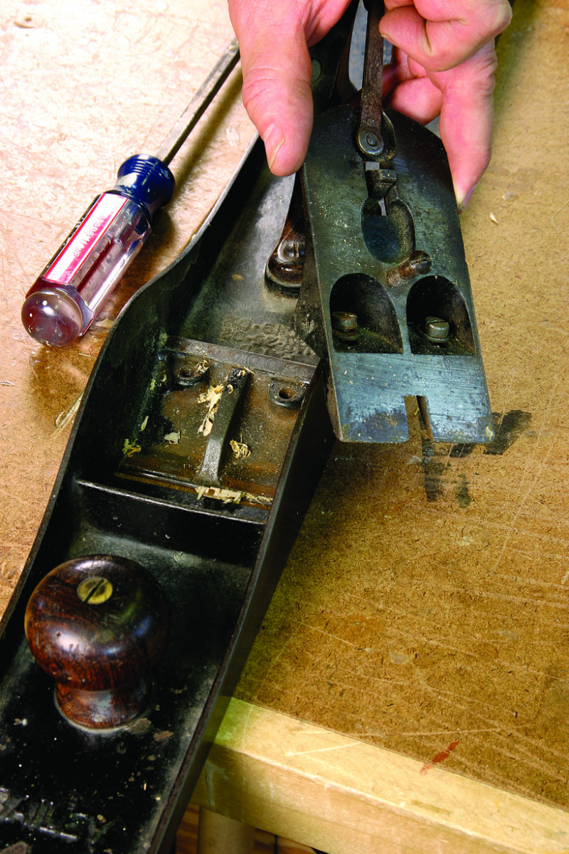
Here’s the frog assembly removed from the body of the plane. The two screws hold the frog tightly in position. The holes for the screws are slotted so the frog can slide forward and back to open and close the mouth.
Lateral adjustment, that which allows the cutting edge to be set parallel to the sole, is accomplished by a lever under the cutter. This lever extends between the cutter and the tote, to provide easy access. The lever is secured to the frog with a rivet that allows it to pivot. On the end of the lever is a wheel that fits into the slot in the cutter. On later planes the wheel was eliminated and the end of the lever became merely a bent lip. By moving the lateral adjustment lever side to side, the cutter/chipbreaker assembly will pivot under the lever cap. If you push the lever to the right, it extends the left side of the cutting edge, and vice versa.
Longitudinal Adjustment
With most Stanley planes you adjust the frog by removing the blade assembly, loosening the screws that hold the frog and then turning a screw behind the frog that will push the frog forward or back.
Behind the frog is a brass wheel (on later planes this can be made of other, less expensive materials). This wheel regulates the cutter’s longitudinal adjustments. The wheel is mounted on a stud with a left-hand thread. The yoke on the lower end of a small lever fits into a groove in the wheel. The rectangular upper end fits into a short horizontal slot in the chipbreaker. As the wheel is moved clockwise, the lever pivots and moves the cutter/chipbreaker assembly down, increasing the amount of the cutting edge projecting through the mouth. The projection is decreased by turning the wheel counterclockwise.
Open Wide – or Not
With Bed Rock planes you can adjust the frog without disassembling the tool. Loosen the two outer screws to release the frog, then turn the center screw to adjust the frog’s position. Tighten the two outer screws, adjust the iron and go to work.
The final adjustment on a Bailey-type plane is the frog itself. The width of the mouth ahead of the cutting edge affects how well the plane cuts. If the mouth is too wide it will be less effective at reducing tearing. If the mouth is very narrow, it better controls tearing. However, the plane will choke if the blade is set to take a shaving thicker than the mouth opening.
The mouth’s opening is controlled by moving the frog forward or backward, a motion that moves the cutting edge closer to the mouth’s front edge, or away from it. The frog is adjusted by removing the lever cap and cutter/chipbreaker assembly. This exposes the two screws that secure the frog to the body. On early Stanley planes, the frog was adjusted by hand after the screws had been loosened. One moved the frog to the new position and held it in the new position while retightening the screws. The process was pretty much done by feel.
In about 1914, Stanley developed a very handy device to make setting the frog more accurate. A screw with a slot in front of the head was added to the rear of the frog platform. A steel tab with a yoke in the bottom was added to the back of the frog. The yoke slid over the screw’s slot. Now, the frog retained its position when the platform screws were loosened. Rather than moving the frog by hand, one used a screwdriver to turn the slotted screw in the back of the platform. It could now be accurately moved as little as a fraction of a turn.
The best mechanism is on the Bed Rock series. It is not even necessary to remove the chipbreaker to make this adjustment. The frog is secured by two screws accessible from the back of the frog, one on either side of the frog adjustment screw. When these screws are loosened the frog can be adjusted with the whole plane intact.
Rigidity is Key
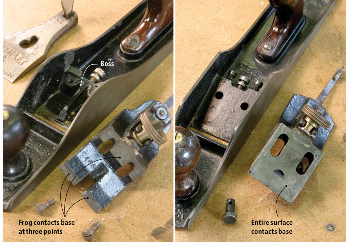
With a standard Bailey-style bench plane (left), the frog contacts the body in a few key places. With a Bed Rock plane (right), the sole and body of the plane are both machined flat for maximum contact.
Slicing a shaving by pushing a plane blade over a wood surface creates a lot of shock and stress on the cutter. The tool will only work well if all its mechanisms are rigid. The lever cap and cutter/chipbreaker assembly all contribute to this. However, if the frog moves, none of the other assemblies matter. Remove the frog from a Bailey-type plane and you will see that the mechanism sits securely on a platform created by three bosses with narrow machined surfaces. The frog’s rear edge sits on one high boss that is the width of the body. The frog’s front edge rests on two low bosses separated by a raised rib. The rib prevents the frog from moving side to side. When the frog screws are tightened, the whole mechanism is secure.
Remove the frog from a Bed Rock and you can see why these are the top-of-the line model. The frog rests on a machined bed. So instead of being in contact with a three-boss platform, the machined bottom of a Bed Rock frog mates perfectly with its platform, and is everywhere in contact. Rocking (movement due to shock and stress) is virtually eliminated.
The other two components on a Bailey-type plane not already mentioned are the rosewood tote and the front knob. Both are secured into the body with brass screws. The knob changed shape in 1922. On earlier planes it’s squat; it’s taller after this date.
The bodies of Stanley planes are protected by a shiny black surface called japanning. It is not paint, but rather asphalt based.
Function Determines Form
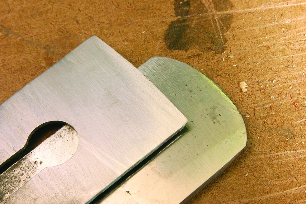
The iron of a jack plane (on top) has a gentle curve, while the iron of a scrub plane (below) has a curved cutting edge that has a pronounced arc.
A plane’s purpose determines the shape of the cutting edge. A plane blade fresh from the manufacturer is ground straight across. This is the appropriate shape for use on a wooden surface that is more narrow than the blade is wide. In other words, this is the edge you want on your jointer plane.
However, the same shape will not work on a surface that is wider than the cutter. This means that your smooth plane and a jack plane that is used on the wide face of a board cannot be ground straight. Imagine the result. The blade would leave behind a square-edged trough the shape of the cutter. This would not be at all acceptable on a visible surface. Instead, the cutting edges on a smooth plane and a jack have to be crested (as shown above). This way, they each remove a chip that is slightly thicker in the center, but that tapers out to nothing on the edges.
How much a cutting edge should be crested also depends on the plane’s purpose. A jack plane is used for heavy stock removal. For example, if you are starting with a rough-sawn board, a jack will quickly remove all the saw marks and expose fresh wood. A jack plane blade needs to be aggressive and so its cresting is pronounced.
A smooth plane is used to bring a surface close to its final stage, nearly ready for applying the finish. A surface that is handplaned will have a gentle texture that, depending on your sensibilities, you can leave or easily sand away. The appropriate amount of cresting on a smooth plane blade is almost imperceptible.
Scrub Planes v. Jack Planes
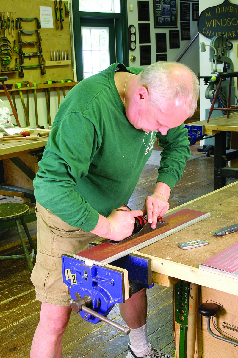
Don’t flatten a plane’s sole like you would plane wood. Instead, use equal pressure on the front knob and rear tote and move your body back and forth as you move the tool as shown above. You don’t have to flatten the entire sole. The area in front of the mouth, the toe and the heel are the critical areas.
 The crested blade on a jack plane causes many people to confuse this tool with a scrub plane. They are quite different. A scrub plane is a continental European plane designed to flatten boards. At a time in history when all the lumber that came into a woodworking shop was rough sawn and air dried, each board first had to be made flat and have the sawn surface removed. The scrub plane was the tool that started this process. Its blade has a cutting edge that is close to a semicircle. The plane is pushed quickly and forcefully across the surface of the board at a slight angle. If the board is warped or wracked, it catches the high spots and very quickly knocks them down. After the scrub plane has flattened the board, the woodworker is ready to advance to the jack plane.
In English and American shops this preparatory work was done with a jack plane. Although the cresting of a jack’s cutter is extreme relative to a smooth plane, it does not even approach that of the scrub.
Preparing for Use
Whether you have a new plane or an older one, you will want to do some steps to get it ready for use. A bit of judgment is needed to determine just how much tuning you want to do. For me, it is a function of the plane’s purpose. My jack plane is mostly used for prepping rough-sawn lumber while my best No. 604 Bed Rock smooth plane is reserved for figured wood and working around knots. Obviously, far more work has been invested in the smooth plane than in my jack. Still, my jack has not been ignored; it’s just not been pampered as much.
We have discussed the importance of the sole. Your plane will work better if the sole is flattened. You will be surprised at how irregular many plane soles are, even when the tool is brand new.
The most important place for a sole to be flat is in front of the mouth, as that is the area that holds the chip down. This is unfortunately the area that receives the most wear, and a plane that has been used a lot will frequently need work in this area.
Some people take planes to a machine shop to have their soles ground flat. I think this is extreme. Remember – a handplane is a woodworking tool and does not require precision to four decimal places. You can get the maximum performance out of your plane without it ever leaving your shop.
I flatten on a 1⁄2“-thick aluminum plate with a long strip of adhesive-backed aluminum oxide paper adhered to it. If the sole appears to be in good shape, I use #330 grit. If it obviously needs a lot of work I use a coarser and more aggressive paper, such as #120. I do not disassemble the plane, other than to remove the cutter and lever cap.
The trick is to create an even downward pressure on the sandpaper. The worst thing you can do is to use the same stroke you would use while planing. This motion will actually damage the sole. I find it best to push down on both the tote and knob with equal force. Holding that position, I slide the plane along the strip of sandpaper. To keep the pressure even, I move my body along with the plane so my shoulders stay positioned over the tool.
After several passes, you should be able to detect low spots in the sole. The newly exposed metal is lighter in color, so low spots appear as dark areas. If you have trouble detecting them, invest in a can of Dykem spray layout fluid, either red or blue. Now, the low spots will appear in bright color.
It is not necessary for the entire sole to be flat, with no low spot remaining. It is a matter of where a low spot is located, or even more precisely, where a low spot is not located. You want the area in front of the mouth flat, as well as the areas at the heel and toe. If a low spot is behind the mouth, it presents no problem.
Next, sharpen the cutter. The plane’s purpose determines the shape of the cutting edge. It also determines how sharp you want that edge. I will spend a lot more time on a smooth plane’s blade than a jack’s.
As a shaving passes up through the mouth it will find anything that it can catch on. It’s like it has a mind of its own. The chipbreaker’s edge is particularly inviting. If the shaving jams itself between the chipbreaker and the blade, work comes to a quick halt. You want to joint and hone the chipbreaker’s edge so that it makes a tight fit. I do this, too, on my aluminum plate. Slide the chipbreaker side to side on the paper with even downward pressure. Hold the rear slightly lower than the aluminum to create a sharp edge. Raising the rear will round the edge, and that is definitely not good.
When I am done, I like to put a drop of oil on all moving parts and screws.
Assembly Time
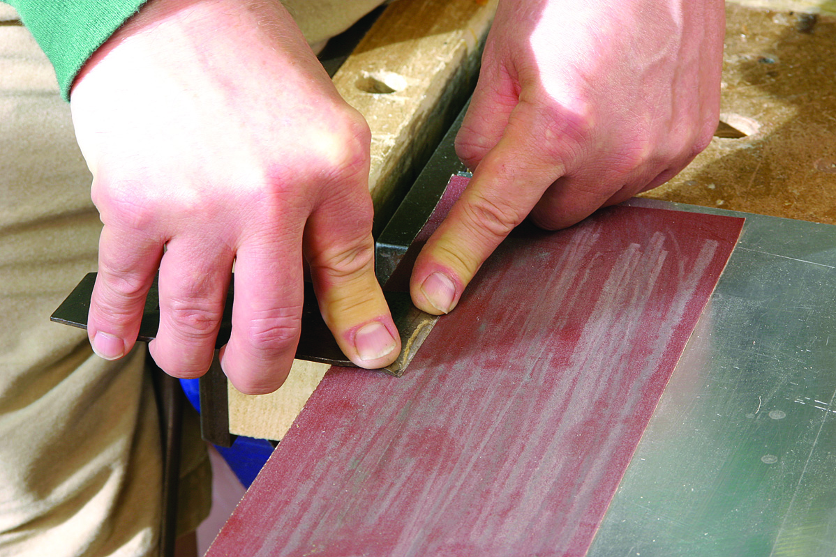
The chipbreaker must mate tightly with the back of the blade or shavings will jam in the gap. Dress the edge of the chipbreaker on sandpaper to improve the fit of these parts.
Now, assemble the plane. Avoid damaging the cutting edge when mounting the chipbreaker on the blade. Hold them at a right angle to one another while you slide the screw head through the round end of the slot. Twist the two into alignment and slide the chipbreaker’s edge into place behind the cutting edge. How close to go again depends on the plane. On a best smooth plane the distance may be as little as 1⁄16“. On a jack, 3⁄16” or even 1⁄4” may be needed to let a heavy shaving pass. Tighten the screw so the chipbreaker stiffens the blade and its front edge pulls tightly into place.
Place the cutter/chipbreaker over the lever cap screw. Be sure the lateral adjustment fits into the cutter slot and that the end of the longitudinal lever fits into its slot in the chipbreaker. Place the cap over the lever cap screw, check that all parts are aligned, then push down the cam lever.
How much force is required to lower the cam is controlled by the lever cap screw. Pushing down the lever should be a positive action and you should be able to feel it lock with an audible snap. However, if too much force is required, you risk breaking something. This rule applies to all the screws and parts in a plane. They have to be tightened enough to hold the tool together, but if the plane is cast iron, it can break.
Adjust the Plane
Use your fingertips to ensure the blade is centered in the mouth and projecting enough to make a cut. Test your setting on a scrap of wood.
The first adjustment step is to see how much the mouth is open. The appropriate amount depends on the plane. To adjust this, move the frog. Remove the cutter and loosen the frog screws. If you have an older plane, move the frog as needed by hand. If the plane has a frog adjustment screw, use it. Of course, with a Bed Rock, loosen the frog screws behind the frog and make your adjustments with the plane fully assembled.
With the mouth established, adjust the cutting edge. A lot of woodworkers do this by sighting along the sole. I find it much more accurate to use my fingertips. I hold the plane sole with my left hand (I’m right handed) and place the tips of my first two fingers on opposite sides of the cutting edge. This allows me to judge the amount of projection and to determine if one side is higher than the other. With my right hand I make what ever adjustments my fingers tell me, turning the longitudinal adjustment wheel as necessary and establishing the lateral adjustment with the lever. My fingers will get me close to the appropriate adjustment, but trying the tool on wood is the final test.
Plane Maintenance
Maintenance is similar to tuning and set up, but is something that has to be done regularly. Like sharpening, maintenance is a function of use, not time. Do it when you need to do it. These are some signs. When you hone your cutter, look for pitch build up. It tends to form behind the cutting edge and along the chipbreaker’s edge. A lot of wood dust under the cutter is another sign that the plane needs some work.
Disassemble the tool into all its parts, except for the knob and tote. You will be surprised at how much wood dust gathers under the frog. I sweep this out with a stiff brush. If there is pitch build up inside the body in the area of the mouth, I remove this with paint thinner. While at it, I usually clean the whole body, wipe it with a soft cloth, and set it aside to dry. Next, I clean the frog by submerging it in paint thinner. I brush off any residue and wipe it too. It is set aside with the body while I remove any pitch on the cutter and chipbreaker.
While the plane is apart, I hone the cutter to bring back a keen edge. Finally, I reassemble the plane and adjust it as I described above.
Buying a Plane
The result of your labor: The shaving emerges from the center of the mouth and clears the tool easily without clogging.
Between the late-19th century and the mid-20th century, Stanley and its competitors produced so many planes that a plentiful supply remains. While they are easy to find, you have to look in places other than stores and catalogs. Fortunately, there is an active trade and used tool dealers are not hard to find. Your computer’s search engine will pull up lots of them. Most are very used to dealing with Internet or phone sales. These guys are generally very knowledgeable. They provide tools for a lot of collectors who are looking for rarities, or to fill holes in their collections. So, it is important to stress that you are a woodworker and want a plane to use, not for a collection.
Most tool dealers use a universal grading system to define condition. Knowing the condition in advance will help you in your purchase. Ask the dealer to explain the system to you. These guys are usually very helpful and trustworthy. They know that a plane user seldom owns one plane, and that you will probably be back for more.
Online auction sites also offer lots of planes for sale. You are more on your own here than with a dealer. So, read the description with care. You will stumble across collector jargon such as “Type 7” and “Sweetheart.” These are of no concern for a tool user. You just want a good, serviceable plane.
Planes are common items in antique shops and flea markets. The pre-war planes made by Stanley and its competitors were consistently high quality. So, it is only important to know what not to buy. Avoid tools with missing or broken parts. I will accept minor damage to the tote. Don’t buy a plane that is excessively worn, or rusted. There are too many good ones out there to settle for anything less.
As the quality of handplanes declined after World War II and that decline accelerated after 1960, the woodworking version of Gresham’s Law kicked in and bad tools drove out good. Avoid planes made in the last several decades, as well as non-Stanley brands such as Sears Handyman. These are cheap junk
Starting in the early 2000’s some companies have started to again produce excellent quality planes. Because many that are poor quality are being sold side by side, the trick is to know what to buy. “You get what you pay for” is a pretty good rule. I advise against planes that do not have a lever cap and the other Stanley features. These are tried and true features, and other arrangements usually indicate cost cutting.
The cutter in a Stanley plane is thin. Some companies have developed high-quality replacement blades that are usually thicker and better resist chatter. I use these in my best planes that are reserved for the finest or trickiest work. The rest all have their original cutters.
There are also sources for rosewood totes and knobs. Thus, these parts can be purchased to bring an otherwise good plane back to original condition.
Here are some supplies and tools we find essential in our everyday work around the shop. We may receive a commission from sales referred by our links; however, we have carefully selected these products for their usefulness and quality.