


We may receive a commission when you use our affiliate links. However, this does not impact our recommendations.
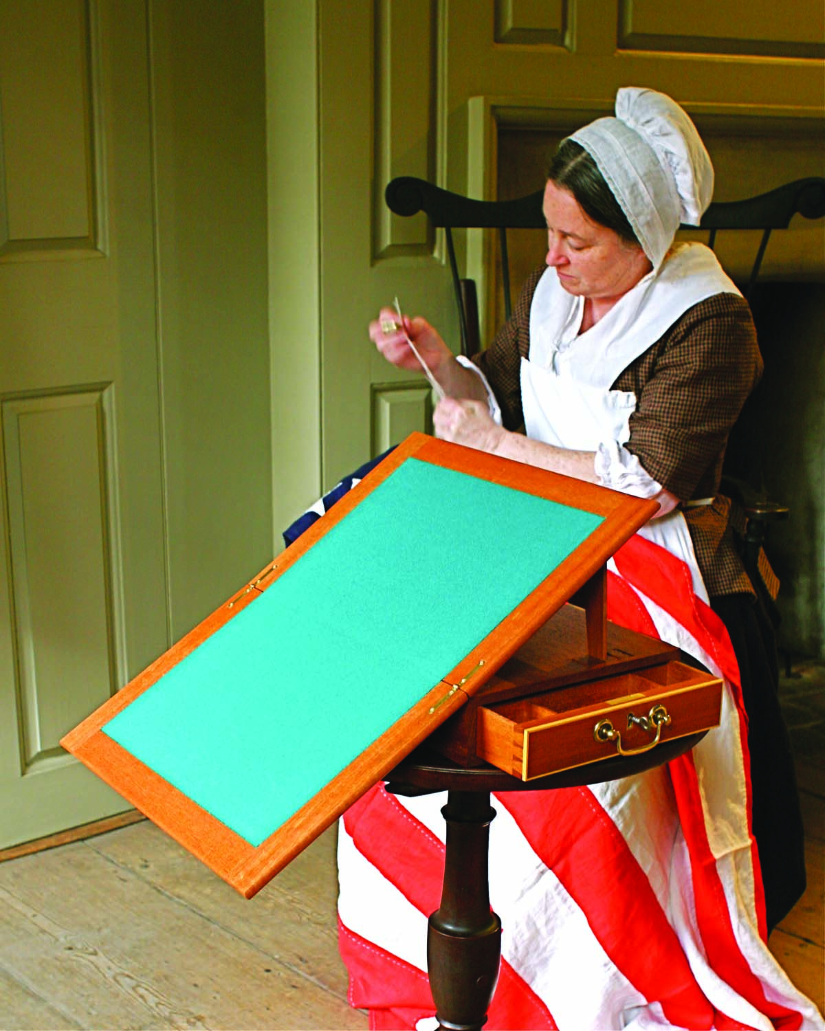
In 1776, Thomas Jefferson commissioned Benjamin Randolph, a Philadelphia cabinetmaker, to build a compact lap desk to serve as a portable office. This small mahogany box, now prominently displayed at Monticello, Jefferson’s hilltop home near Charlottesville, Virginia, has become one of the most famous wooden artifacts in American history. Jefferson wrote the Declaration of Independence on it—or so the legend goes.
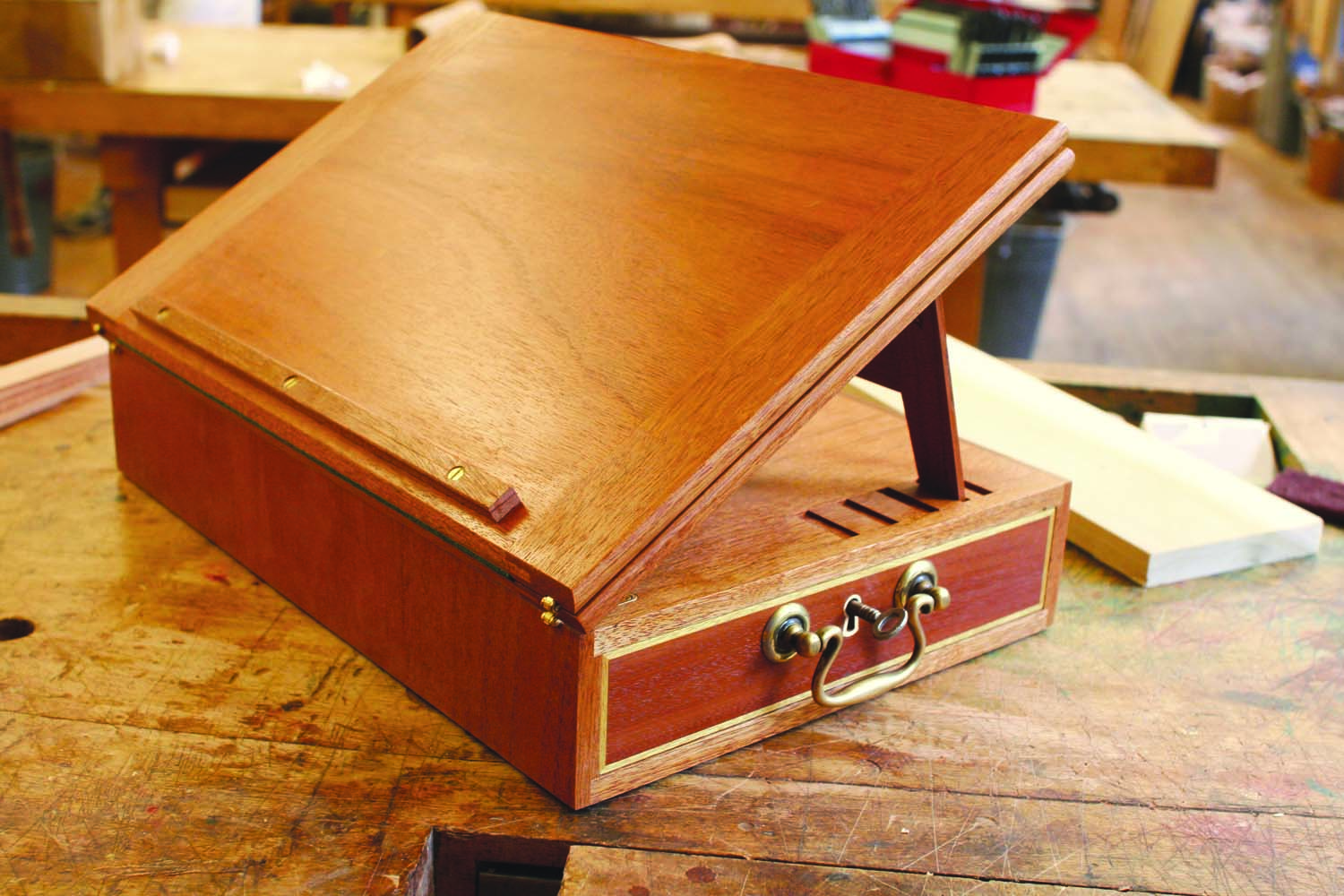
It’s an odd piece and unique among portable desks. The box is open at one end to hold a small drawer for writing paper, pens and supplies. Attached to the top of the box is a pair of hinged panels that could be set up at an angle to support a book or, when fully opened, to provide a generous writing surface. It’s also a piece with significant technical flaws—more about that later—and has been widely reproduced.
Does a portable writing desk have any practical purpose today? Probably not, but for a life-long woodworker and history buff like myself, this is an irresistible project.
Redesigning the desk
I’m sure the original desk was built to fulfill a hasty and urgent request, so the flaws are understandable. The most significant problem is that the grain of the side panels runs counter to that of the top and bottom; a condition which would cause the box to come apart or crack with changes in humidity. (Humidity levels change more drastically from summer to winter in our tight, centrally-heated houses than in the draftier homes of Jefferson’s day.) Another problem is the 5/16” thin writing panels, which are prone to warping.
Some modern builders have addressed the wood-movement problem by veneering the carcase, essentially turning its parts into plywood. While this method preserves the original appearance of the desk, veneering is a long, drawn-out process that I think is unnecessary.
Solid wood will work fine. The grain of the top, sides and bottom just has to run in the same direction, so all of these parts move in unison. There is an unusual twist in my reproduction, though: the grain runs from side to side, rather than front to back. If the grain ran the long way, the drawer opening would get smaller when the wood contracts in winter. At the very least, the drawer would stick; at the worst, the case would crack as it tried to shrink around the drawer. Running the grain the short way avoids these problems.
To further accommodate wood movement, I’ve treated the back of the desk as a floating panel. It’s outlined with stringing to look like a false drawer front and has a small reveal all the way around it, similar to the small gaps around a drawer.
To keep the writing panels rigid and flat, I increased their thickness by 1/16″ and added breadboard ends.
The diminutive scale of this desk certainly makes it a challenge to build—it’s crammed with small, difficult and precise details. I’ve played with the desk’s design, however, to make these details more manageable for an intermediate woodworker. As an instructor at the Philadelphia Furniture Workshops, I’ve been teaching students how to build my version of Jefferson’s desk. So far, each one has achieved success. You can, too.
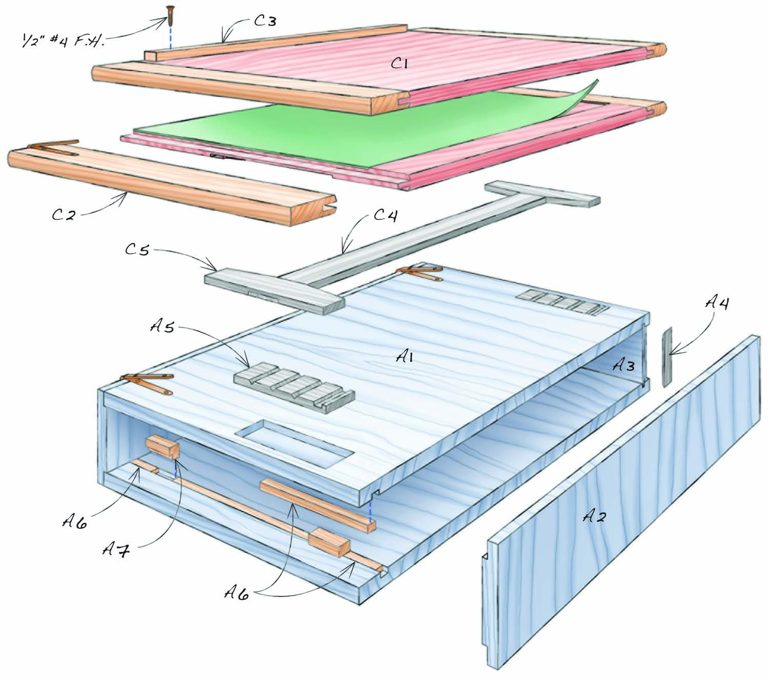
Fig. 01. Exploded View
Cut List
|
Jefferson Desk |
||||
|
Overall dimensions: 3-1/2″ H x 9-5/8″ W x 14-3/8″ D |
||||
|
Section |
Part |
Name |
Qty. |
Th x W x L (a) |
|
Carcase |
A1 |
Top and bottom |
2 |
3/8″ x 14-3/8″ x 8-7/8″ |
|
A2 |
Side |
2 |
3/8″ x 14-3/8″ x 2-1/2″ |
|
|
A3 |
Rear panel |
1 |
1/2″ x 2″ x 8-7/8″ |
|
|
A4 |
Stringing |
1/16″ x 3/8″ (b) |
||
|
A5 |
Easel support |
2 |
3/16″ x 3″ x 1″ |
|
|
A6 |
Filler |
1/4″ x 5/16″ (c) |
||
|
A7 |
Drawer stop |
2 |
5/16″ x 7/16″ x 3/4″ |
|
|
Drawer |
B1 |
Front |
1 |
11/16″ x 1-3/4″ x 8-5/8″ |
|
B2 |
Back |
1 |
3/8″ x 1-5/16″ x 8-5/8″ |
|
|
B3 |
Side |
2 |
3/16″ x 1-3/4″ x 13-5/16″ |
|
|
B4 |
Bottom |
1 |
1/8″ x 13″ x 8-3/8″ |
|
|
B5 |
Stringing |
1/16″ x 3/16″ (b) |
||
|
B6 |
Partition 1 |
2 |
1/8″ x 1-1/8″ (d) |
|
|
B7 |
Partition 2 |
2 |
3/16″ x 1-1/8″ (d) |
|
|
Easel and Writing Panels |
C1 |
Writing panel |
2 |
3/8″ x 9-5/8″ x 12-7/8″ |
|
C2 |
Breadboard |
2 |
3/8″ x 1-3/8″ x 9-5/8″ |
|
|
C3 |
Cleat |
1 |
1/4″ x 1/2″ x 11-1/4″ |
|
|
C4 |
Rail |
1 |
3/16″ x 1″ x 13-1/2″ |
|
|
C5 |
Leg |
2 |
3/16″ x 1″ x 4″ |
|
|
Notes: (a) The grain in some of the pieces in this project runs in the short direction. Here, width always refers to the distance going across the grain, while length always refers to the distance going with the grain. (b) A total of 36″ is required for the rear panel and the drawer, combined. (c) A total of 24″ is required for the lock mortise and drawer stop grooves, combined. (d) Calculate length as needed for your own design. |
||||
Build the carcase
Milling the thin wood for the desk requires great care to avoid warping. Follow this three-stage process: First, rough cut the pieces oversize. Second, resaw the pieces at least 1/8″ extra-thick. Third, joint the face sides and plane to final thickness. At each stage, allow the material to “rest” a couple of days before proceeding. As a final precaution, prepare about 25% extra material.
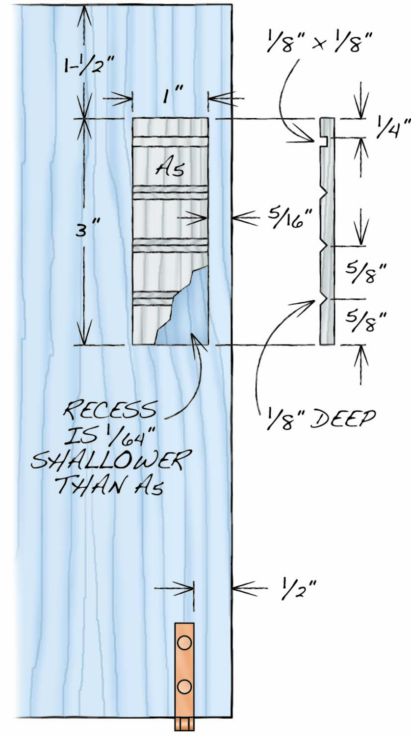
Fig. 02. Top Details
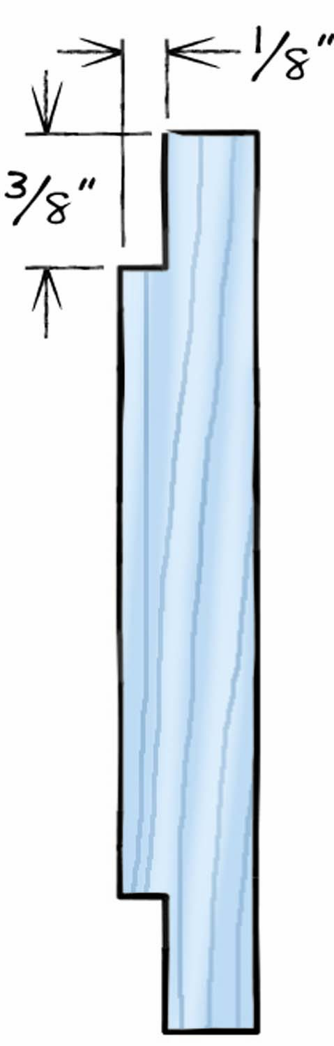
Fig. 03. End View of Side
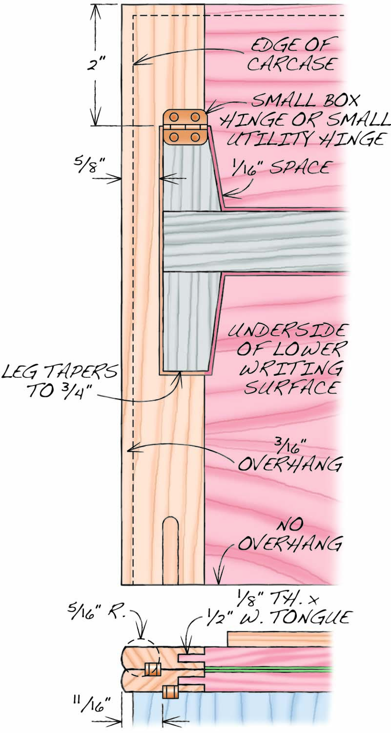
Fig. 04. Writing Panel Details
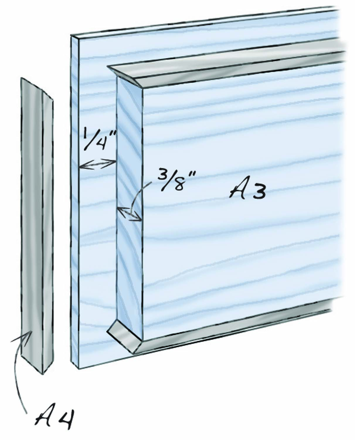
Fig. 05. Back Panel Details
Start by building the carcase. It only has five parts: the top and bottom (A1), two sides (A2) and a back panel (A3). Note carefully how the grain runs on these pieces (Fig. A) and make sure they’re flat before proceeding.
On the tablesaw, using a dado head, cut rabbets along the ends of the side panels to accept the top and bottom (Fig. 02). Into the underside of the cabinet top, along the front edge, cut a continuous groove to receive the drawer lock bolt (Fig. 03). You’ll need to purchase the drawer lock before cutting this groove. The groove should be just a little bit wider than the bolt and positioned directly above where the bolt will go.
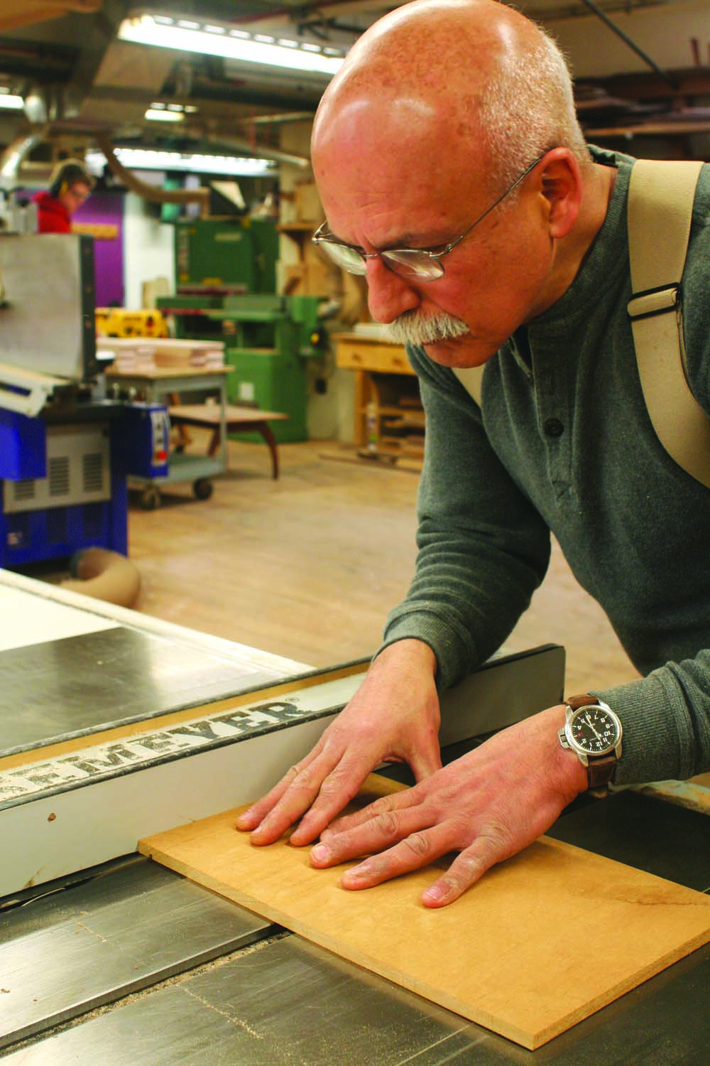
Photo 1. Start by building the desk’s carcase. Note that the grain runs the short way—from side to side. Cut grooves in the top and bottom pieces of the carcase.
Cut a 1/4” groove for the drawer stops along the front edge of the bottom piece (Photo 1). Make filler pieces (A6) and drawer stops (A7) to fit the groove. Cut the drawer stops to length, then glue in the filler pieces, leaving room between them for the drawer stops (Photo 2). Plane the filler pieces flush. Use a similar procedure for filling in the groove for the drawer lock. Note that you’ll have to figure out the exact position of the lock, side to side, before proceeding. Make the bolt’s “mortise” at least 1/8″ extra-long for insurance.
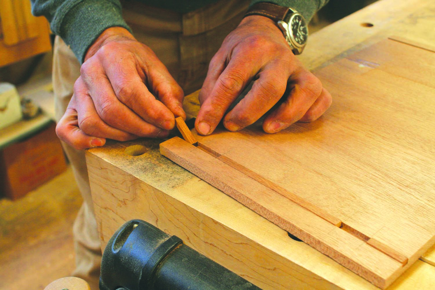
Photo 2. Glue filler pieces into one groove. The spaces between the fillers create small mortises, which will receive the drawer stops later on.
Cut a 1/8” groove along the rear edges of both sides, top and bottom to receive the back panel (Fig. 03). Rabbet the back panel to fit these grooves. In addition to the tongue, the width of the rabbet must include room for 1/16” thick satinwood stringing (A4) and a 1/16” reveal (Fig. 04).
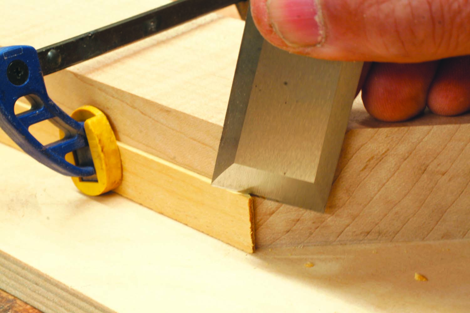
Photo 3. Pare miters on the pieces of wood that will outline the case’s back panel. The best way to avoid tearout is to use a guide block angled at 135°, not 45°.
Miter the stringing to fit the back panel (Photo 3). Plane the stringing flush with the outside face of the back panel, then make sure the panel fits inside the assembled case (Photo 4). It should be able to move about 1/16″ up and down, to allow for expansion.
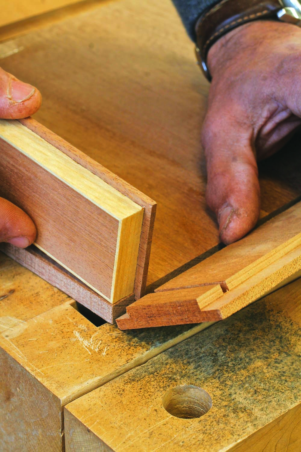
Photo 4. Fit the rear panel into grooves in the top, bottom and sides of the carcase. This piece has a reveal all the way around it, so it looks like a drawer front.
Make a temporary “drawer front” that perfectly fits the drawer opening (Photo 5). Use this piece to ensure that the carcase is square when you glue it together. After the glue is dry, plane and scrape the joints flush.
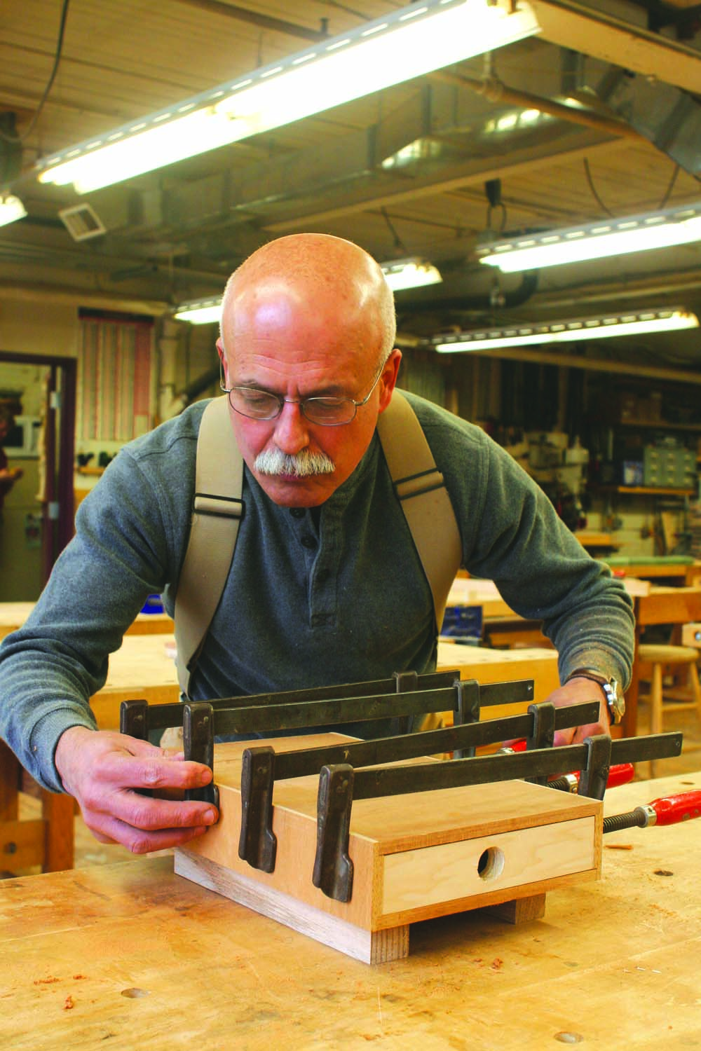
Photo 5. Glue the carcase together. To help keep the assembly square, place a tight-fitting piece of wood in the opening where the drawer will go.
Make the easel
The easel consists of two legs (C5) and a rail (C4) forming an “H”. The pieces are connected with half-lap joints (Photo 6). The original desk’s easel was made with 1/8″ stock, but I increased its thickness to 3/16″ to make it stronger and easier to build. Cut each half of the joint a little shy, then plane the corresponding piece to fit. Taper both ends of each leg, then up the easel.
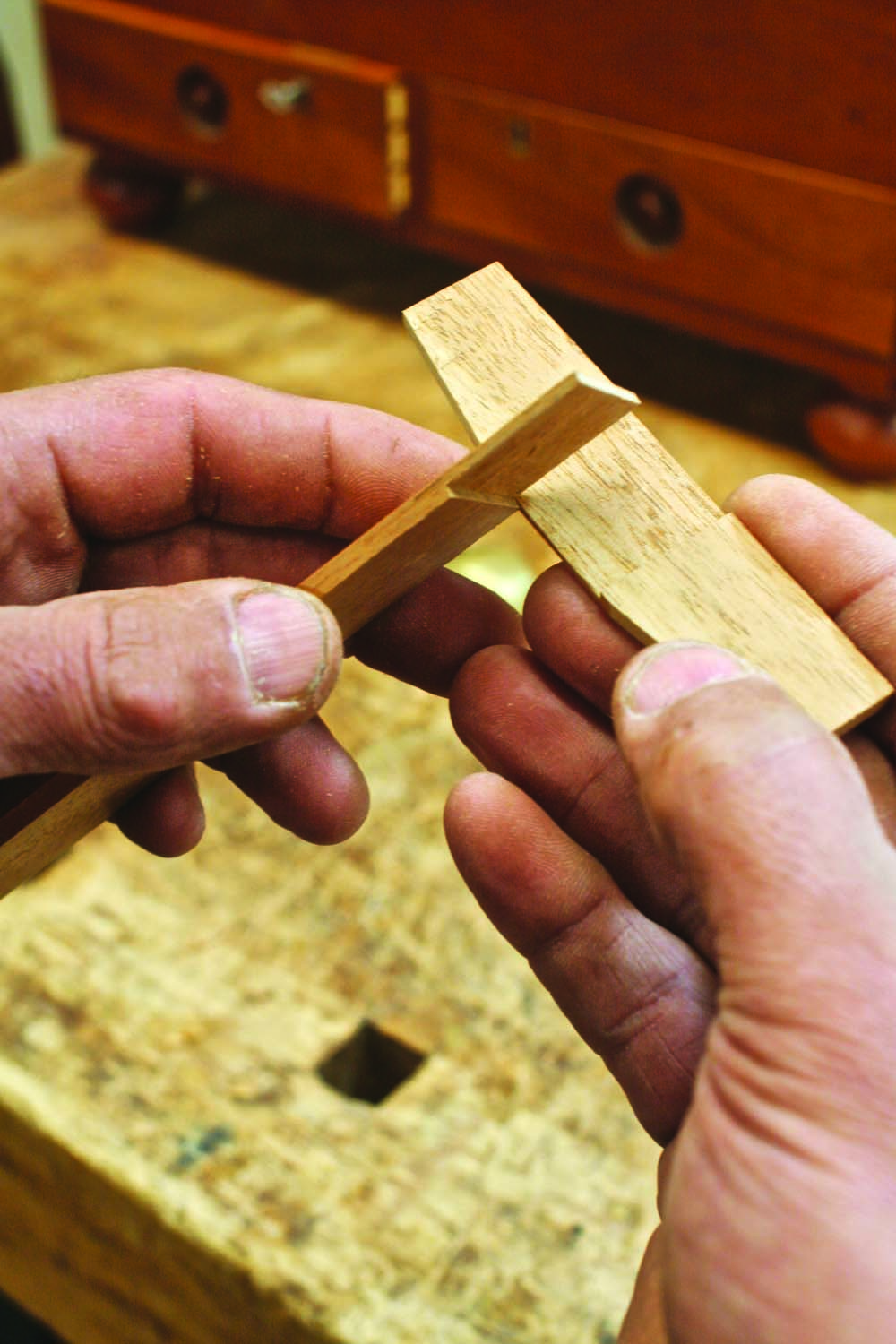
Photo 6. Make the easel. When placed in the V-grooves in the top of the carcase, the easel’s legs will support the writing panels at four different angles.
The easel will be hinged to the underside of the lower writing panel (C1). When opened, its feet are set into narrow, angled mortises in the top of the carcase, thus supporting both writing panels at an angle.
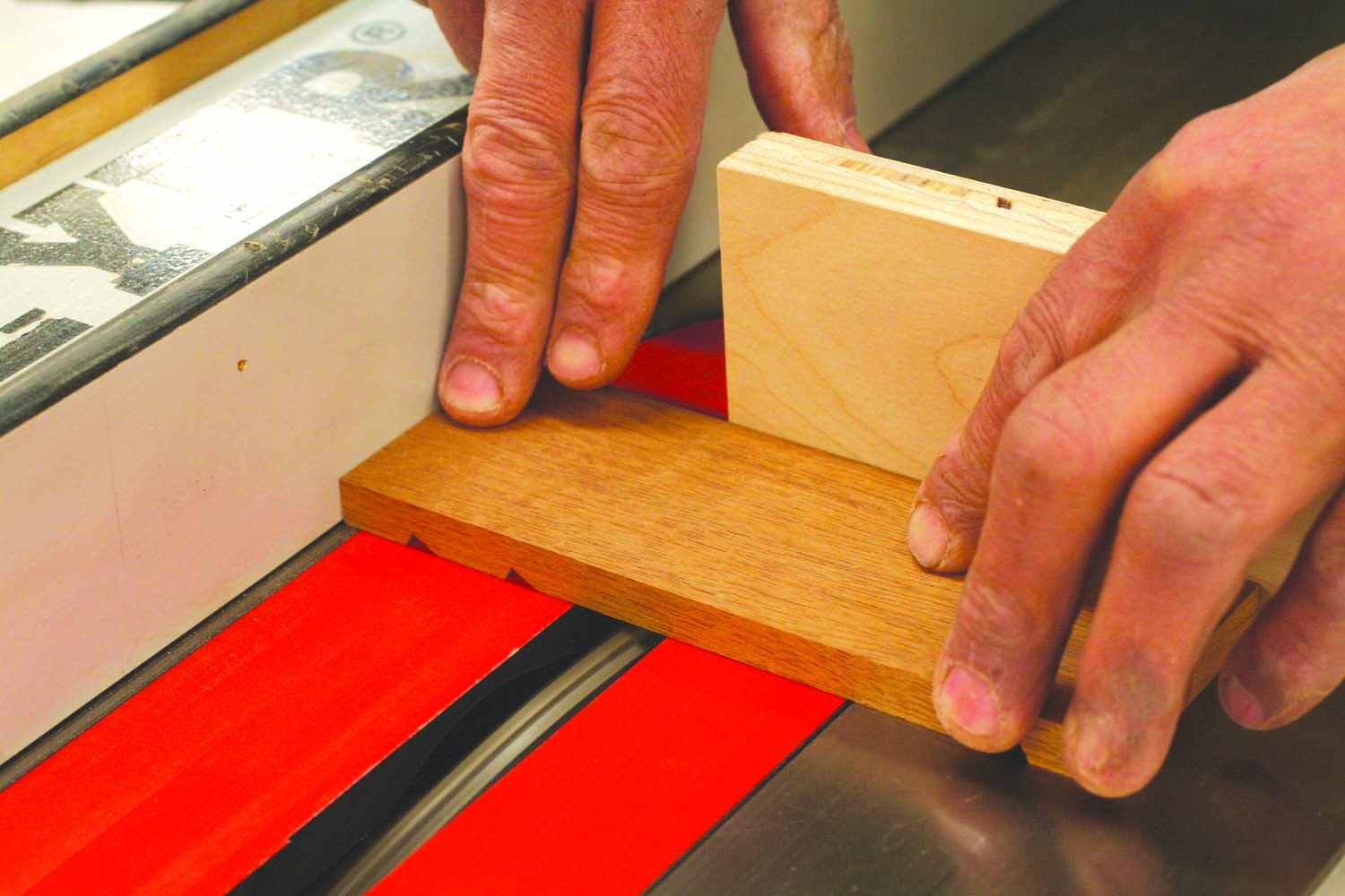
Photo 7. Saw a series of V-grooves across a thin block. These grooves will support the easel when the desk’s writing surfaces are tilted up. Rip the block in half.
Rather than tediously chop each mortise—and run the risk of ruining the top by making a mistake—it’s best to adopt a different strategy, using inlaid “easel support” pieces (A5). Make both pieces from one blank. Saw the blank (Photo 7 and Fig. 05), then rout shallow rectangles in the carcase top to receive the supports. Cut the blank into two pieces that fit the recesses (Photo 8), then glue the supports in place and plane and scrape them flush. Note that the orientation of the support’s grain is the same as the carcase’s top.
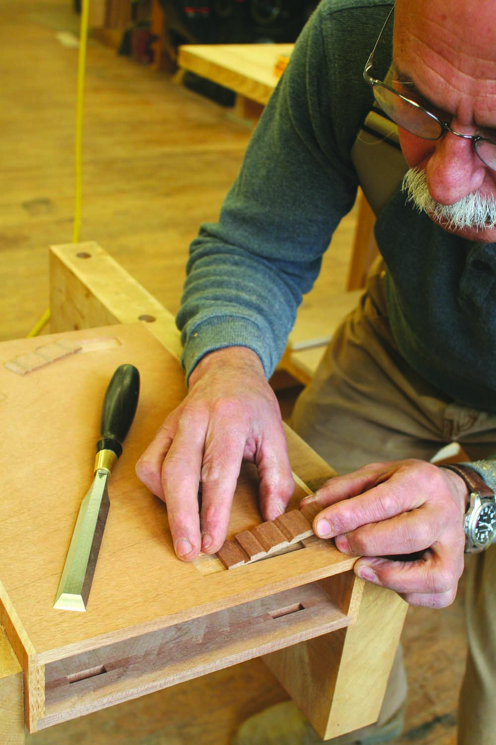
Photo 8. Fit and glue the blocks into two recesses in the top of the carcase. Sawing the grooves in these loose pieces is less risky than chopping directly into the carcase.
Build the writing panels
Make sure the stock for the writing panels and breadboard ends (C2) is perfectly flat before proceeding. Saw an 1/8” wide groove down the edge of the breadboards (Fig. 08), then mill corresponding tongues on the ends of the panels. Leave the tongues a bit fat, then plane them down for a perfect fit (Photo 9). Glue the breadboards onto the panels. Leave 2-1/2” at the ends unglued in order to allow the panels to move with changes in humidity. Plane the breadboards level with the panels.
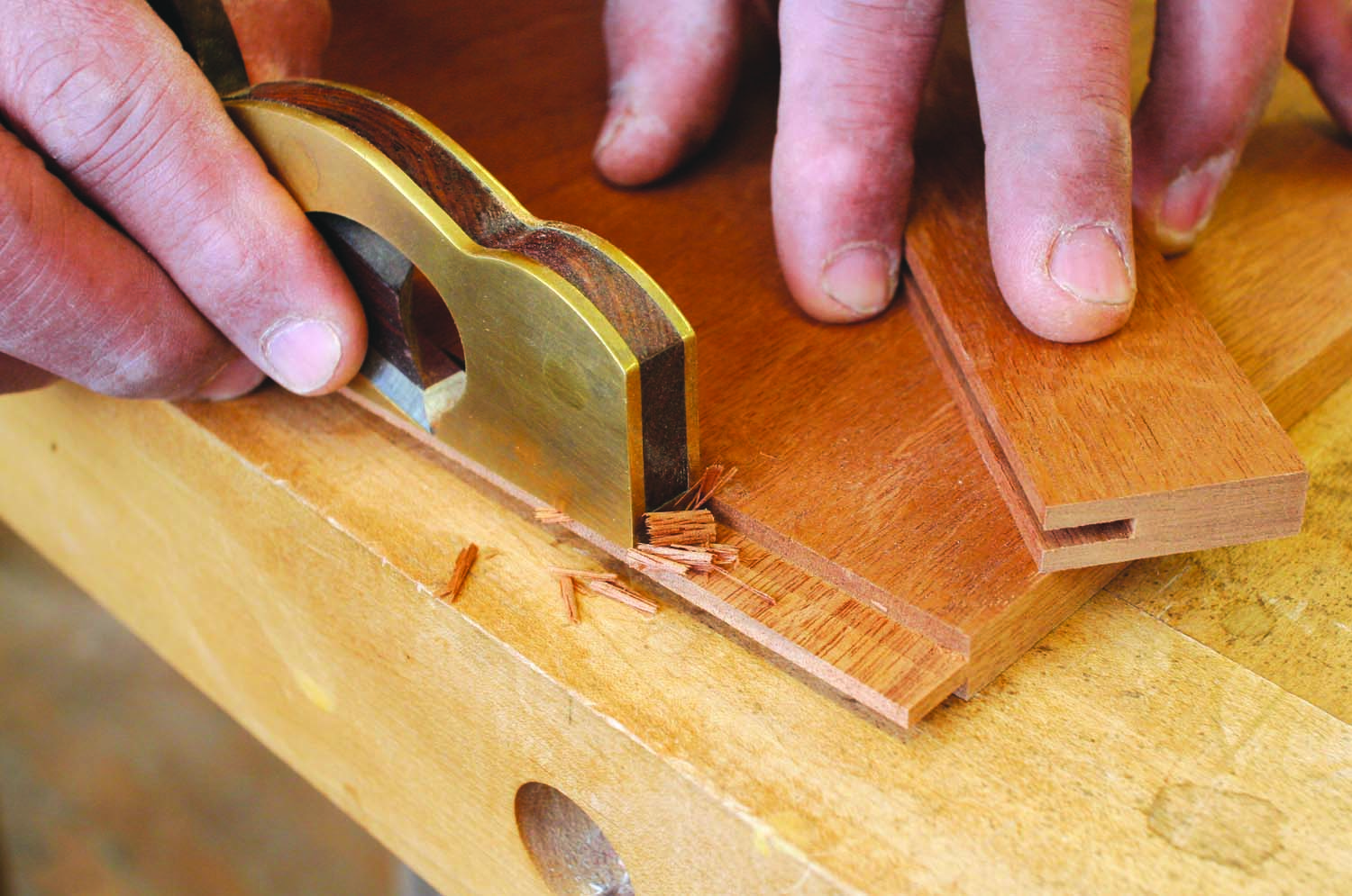
Photo 9. Make the writing panels, which have breadboard ends. Saw tongues on the ends of the panels, then plane the tongues to fit the breadboards’ grooves.
Rout or plane a thumbnail profile on three sides of each panel (Fig. 08). The side that will receive the hinges should be left square. A thumbnail shape softens the overhanging edges of the writing panels and lessens unsightly wear.
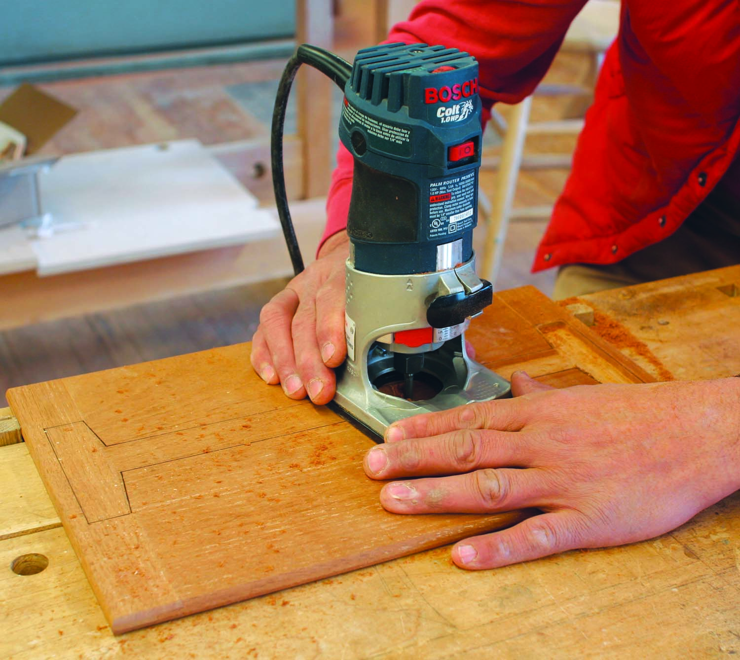
Photo 10. Rout a recess into the underside of the lower writing panel to receive the easel. Recessing the easel allows the writing panels to sit flat on the carcase.
The easel must be recessed into the underside of the lower writing panel so both panels can sit flat on the carcase. Trace an outline of the easel on the lower panel allowing a 1/16” margin all around (Fig. 08). Using a trim router with a 1/4” straight bit, excavate the panel within 1/16″ of the outline (Photo 10). Straighten the edges of the recess with a chisel. Attach the easel with two hinges.
Add the baize
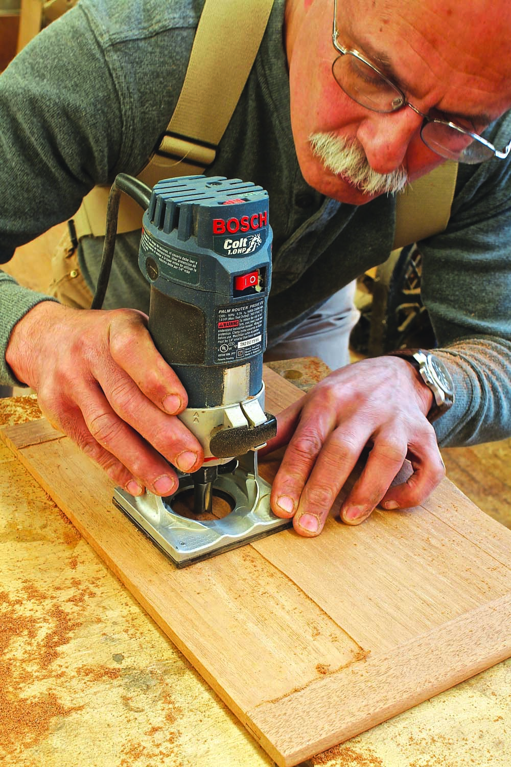
Photo 11. Recess both of the panels to receive pieces of felt. The recess is very shallow—it will enable the felt to be flush with the breadboards.
Using the trim router again, excavate the panels for the baize writing surface (Photo 11). Of course, you’ll need to buy the baize first (see Sources). Measure its thickness in order to figure out how deep the recess should be. Note that the baize doesn’t run the full width and length of the writing panels—when the panels are open, the baize is bordered by the breadboards and an uncut section of the writing panels. Draw a border on both writing panels, making sure you’ve identified the correct sides!
Beginning on the side where the hinges will eventually go, take small, light cuts, traveling lengthwise. Stop shy of the breadboards and the writing-panel borders. Clean up the edges of the recesses with a chisel and small shoulder plane.
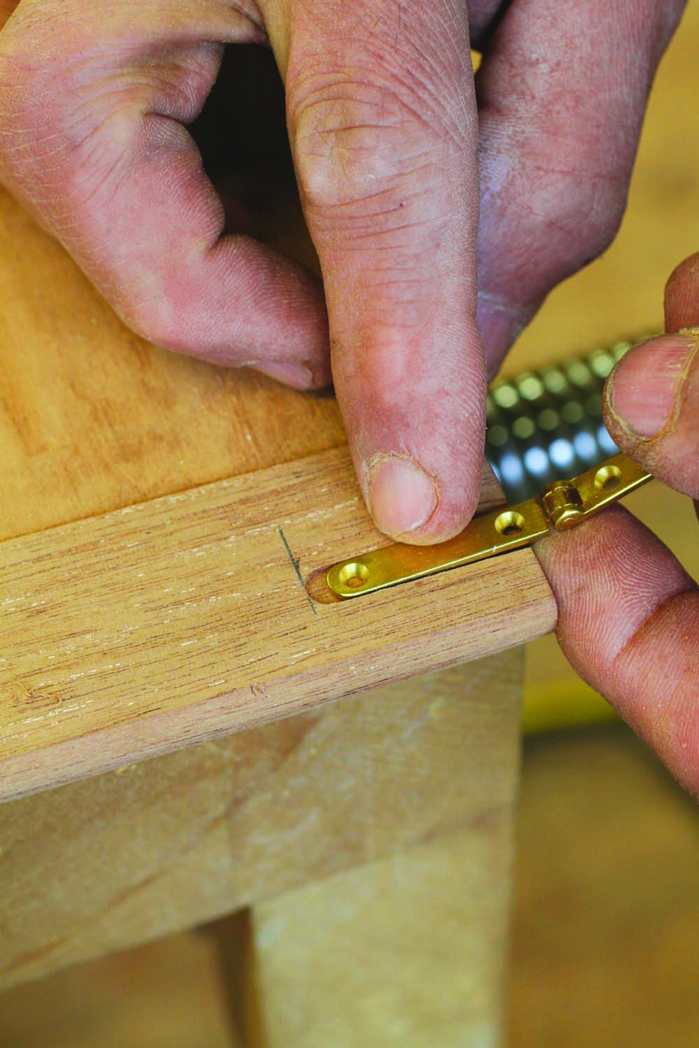
Photo 12. Rout mortises for the hinges that will connect the writing panels. Install the hinges in both panels, joining the panels together.
To join the panels on the original desk, Randolph used small butt hinges and staggered their placement because the panels were so thin. But by doing so, one set of hinges intruded onto the writing surface. Instead of small butt hinges to connect the panels, I substituted slender strap hinges. These are placed entirely on the breadboard ends and offset from each other for maximum strength. Use a router with a fence to create the hinge mortises, then install the hinges that join the two panels (Photo 12). Use a block plane and scraper to level the panels where they meet (Photo 13).
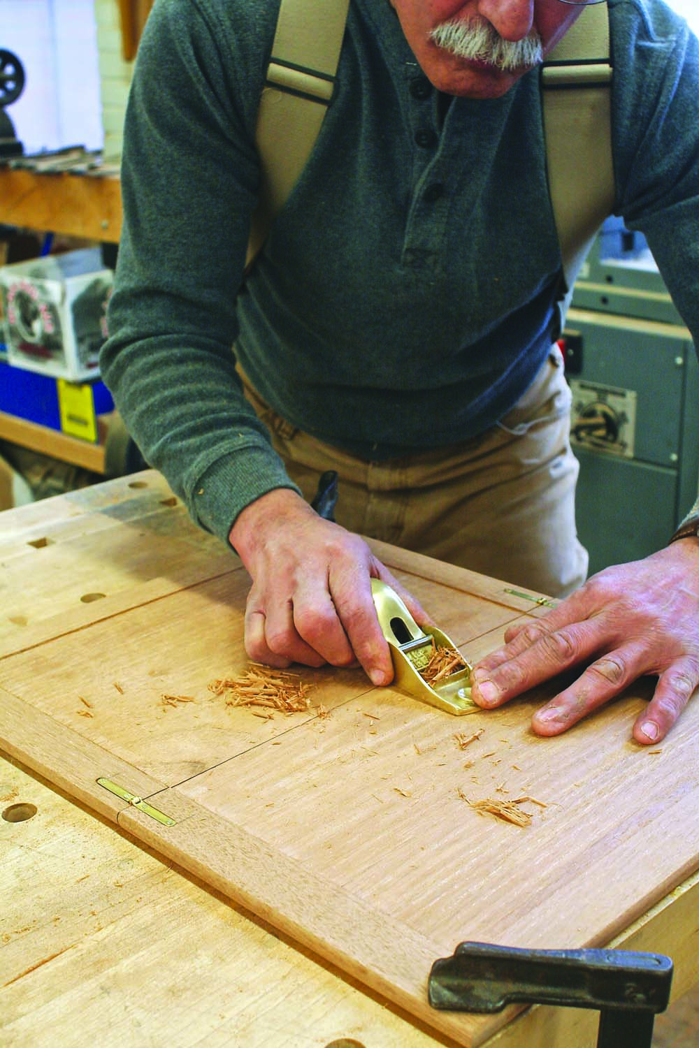
Photo 13. Plane the surfaces of the writing panels so they’re even with each other. When the panels are opened, you’ll want them to form a continuous, smooth surface.
To apply the baize, mask the borders with painter’s tape and spray a coat of 3M Super 77 adhesive onto the recessed areas. While waiting for the glue to set, cut a slightly oversized piece of baize, spray a light coat of adhesive onto its back and set it aside. After a few minutes, replace the painter’s tape (sullied by adhesive overspray) with a fresh layer.
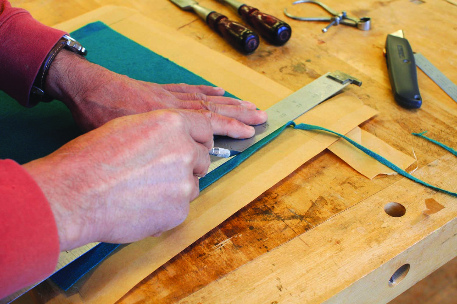
Photo 14. Glue oversize pieces of felt into both recesses, then trim the felt to fit before the glue dries. Edging tape protects the wood.
Carefully drape the baize over the panels, gently press the fabric into place and smooth out any wrinkles. Lightly push the material into each corner. Carefully trim the baize in place with a sharp X-Acto knife (Photo 14). With the baize only lightly glued down, you should be able to press it tightly against the frame to close up any small gaps. When everything looks good, slide a flat block over the baize, pressing down with some force to ensure a good, strong bond.
Making the Drawer
Now I had come to a tricky point in the build that had to be performed carefully. This was a small desk, so the drawer parts and joinery were scaled to the (size of the) piece. That meant working with extremely thin material and precisely executing tiny joints.
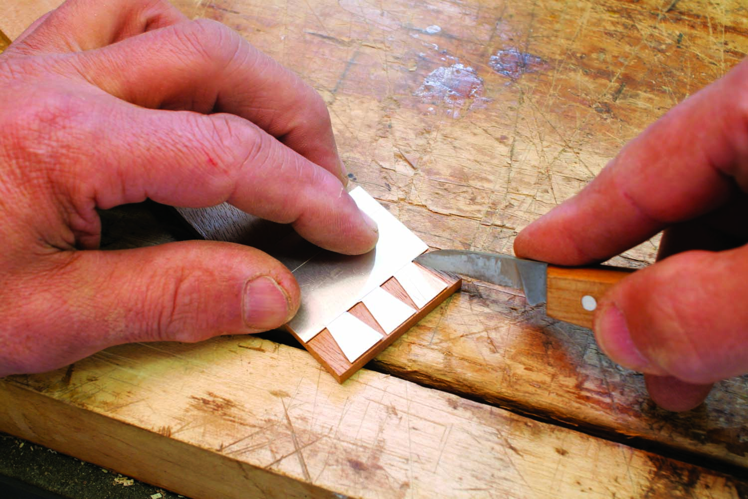
Photo 15. Make the drawer. Start by laying out the dovetails using a metal template.
Typically when beginning any new project, I perform 2 practice joints using the same wood(s), milled to the same thickness, and cut to the same size as the final project. This provides an opportunity to carefully select my tools, become familiar with the joinery, figure out the sequence of operations, and get used to the material; see how one wood yields to the other. The time spent practicing my tiny dovetails definitely paid off (Photo 15).
I milled the drawer front to 11/16”, the sides to 3/16” and the drawer back to 3/8” (I’ll explain later), then cut the drawer sides and front to final dimension; making a special effort to cut the drawer front to a very tight fit.
The Drawer Dovetails
The drawer is joined with half-blind dovetails at the front and through dovetails at the back, which is typical of a well-made period drawer. The half-blind dovetails are the one that will show. They’re the one subject to the closest scrutiny. So, take your time, do a nice job.
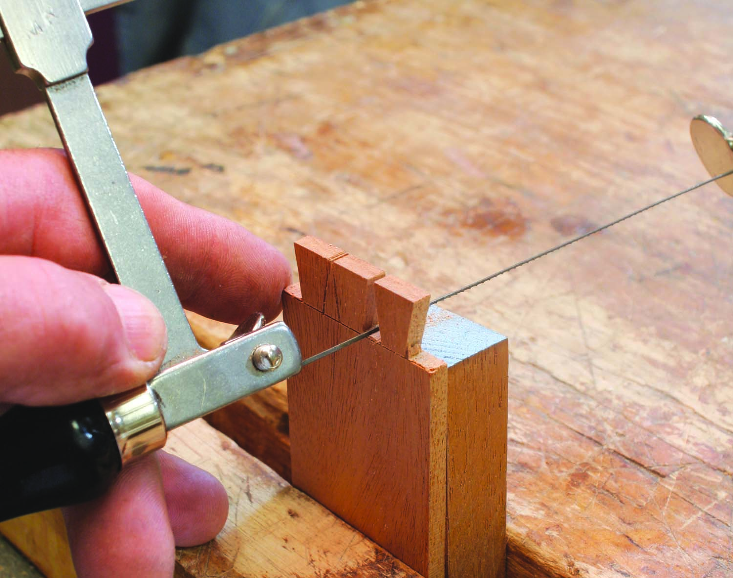
Photo 16. Cut out the waste pieces between the tails using a jeweler’s saw. These openings are very small!
To better accommodate the drawer lock, I thickened the drawer front to 11/16” (almost double the thickness on the original desk). This also allowed me to elongate the pins, producing a nicer looking, more elegant joint (Photo 16).
I laid out the 8 degree dovetails onto a piece of aluminum flashing; marked the outline of the joint into the metal with a utility knife, and cut out the waste with stationary scissors. This produced a template that could be reused, altered, or discarded. With the template, I was able to mark a single, easy-to-see, easy-to-follow dovetail outline directly onto my material.
I always do my tails first. After laying out the baseline and angle, I cut a fine, clean kerf directly through the line. With a jeweler’s saw, I remove the waste near the baseline, then perform very minor clean up with a small chisel and a marking knife.
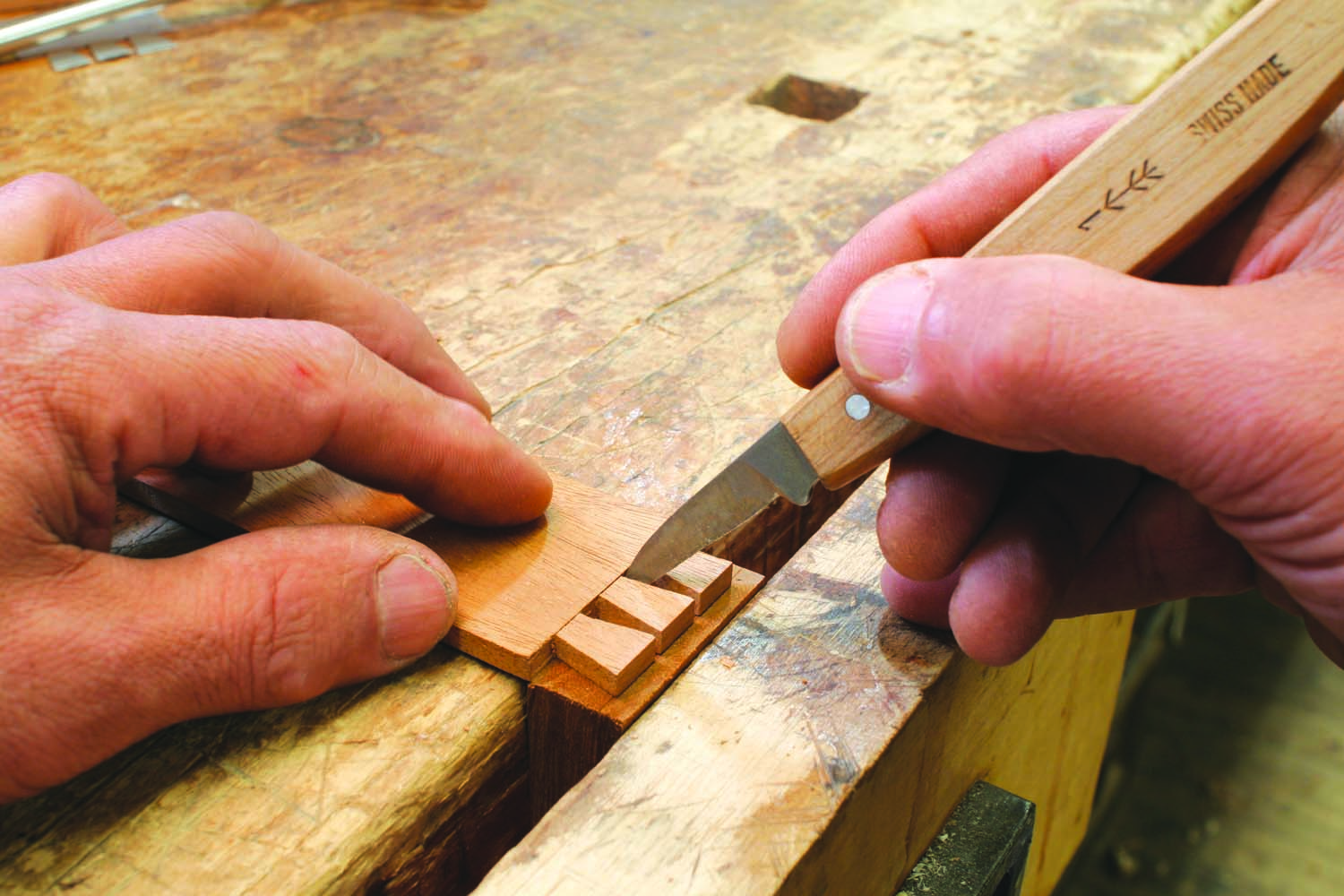
Photo 17. Trace the tails onto the drawer front using a carving knife.
I marked out my pins (on the ends of the drawer front) using the tail board and transferring the exact outline of my tails onto the pin board. On the pin board, I cut outside of my line(s), remove the waste between the pins, and carefully pare to the line. This technique, scrupulously executed, always produces impeccable dovetails (Photo 17).
After testing the fit of the half-blind dovetails, I cut the through-dovetails at the back of the drawer using similar techniques.
The back of the drawer is 3/8” thick; substantially thicker than the sides. Since I secured the drawer bottom to the back with a small pan-head screw, the extra thick back better received the screw without splitting. If the drawer back were 3/16” (like the drawer sides) it would likely split.
After assembling the drawer parts, cut a 1/8” groove along the inside of the sides and drawer front. Be careful to “bury” this drawer bottom groove behind a dovetail. But position the groove high enough that the drawer bottom will clear the drawer stops when the drawer is inserted into the cabinet.
Setting the Drawer Lock and Key Escutcheon
Clamp the drawer front onto the bench and mark out the position of the lock. After cutting the mortise, gently press the pin (which receives the hollow end of the key) into the mortise, leaving a clear mark through which a 3/16” hole is drilled. I set and screwed the lock in place, turned the drawer front over to see the lock pin centered on the 3/16” hole. I centered the key escutcheon over this hole and marked its outline onto the drawer face.
With chisels, I pared away the waste until the escutcheon almost fit in. Then I coated the excavation with epoxy glue and pressed the escutcheon into place with a clamp, leaving it slightly proud (of the surface). Later I filed the metal flush with the drawer front.
Once the escutcheon is glued in, test fit the key. It should slide in easily and engage the lock. If the fit is a little tight, open the keyhole a bit with a file.
Completing the Drawer Construction
Next I cut the various grooves to receive the interior drawer partitions, which can be cut by hand or routed out to receive the 1/8” partition material. I’ve done it both ways. Whichever you choose is fine. With the partition grooves cut and the partitions set, I glued up the drawer.
The drawer bottom was made of 1/8” material (with the grain running side-to-side), let directly into a shallow groove on the drawer front and sides. The front edge is glued into the drawer front and the back edge is held in place with a small screw. This allows the bottom to move across the grain; directing the cross-grain movement to the back of the cabinet, where it won’t interfere with the operation of the drawer.
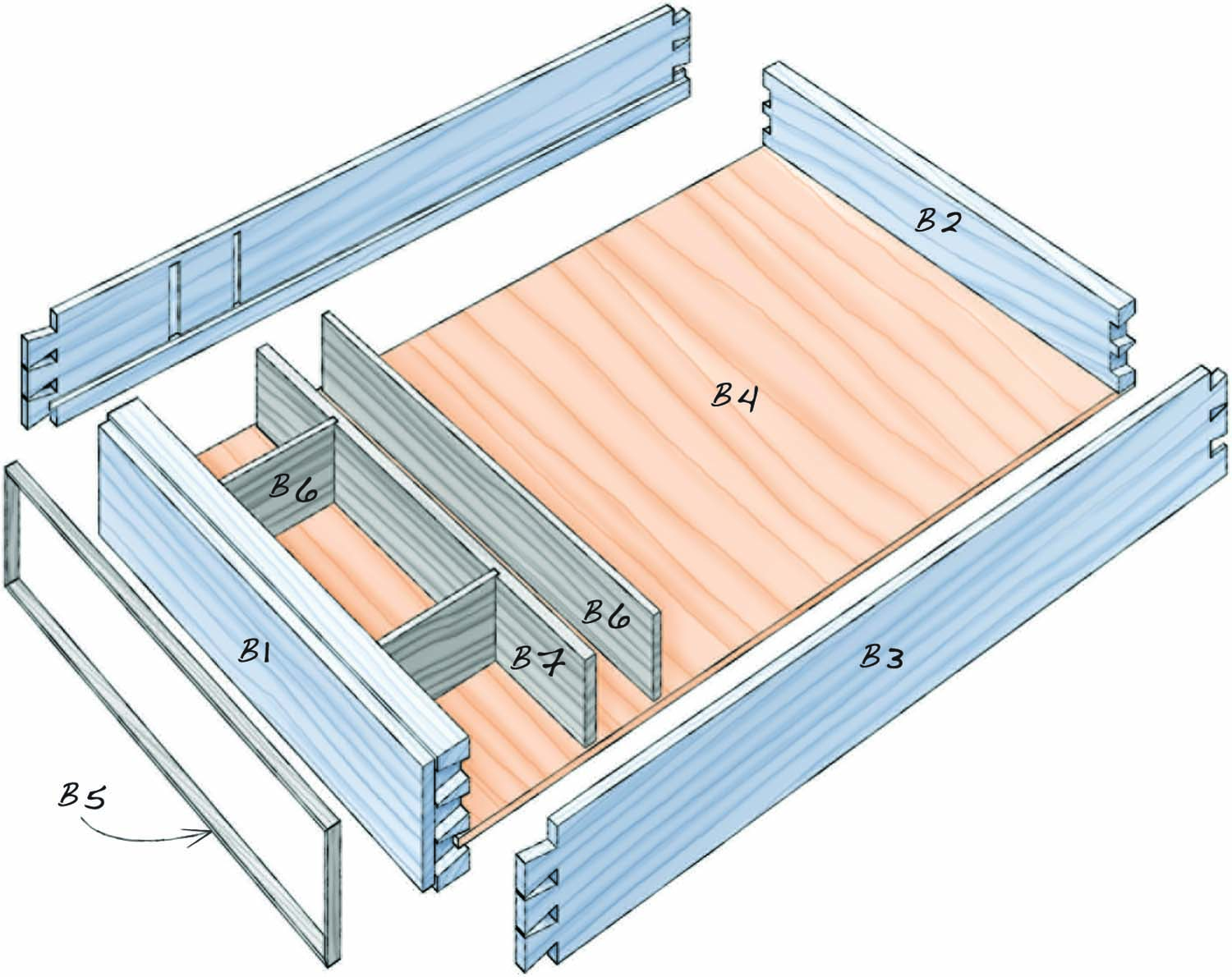
Fig. 06. Exploded View of Drawer
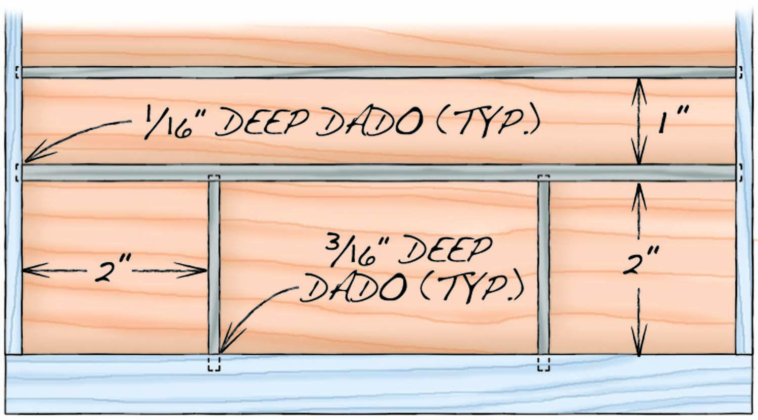
Fig. 07. Drawer Partitions
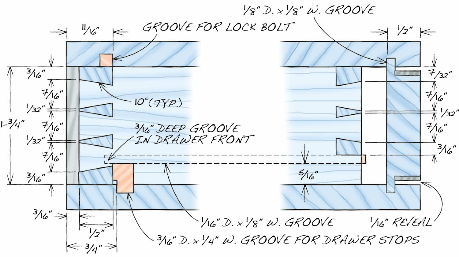
Fig. 08. Carcase and Drawer Details
The Drawer
With all the parts cut and fitted, I glued up the drawer box, inserted the partitions, and slid in the drawer bottom. When completely assembled, I checked it for square. This being such a small drawer, it came together easily without any problems.
Photo 18. Plane the joints even before gluing the drawer.
The assembled drawer was just a bit too wide to slide into place, but a few deft plane strokes took care of that. I planed and trimmed the drawer to a snug fit with just the smallest reveal all around (Photo 18).
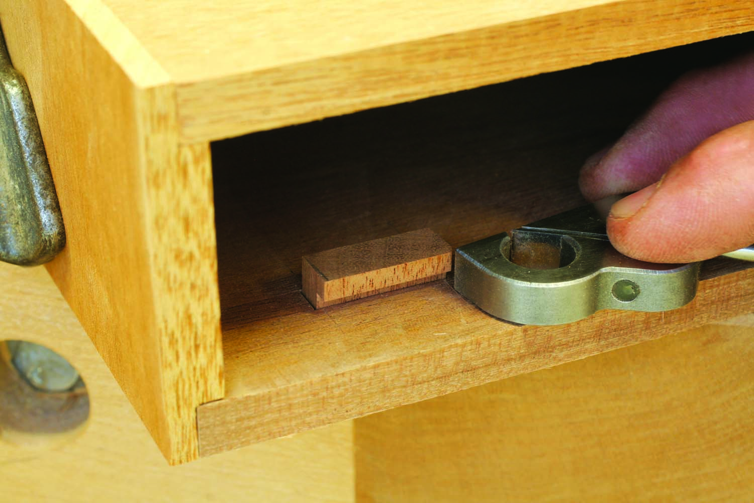
Photo 19. Install the drawer stops. Using a small bullnose rabbet plane, shave the front edges of the stops so the drawer front is flush with the carcase.
With the drawer finally fitted, I dropped the 2 drawer stops into their mortises and with a small shoulder plane, trimmed the stops until the drawer front lined up perfectly with the case and the lock bolt easily engaged the mortise, securing the drawer (Photo 19).
The Drawer Front Stringing
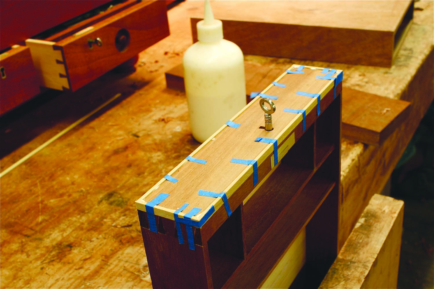
Photo 20. Glue stringing around the front of the drawer. Save for the lock and escutcheon, the back panel has the same look.
I cut a small rabbet all around the drawer front on the table saw, burying much of the blade and leaving only enough exposed to cut a 1/16” x 3/16” rabbet for the stringing. I glued the stringing into place and held it with masking tape until dry, then trimmed it flush with a block plane (Photo 20).
Assembling the Desk
The final steps were to attach the writing panel assembly to the cabinet with the slender strap hinge. Once joined to the case, the writing panels should lie flat to the case when closed then easily swing open to maintain the desired angle. The opened writing panels should provide a flat surface. If they bind when opened, bevel the hinge edge of the upper panel. This should take care of the problem.
The last piece was to install the small strip to support a book when the writing panels are raised and propped at an angle. This strip was attached with #6, ½” flat head, brass screws.
Finishing the Desk
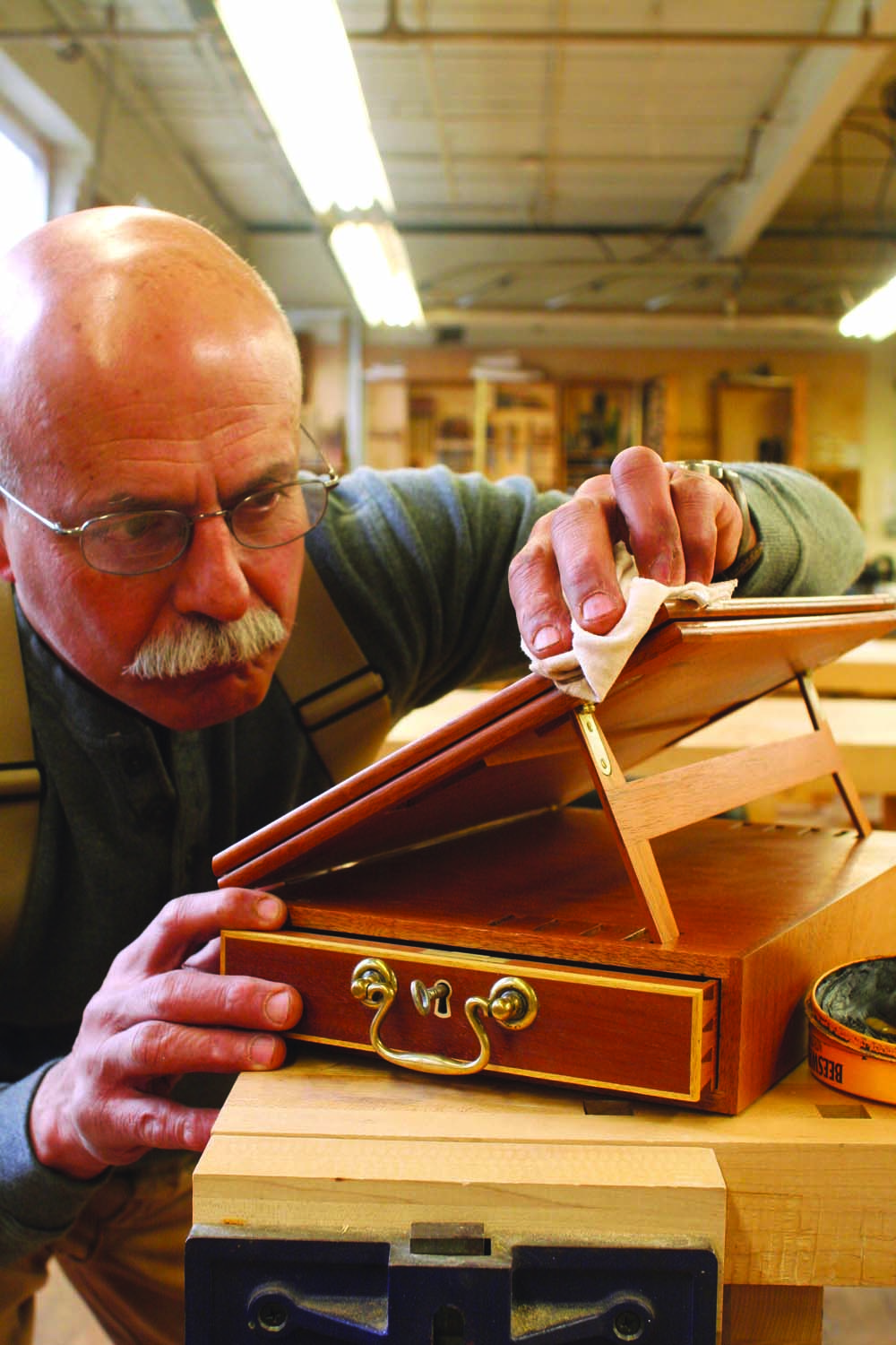
Photo 21. Finish the desk with shellac, followed by a coat of paste wax.
I dismantled the desk and after a thorough sanding, applied a sealer coat of shellac and rubbed it out when dry. This was followed by a full-strength coat (2 lb. cut). After the second coat dried, I rubbed out the desk and applied a coat of paste wax. The desk should be finished to a very soft, low-luster sheen; no high gloss here (Photo 21). It took no more than a few months of exposure to sunlight and plenty of gentle, but careful handling to develop a wonderful, bronze color and an attractive patina.
Here are some supplies and tools we find essential in our everyday work around the shop. We may receive a commission from sales referred by our links; however, we have carefully selected these products for their usefulness and quality.


Mario mentions a materials list which I do not see. The major brass suppliers don’t seem to carry baize anymore and I wonder where Mario gets his. Also, his bail and rosettes are classier than the ones currently at Horton Brasses, so I wonder where he gets them considering that Londonderry Brasses is no longer in business.