We may receive a commission when you use our affiliate links. However, this does not impact our recommendations.
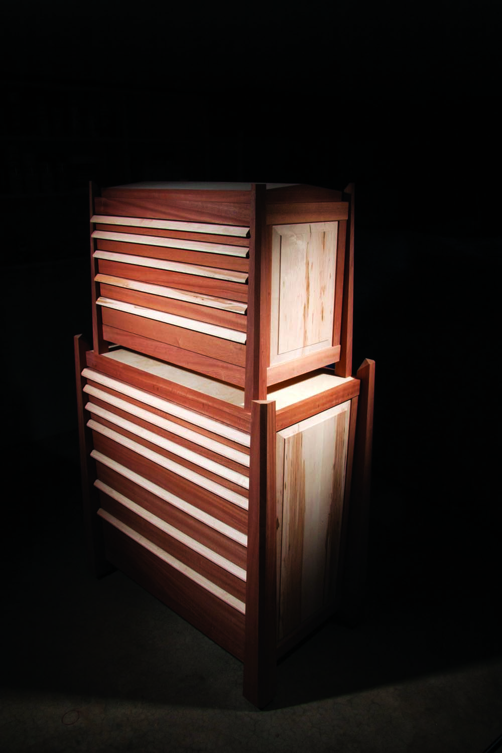
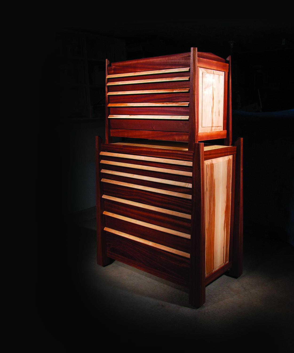
Unique because of its appearance and easy to build because it’s constructed using basic woodworking techniques, this two-part cabinet provides copious storage and signals the work—and the shop—of a true craftsman. The two cabinets share the same features and joinery, so building them simultaneously offers economy when milling the parts. But either cabinet would make a super storage unit all by itself. So, build one or both, as your shop warrants.
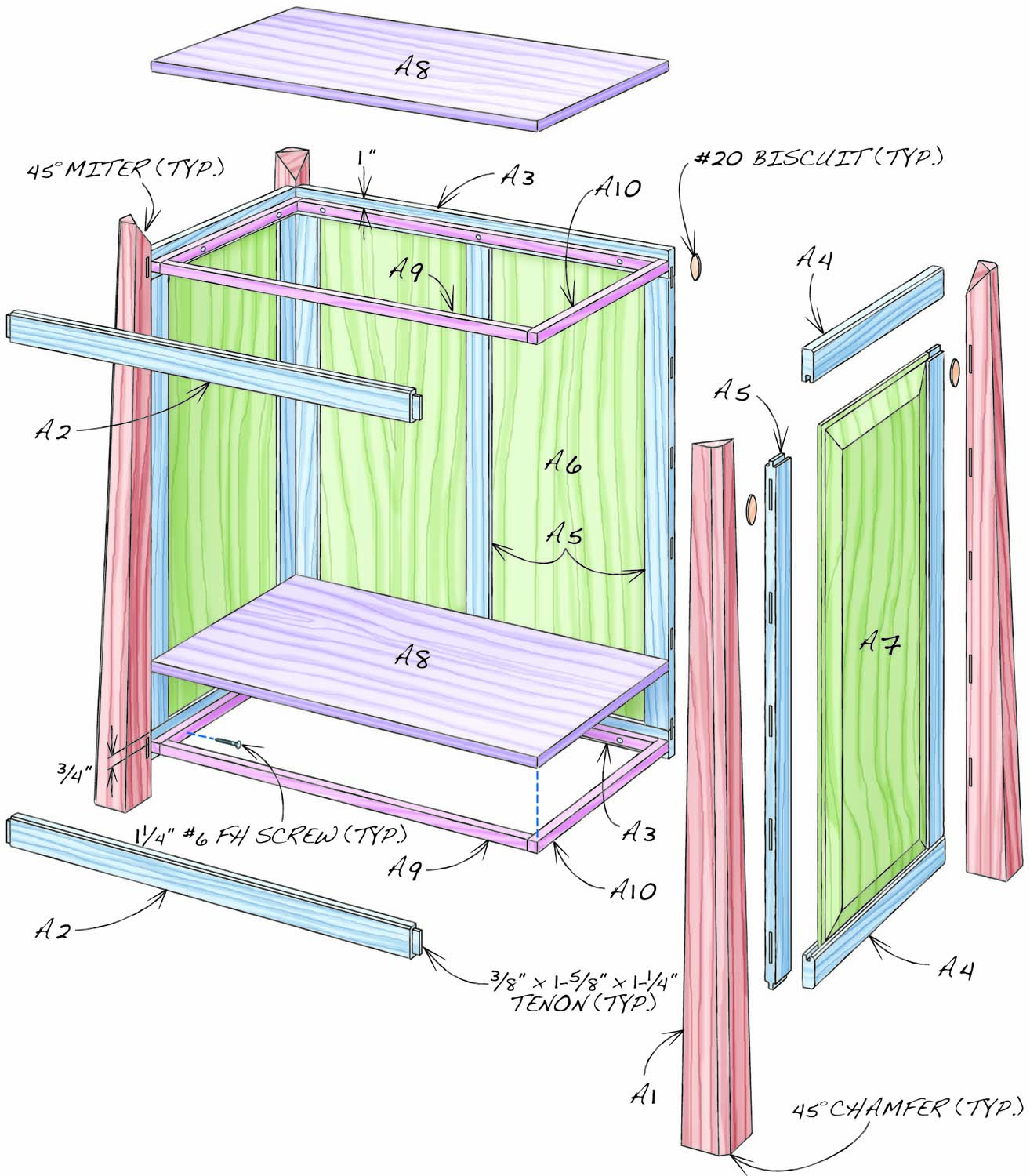
Fig. A. Base Cabinet
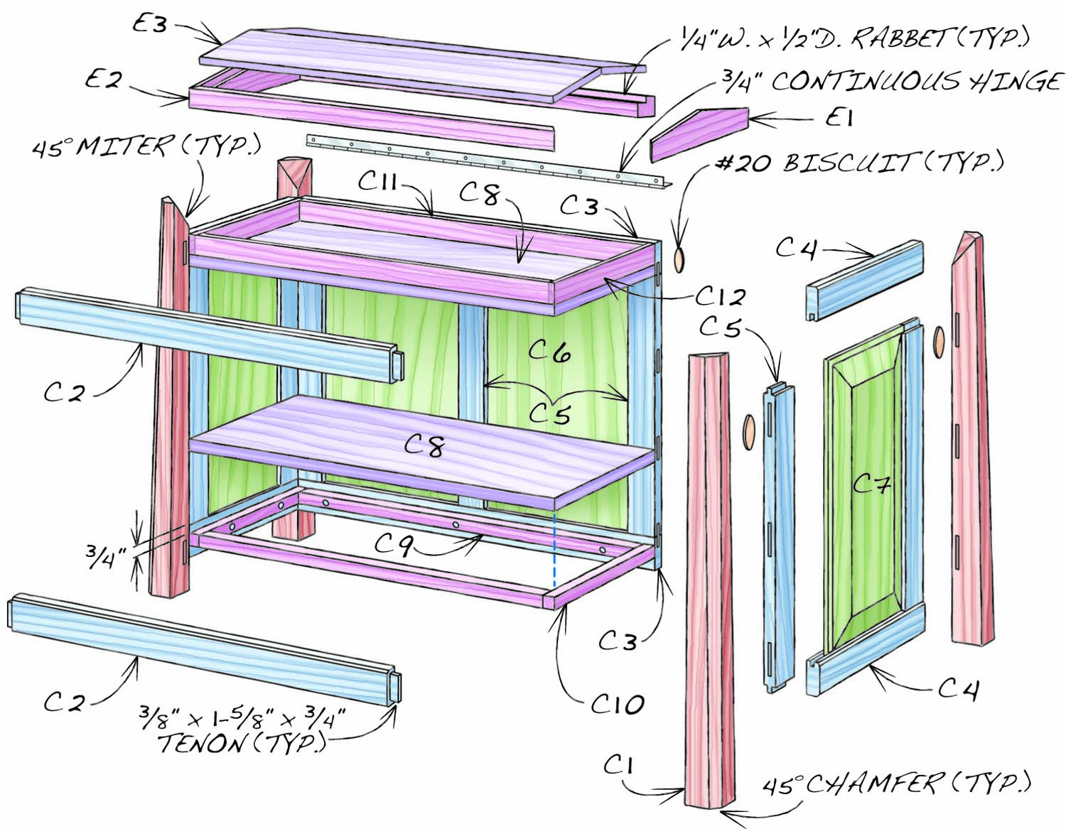
Fig. B. Top Cabinet
Cutting List
| Tool Cabinet Overall Dimensions: 58-3/4″ H x 37″ W x 24″ D |
||||||
| Part | Component | Name | Material | Qty | Th x W x L | |
| A1 | Base Cabinet | Leg | Mahogany | 4 | 3″ x 3″ x 38-3/4″ (a) | |
| A2 | Front rail | Mahogany | 2 | 3/4″ x 2″ x 33″ (b) | ||
| A3 | Back rail | Mahogany | 2 | 3/4″ x 2″ x 31″ | ||
| A4 | Side rail | Mahogany | 4 | 3/4″ x 2″ x 18″ | ||
| A5 | Stile | Mahogany | 7 | 5/8″ x 1-3/4″ x 30-3/4″ (c) | ||
| A6 | Back panel | Maple | 2 | 5/8″ x 13-3/8″ x 30-1/2″ (d) | ||
| A7 | Side panel | Maple | 2 | 5/8″ x 15″ x 30-1/2″ (d) | ||
| A8 | Top/bottom shelf | Maple | 2 | 3/4″ x 18″ x 31″ | ||
| A9 | Long cleat | Maple | 4 | 3/4″ x 3/4″ x 29-1/2″ | ||
| A10 | Short cleat | Maple | 4 | 3/4″ x 3/4″ x 18″ | ||
| B1 | Base Drawers | Box front/back 1 | Maple | 2 | 1/2″ x 1″ x 30″ | |
| B2 | Box front/back 2 | Maple | 4 | 1/2″ x 2″ x 30″ | ||
| B3 | Box front/back 3 | Maple | 6 | 1/2″ x 3″ x 30″ | ||
| B4 | Box front/back 4 | Maple | 2 | 1/2″ x 5″ x 30″ | ||
| B5 | Box side 1 | Maple | 2 | 1/2″ x 1″ x 17-5/8″ (e) | ||
| B6 | Box side 2 | Maple | 4 | 1/2″ x 2″ x 17-5/8″ (e) | ||
| B7 | Box side 3 | Maple | 6 | 1/2″ x 3″ x 17-5/8″ (e) | ||
| B8 | Box side 4 | Maple | 2 | 1/2″ x 5″ x 17-5/8″ (e) | ||
| B9 | Box bottom | Maple plywood | 7 | 1/2″ x 18″ x 30″ | ||
| B10 | Attached front 1 | Mahogany | 1 | 3/4″ x 1-3/4″ x 30-3/4″ (f) | ||
| B11 | Attached front 2 | Mahogany | 2 | 3/4″ x 2-7/8″ x 30-3/4″ (f) | ||
| B12 | Attached front 3 | Mahogany | 3 | 3/4″ x 4-3/4″ x 30-3/4″ (f) | ||
| B13 | Attached front 4 | Mahogany | 1 | 3/4″ x 7-1/4″ x 30-3/4″ (f) | ||
| B14 | Pull | Maple | 7 | 3/4″ x 3/4″ x 30-3/4″ (g) | ||
| C1 | Top Cabinet | Leg | Mahogany | 4 | 1-7/8″ x 1-7/8″ x 22-3/4″ (h) | |
| C2 | Front rail | Mahogany | 2 | 3/4″ x 2″ x 27-1/2″ (j) | ||
| C3 | Back rail | Mahogany | 2 | 3/4″ x 2″ x 26″ | ||
| C4 | Side rail | Mahogany | 4 | 3/4″ x 2″ x 12″ | ||
| C5 | Stile | Mahogany | 7 | 5/8″ x 1-1/2″ x 15-1/4″ [c] | ||
| C6 | Back panel | Maple | 2 | 5/8″ x 11-1/4″ x 15″ | ||
| C7 | Side panel | Maple | 2 | 5/8″ x 9-1/2″ x 15″ | ||
| C8 | Top/bottom shelf | Maple | 2 | 3/4″ x 12″ x 26″ | ||
| C9 | Long cleat | Maple | 2 | 3/4″ x 3/4″ x 24-1/2″ | ||
| C10 | Short cleat | Maple | 2 | 3/4″ x 3/4″ x 12″ | ||
| C11 | Long fill strip | Mahogany | 2 | 3/8″ x 1-1/4″ x 25-1/4″ | ||
| C12 | Short fill strip | Mahogany | 2 | 3/8″ x 1-1/4″ x 12″ | ||
| D1 | Top Drawers | Box front/back 5 | Maple | 4 | 1/2″ x 1″ x 25″ | |
| D2 | Box front/back 6 | Maple | 4 | 1/2″ x 2″ x 25″ | ||
| D3 | Box front/back 7 | Maple | 2 | 1/2″ x 3″ x 25″ | ||
| D4 | Box side 5 | Maple | 4 | 1/2″ x 1″ x 11-5/8″ (e) | ||
| D5 | Box side 6 | Maple | 4 | 1/2″ x 2″ x 11-5/8″ (e) | ||
| D6 | Box side 7 | Maple | 2 | 1/2″ x 3″ x 11-5/8″ (e) | ||
| D7 | Box bottom | Maple plywood | 5 | 1/2″ x 12″ x 25″ | ||
| D8 | Attached front 5 | Mahogany | 2 | 3/4″ x 1-7/8″ x 25-3/4″ (f) | ||
| D9 | Attached front 6 | Mahogany | 2 | 3/4″ x 3″ x 25-3/4″ (f) | ||
| D10 | Attached front 7 | Mahogany | 1 | 3/4″ x 4″ x 25-3/4″ (f) | ||
| D11 | Pull | Maple | 5 | 3/4″ x 3/4″ x 26″ (g) | ||
| E1 | Lid | End | Mahogany | 2 | 3/4″ x 2″ x 15-3/8″ (k) | |
| E2 | Rail | Mahogany | 2 | 3/4″ x 1-3/8″ x 25-1/2″ (l) | ||
| E3 | Panel | Maple plywood | 2 | 1/2″ x 6-7/8″ x 24-1/4″ (m) | ||
| Notes (a) Both outside faces taper to 1-3/4″ at the top; one inside face is mortised for the rail tenons. (b) Length includes 3/8″ x 1-5/8″ x 1″-long tenons on both ends. [c] Length includes 1/4″ x 3/8″-long tenons on both ends. (d) Raised center with 1/4″ tongues on all edges. (e) Length includes 5/16″-long dovetails on each end. (f) Cut oversize in width and length; trim to final dimensions when fitting to cabinet. (g) Cut from 4″-wide blank. Cut oversize in length and trim after gluing to drawer front. (h) Both outside faces taper to 1″ at the top; one inside face is mortised for the rail tenons. (j) Length includes 3/8″ x 1-5/8″ x 3/4″-long tenons on both ends. (k) Width tapers to 1-1/4″ at both ends. (l) Top edge is beveled to match the slope of the lid’s ends. (m) Both edges beveled to match the slope of the lid’s ends. |
||||||
Mill Leg Blanks
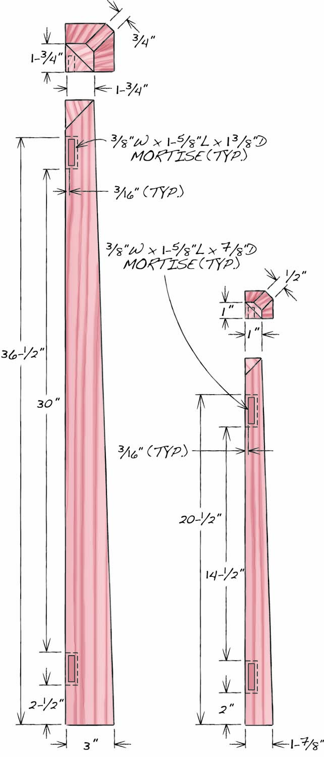
Fig. C. Legs
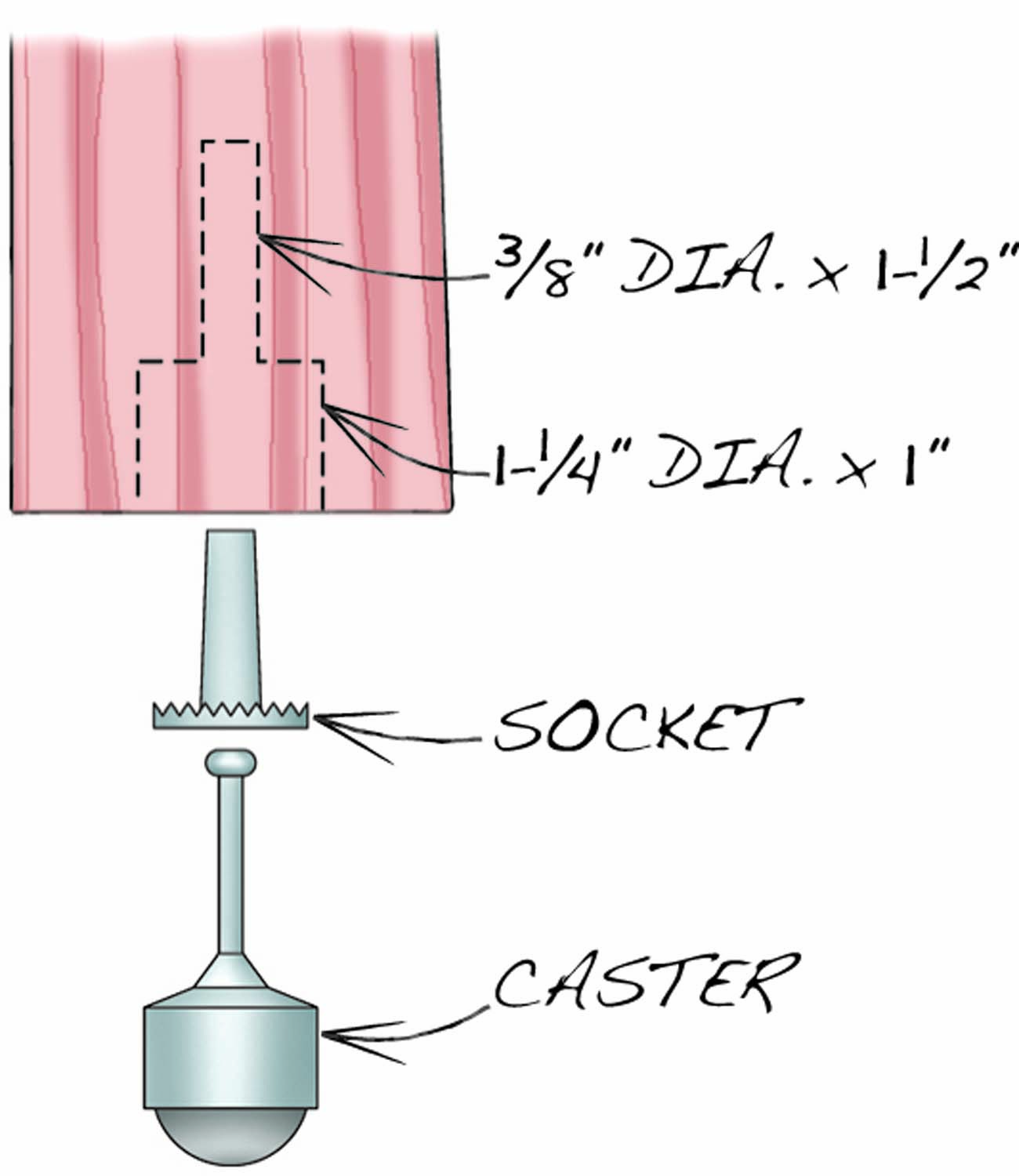
Fig. D. Base Cabinet Casters
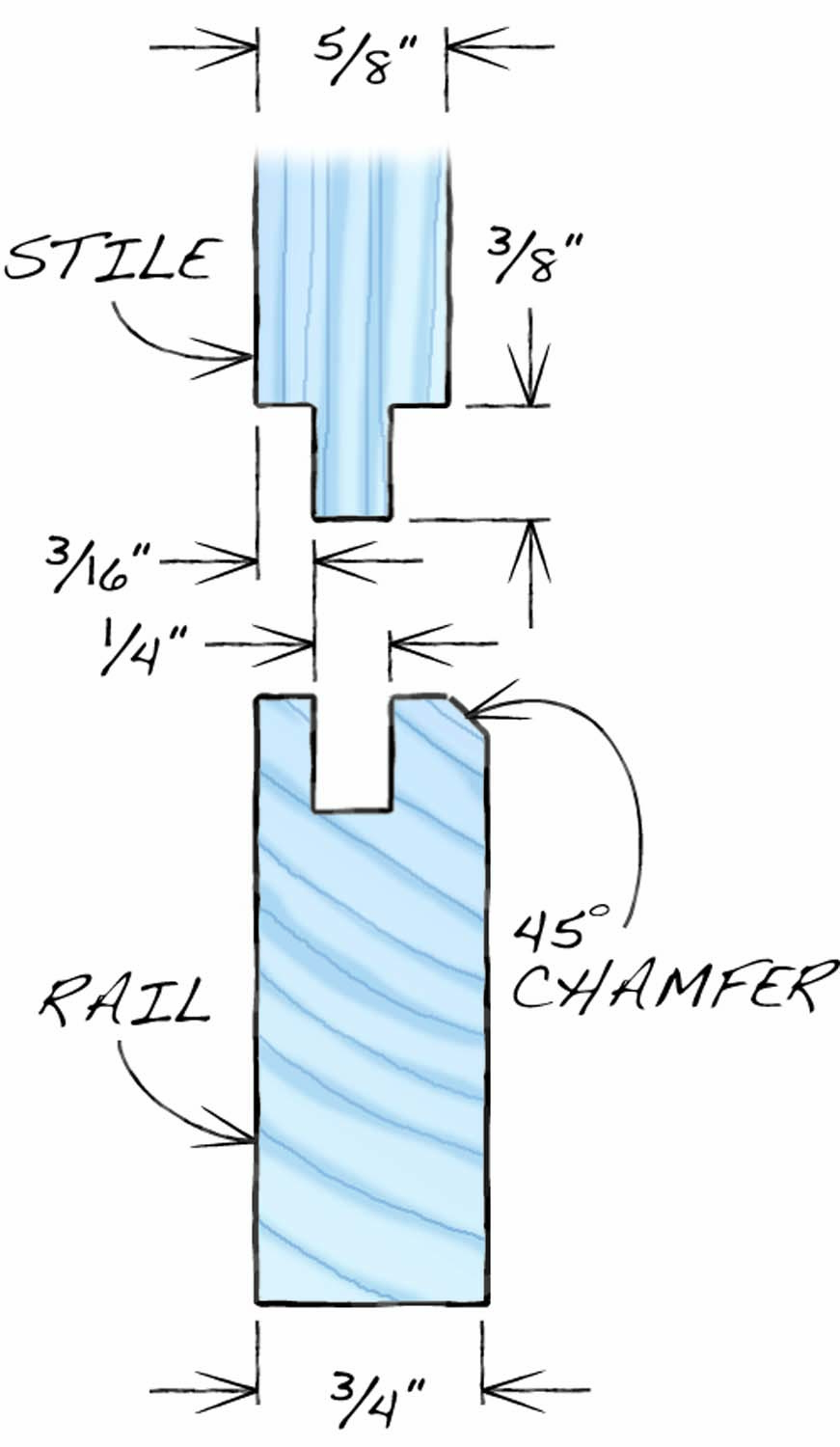
Fig. E. Panel Frame Joinery
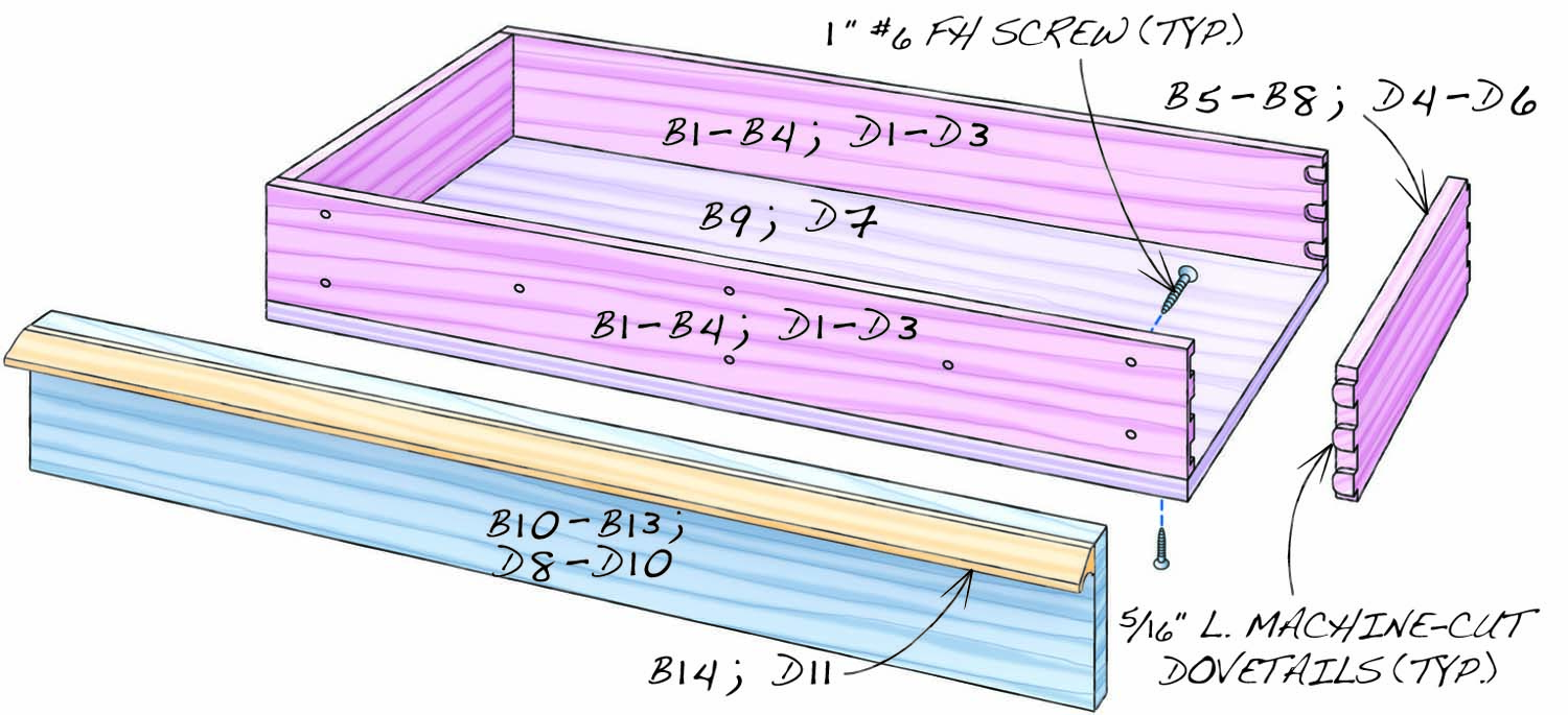
Fig. F. Drawer Construction
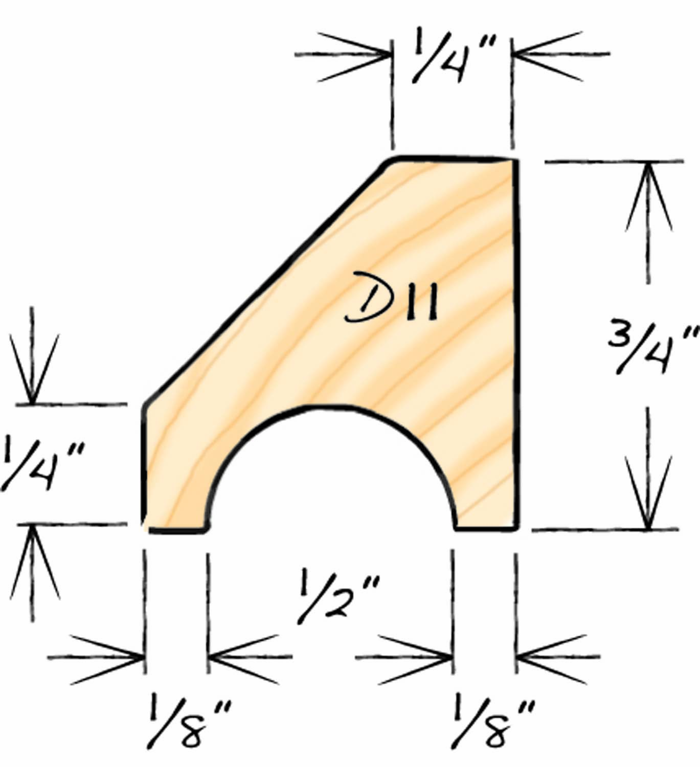
Fig. F2. Drawer Construction
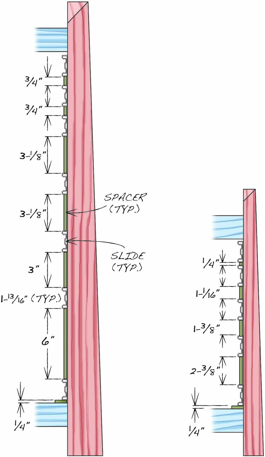
Fig. G. Drawer slide locations
Glue up blanks for the legs (A1, Fig. A, C1, Fig B, Cutting List). Use 8/4 stock, so the tapers won’t cross the glue line on the base cabinet legs. When the glue has dried, mill the blanks to their final square dimensions and cut them to length.
The two outside faces of each leg will be tapered (Fig. C). Orient the grain patterns as you like, and then mark the inside corner (between the two sides that won’t be tapered) on both ends of each leg. These marks tell you which sides of the leg to taper and make it easy to distinguish between the tapered and non-tapered sides after the tapers have been cut.
Lay out the mortises on the front inside face of each front leg blank. Then use a mortiser or a drill press equipped for mortising to cut square-shouldered mortises. Another option is to drill overlapping holes to the proper length and depth of the mortises using a 3/8″ Forstner bit. Square the sides of the mortises with a chisel and round the ends of the rails’ tenons to match the rounded ends of the mortise.
Taper, Chamfer and Miter
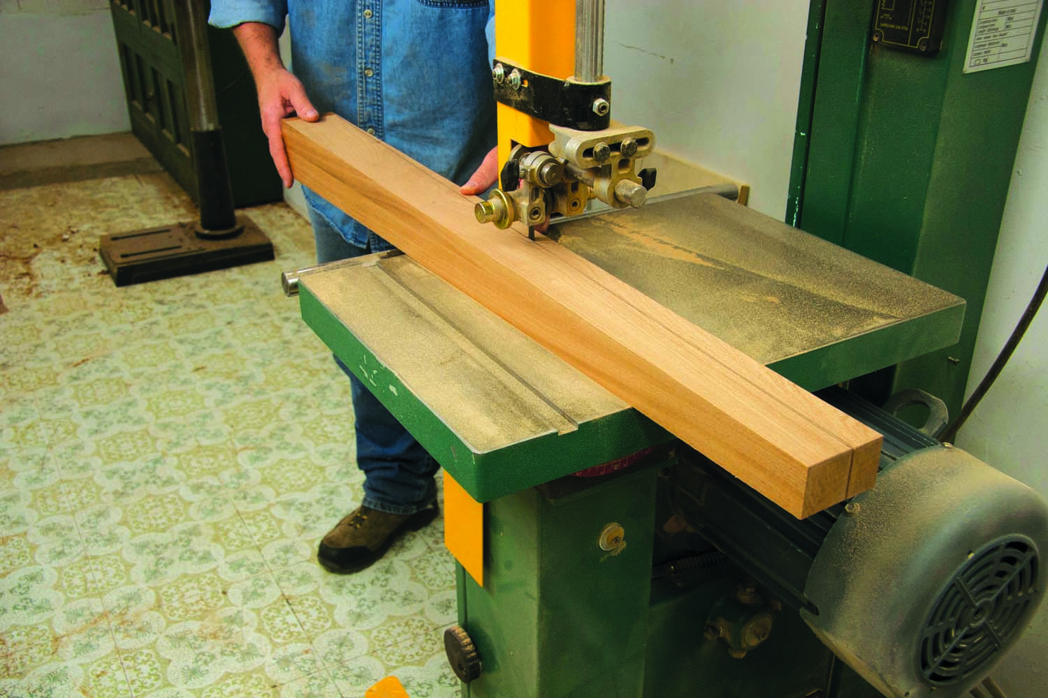
Photo 1. Taper the two outside faces of each leg on the bandsaw. Remove the saw marks by jointing, hand-planing or sanding.
Draw the taper on one outside face of each leg. Bandsaw these tapers and then draw the second taper on each freshly cut face, using the end marks made earlier to assure these adjacent tapers are correctly located. Cut the adjacent tapers (Photo 1). Then smooth both tapers on each leg using a hand plane or jointer. Save the wedge-shaped offcuts to use as cauls when gluing and assembling the cabinets.
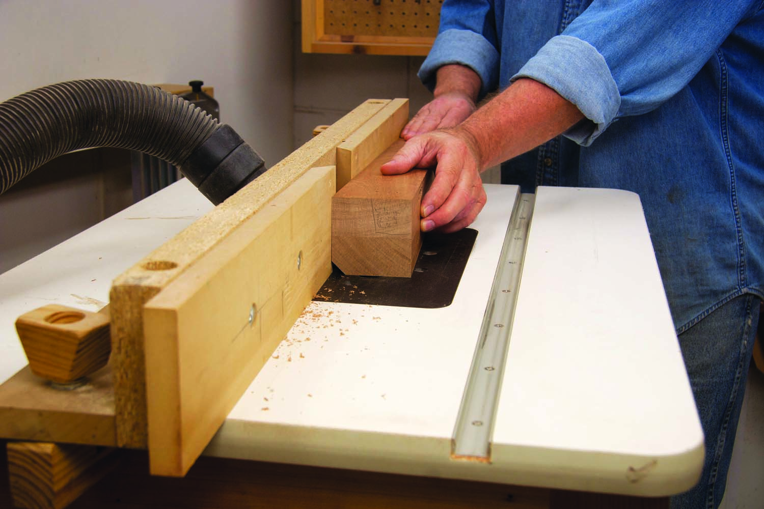
Photo 2. Chamfer the tapered outside corner of each leg.
Chamfer the legs’ tapered outside corners (Photo 2). Then use a miter saw to cut the decorative 45° miter at the top (Photo 3). This cut should connect each leg’s opposite corners. If the cut’s a bit off, make minor adjustments by twisting the leg.
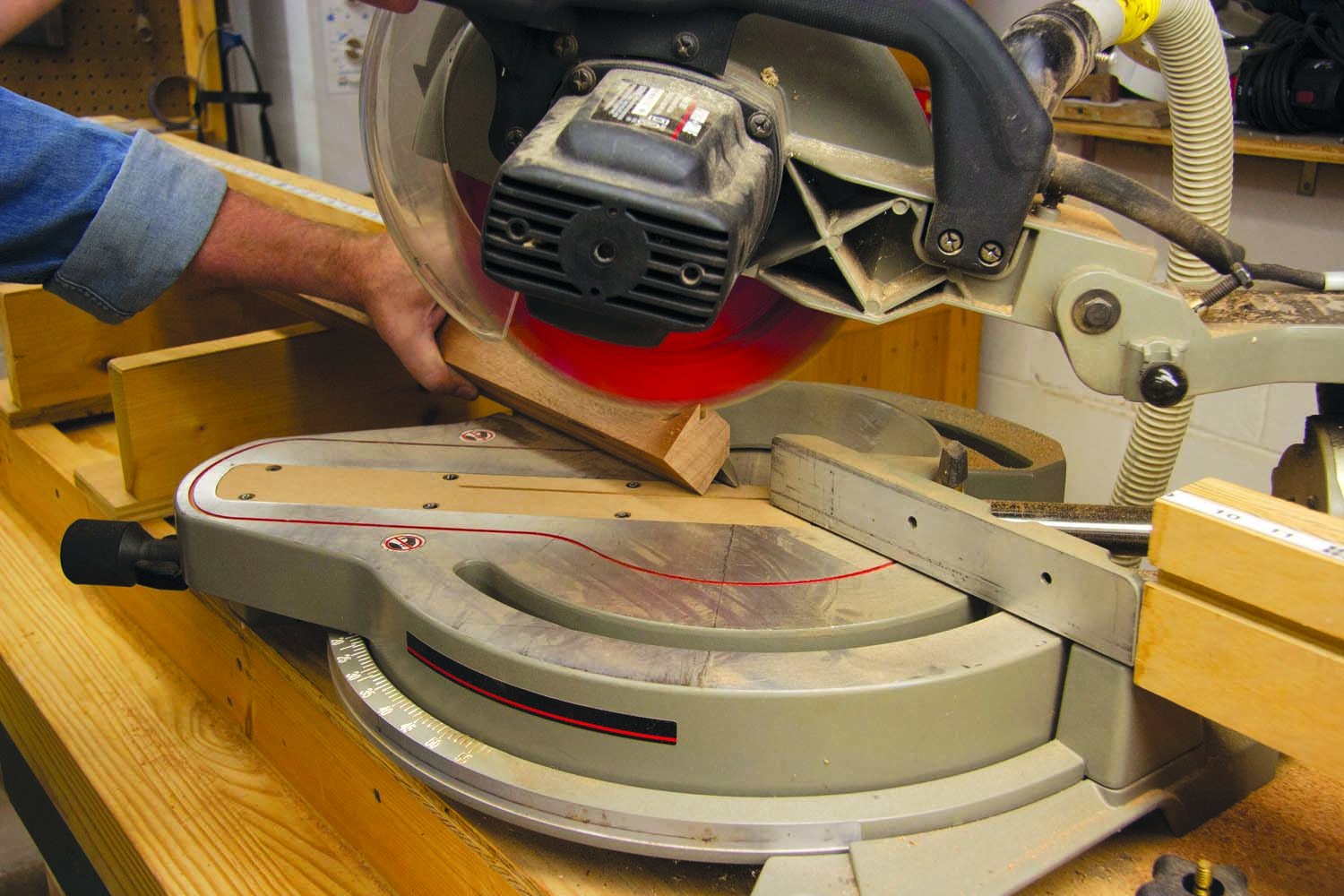
Photo 3. Miter the top of each leg for a distinctive look. Position the chamfered corner against the saw’s fence and bisect the opposite corners of the leg’s square top.
Mill Rails and Stiles
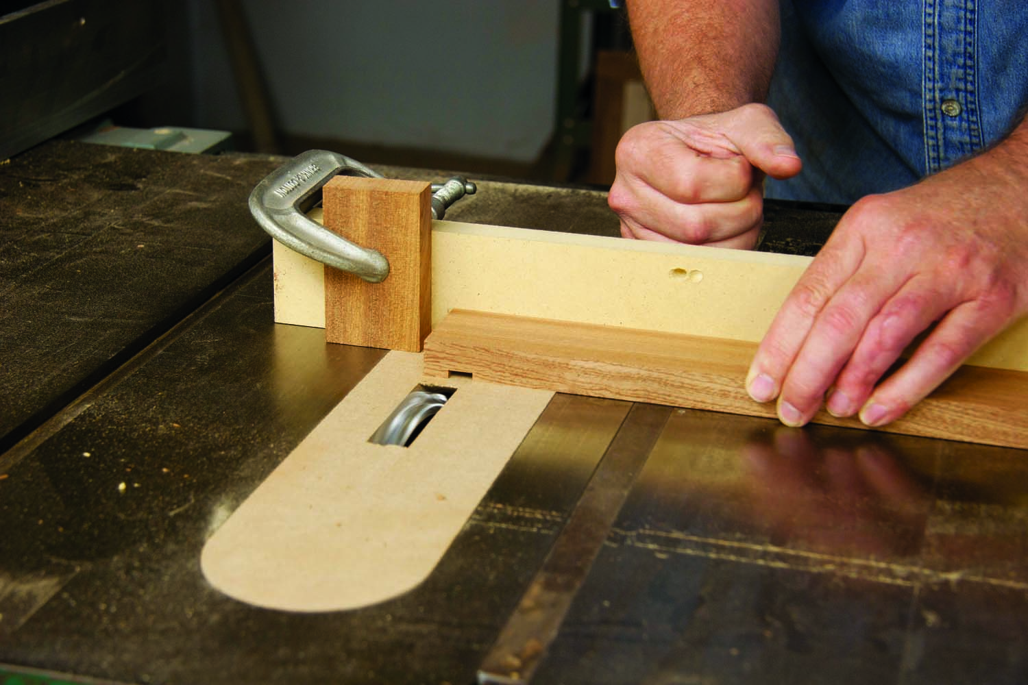
Photo 4. Cut tenons on the front rails to fit the leg mortises, using a dado set and a miter gauge with a long fence and a stop. Each tenon cheek requires two passes.
Cut the front rails (A2, C2) to final dimensions. Then cut 3/8″ thick x 1″ long tenons on both ends of the base cabinet’s front rails (Photo 4). Stand the rails on edge to cut the tenons’ top and bottom shoulders. Reposition the stop block to cut the 3/4″ long tenons on the top cabinet’s front rails.
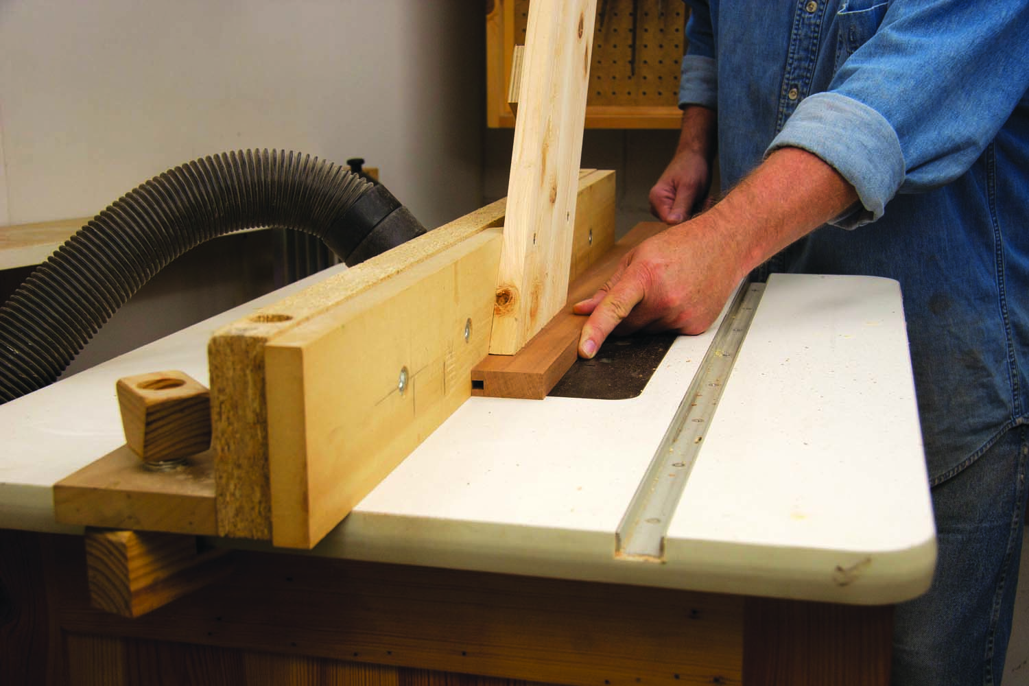
Photo 5. Cut tongue-and-groove joints to assemble the side and back panel frames. The rails’ grooves in the rails are offset so the assembled joints will flush on the back.
Cut the back and side rails and stiles (A3–A5; C3–C5) to final dimensions. Note that the rails are thicker than the stiles. Rout a centered 1/4″ wide groove in the inside edge of each stile. Then cut tenons on both ends, sized to fit the groove (Fig. E). Go back to the router table to rout offset grooves in the rails (Photo 5). Use same setup as for the stiles and make sure to position the rails’ inside faces on the table, so the assembled joints will be flush on the back. Finish by beveling the rails’ outside edges (Photo 6).
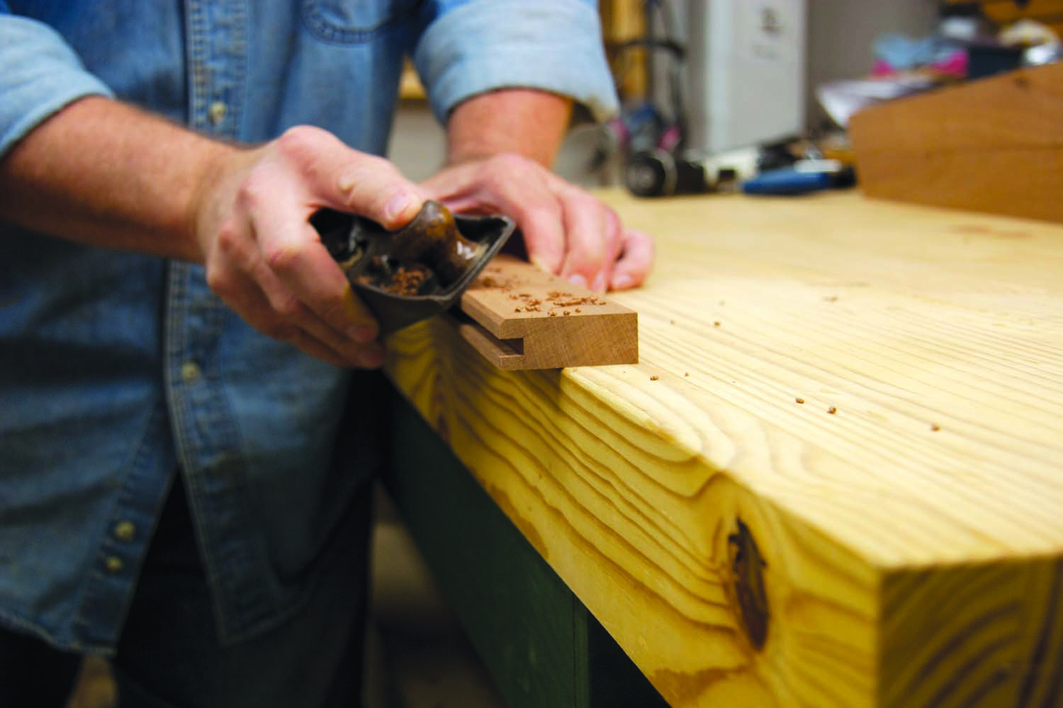
Photo 6. Bevel the outside edges of all the rails. The bevels ease the transition between the wide rails and narrow stiles.
Assemble Frames
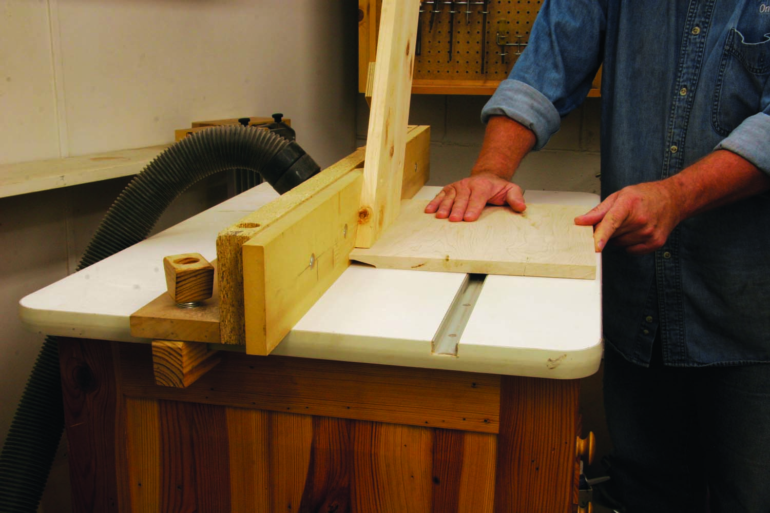
Photo 7. Shape each panel with a panel-raising bit. Complete the cut in several passes, by incrementally raising the bit. Make sure the tongues fit the grooves in the stiles and rails.
Glue up blanks for the back and side panels (A6, A7; C6, C7). Mill the blanks to final thickness and cut them to final width. Outfit your tablesaw with a crosscut sled to square the blanks and cut them to final length. Then use a panel-raising bit to shape the edges (Photo 7). The panels’ tongues should slip smoothly into the grooves in the rails and stiles. It’s easy to substitute 1/2″ maple plywood for the panels. Simply rabbet the back of each plywood panel to create the tongues.
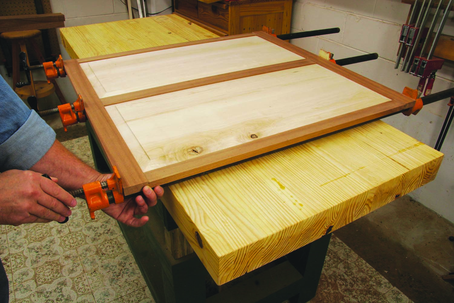
Photo 8. Check the outside edges to make sure the stiles and rails are flush when you glue each panel frame. Measure the diagonals to verify that the frame is square.
Dry fit each frame-and-panel assembly to make sure the parts fit properly. Gather the necessary clamps and lay everything out so the gluing process proceeds smoothly. If you’ve made solid-wood panels, brush glue on the stiles’ tenons only; then install the panel and assemble each frame. Solid-wood panels can’t be glued in, because they must be free to expand and contract. Plywood panels, on the other hand, can be glued in. Make sure the stiles and rails are flush and the assembled frame is square when you apply the clamps (Photo 8).
Glue the Carcass
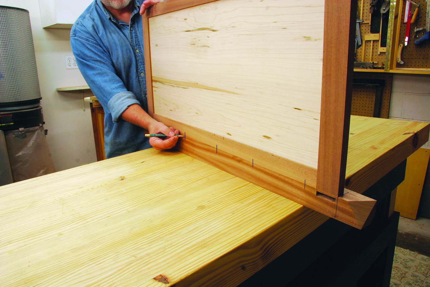
Photo 9. Mark biscuit slot locations after positioning each panel frame on the appropriate leg. Use a registration line to align the top of the frame with the top of the front rail.
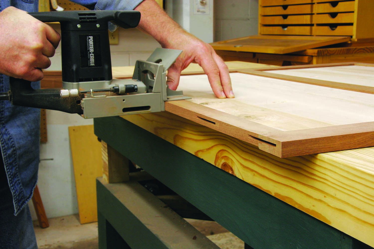
Photo 10. Cut slots for biscuits in each panel frame. Use the same setup to cut slots in the legs, so all the inside edges will be flush when the cabinet is assembled.
Draw registration lines to indicate the top of the rails on all the legs. Then lay out the biscuit slots on each leg and panel (Photo 9). Stagger the slot locations on adjacent panels. Then cut all the slots, using the same biscuit joiner setup (Photo 10). Dry assemble each side of the carcass with the top rails on the registration lines to make sure all the inside edges are flush and the joints fit properly.
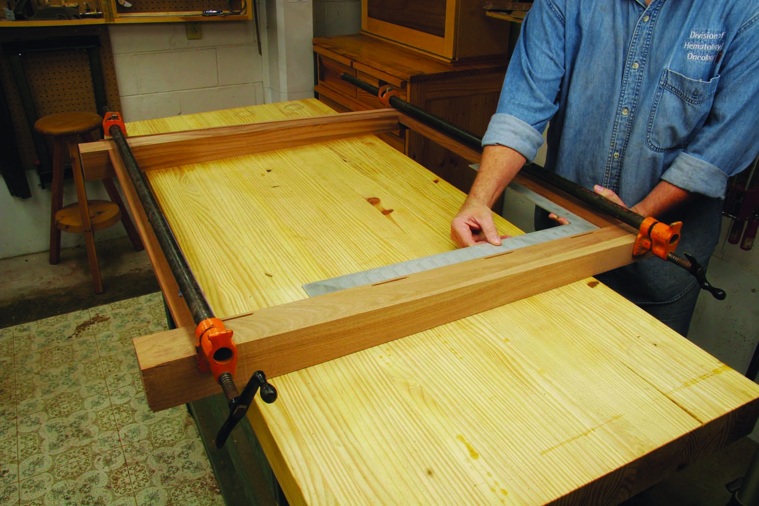
Photo 11. Glue together the front rails and legs, using tapered cauls to the correctly direct the clamping pressure. Make sure both rails are flush with their registration lines and the opening between the rails is square.
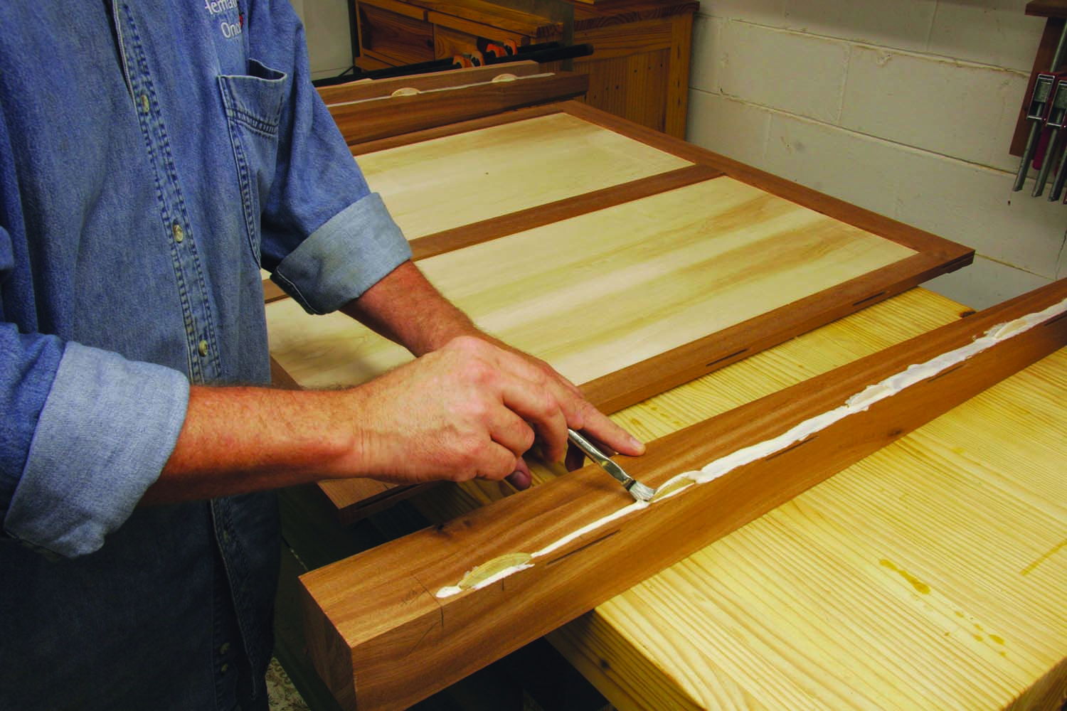
Photo 12. Apply glue along each joint when you glue the back panel between the back legs. Use the same registration and clamping methods as for the front legs and rails.
Glue together the front legs and rails (Photo 11). This assembly creates the opening for the drawers and drawer fronts, so it must be absolutely square. Brush glue in the mortises and on the tenons and use the offcuts from tapering the legs as cauls. Next, glue together the back legs and panel frame (Photo 12). This assembly must also be square.
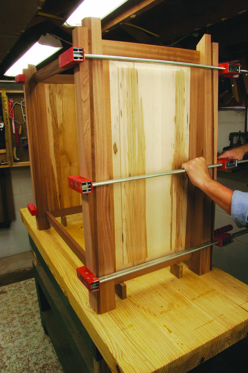
Photo 13. Glue the side panels between the front and back leg assemblies. Work on a flat surface and stand the panels on risers to position them at the proper height.
Glue the side panels between the front and back leg assemblies (Photo 13). This is a complex glue-up, so dry-assemble the carcass and think through the process of applying glue to the biscuits and along each joint before clamping the four assemblies together. You might decide to phone a friend or use glue with an extended open time. At the very least, free up your hands by taping the cauls to the legs and using spacers to position the side panels at the top registration lines. After everything is glued and clamped, make sure the carcass is square by measuring diagonally across the top and bottom on the outside or by checking at the top and bottom rails with a framing square on the inside.
Install Shelves
Install the cleats for the base cabinet’s bottom and top shelves (A8–A10) and for the top cabinet’s bottom shelf (C8—C10). Position the cleats for each bottom shelf so that the shelf will sit flush with the tops of the bottom rails. Fasten the cleats with glue and screws. Then brush glue on the tops of the cleats and set each bottom shelf in place. Drive nails or add weight (sandbag, toolbox, engine block, etc.) to hold the shelf in position until the glue dries.
The base cabinet’s top shelf sits 1/4″ below the top of the top rails. Install the cleats and this shelf using the methods described above. Installing the top shelf in the top cabinet is a bit different. Start by gluing the filler strips (C10; C11) flush with the top rails. Then turn the cabinet upside down. Apply glue to the bottoms of the filler strips, set the shelf in place and add weight to hold it in position until the glue dries. Here’s a tip: Apply the glue in the corners where the fillers meet the rails to keep it from squeezing out onto the shelf’s top face.
Installing heavy-duty casters is optional (Fig. D). Each caster supports 150 lbs. Turn the base cabinet upside down and drill holes in the bottom of each leg to house the caster and its socket. Adjust the holes’ depths to increase or decrease the caster’s exposure.
Make the Drawers
The drawers consist of boxes with applied fronts (Fig. F). The boxes assemble with 5/16″ long half-blind dovetails cut with a router and a standard dovetailing jig. Adjust the part sizes as necessary if you use different joinery. Mill and cut the box parts (B1–B9; D1–D7) to final dimensions. Then rout the dovetails. Glue together each box and immediately fasten the bottom with glue and screws—the applied bottom automatically squares each box. The drawers operate on full extension slides. Locate and install the drawer-box parts of the slides flush at the front of each box and 15/16″ on center from the bottoms (Fig. G).
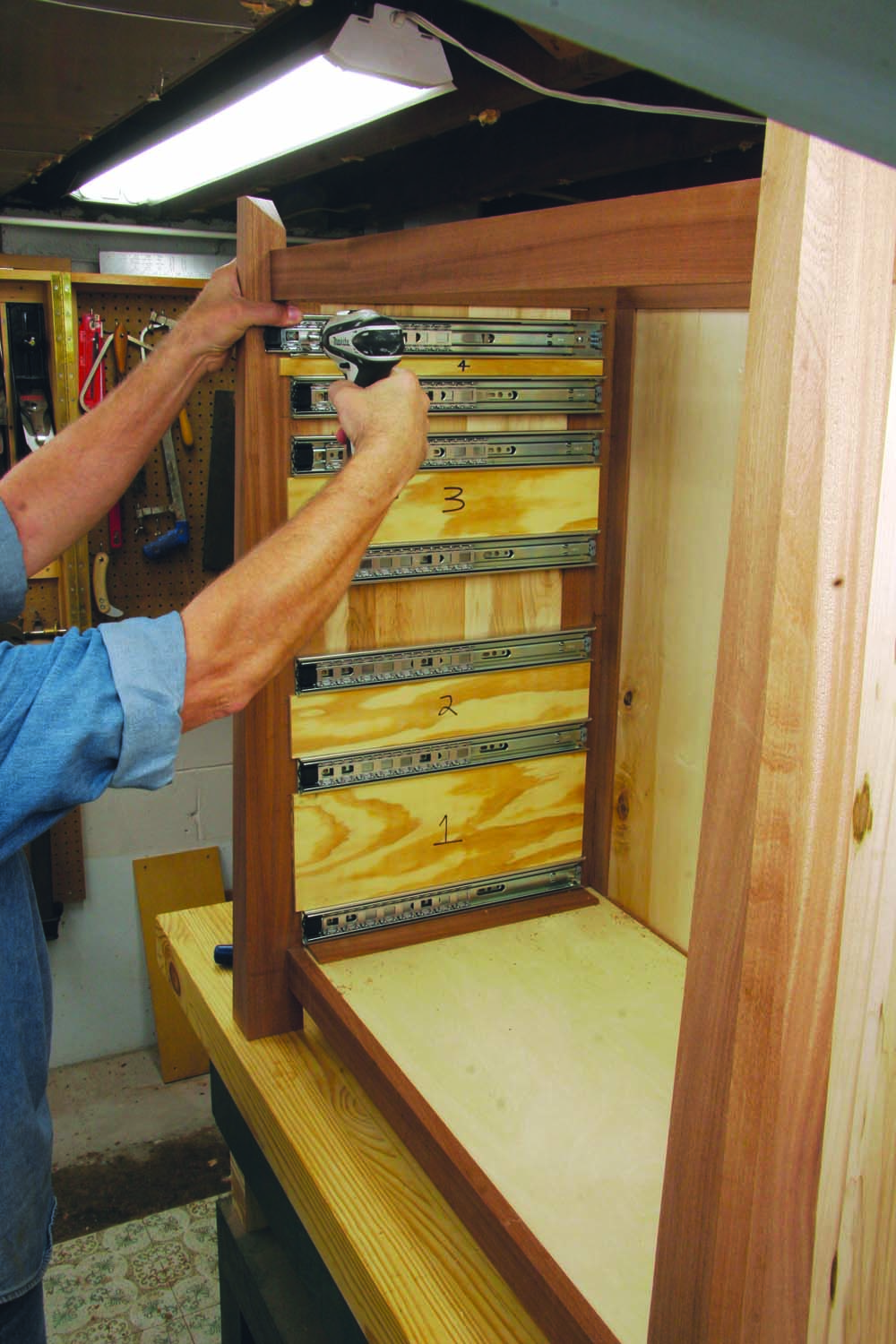
Photo 14. Use spacers to install the drawer slides in the cabinet. This method guarantees that every slide will be level and at the correct height. Some spacers are used more than once. Base cab spacer widths: Bottom: 1/4″; #1: 6″; #2: 3″; #3 3-1/8″; #4: 3/4″
Inside the cabinet, use spacers to locate each slide at the proper height (Photo 14). Install the slides flush with the back edge of the front legs. Mount the drawer boxes on the slides in the cabinet, check their operation and make any necessary adjustments. Note: the assembled drawer slides will be flush with the drawer bottoms.
Mill the drawer fronts (B10–B13; D8–D10) to final thickness and cut them a little longer than their final dimensions. Rip and joint all but the two top drawer fronts to final width. Leave these two fronts (B10; D8) about 1/4″ extra-wide.
Mill 3/4″ x 4″ wide blanks for the drawer pulls (B14; D11; Fig. F). Cut these blanks at least 1″ longer than the drawer fronts. Install a 1/2″ core box bit in the router table and set the fence 3/8″ away from the center of the bit. Then rout a cove on each side of the blank that’s deep enough to provide a finger grip. Install a 45° chamfer bit to rout both edges of the blank. Complete these chamfers by in two or three passes by incrementally raising the bit. Use the tablesaw to cut the completed pulls from the blank.
Glue the pulls to the drawer fronts, flush at the top. Then cut the drawer fronts to length, 1/4″ less than the width of the openings in each cabinet.
Attach Drawer Fronts
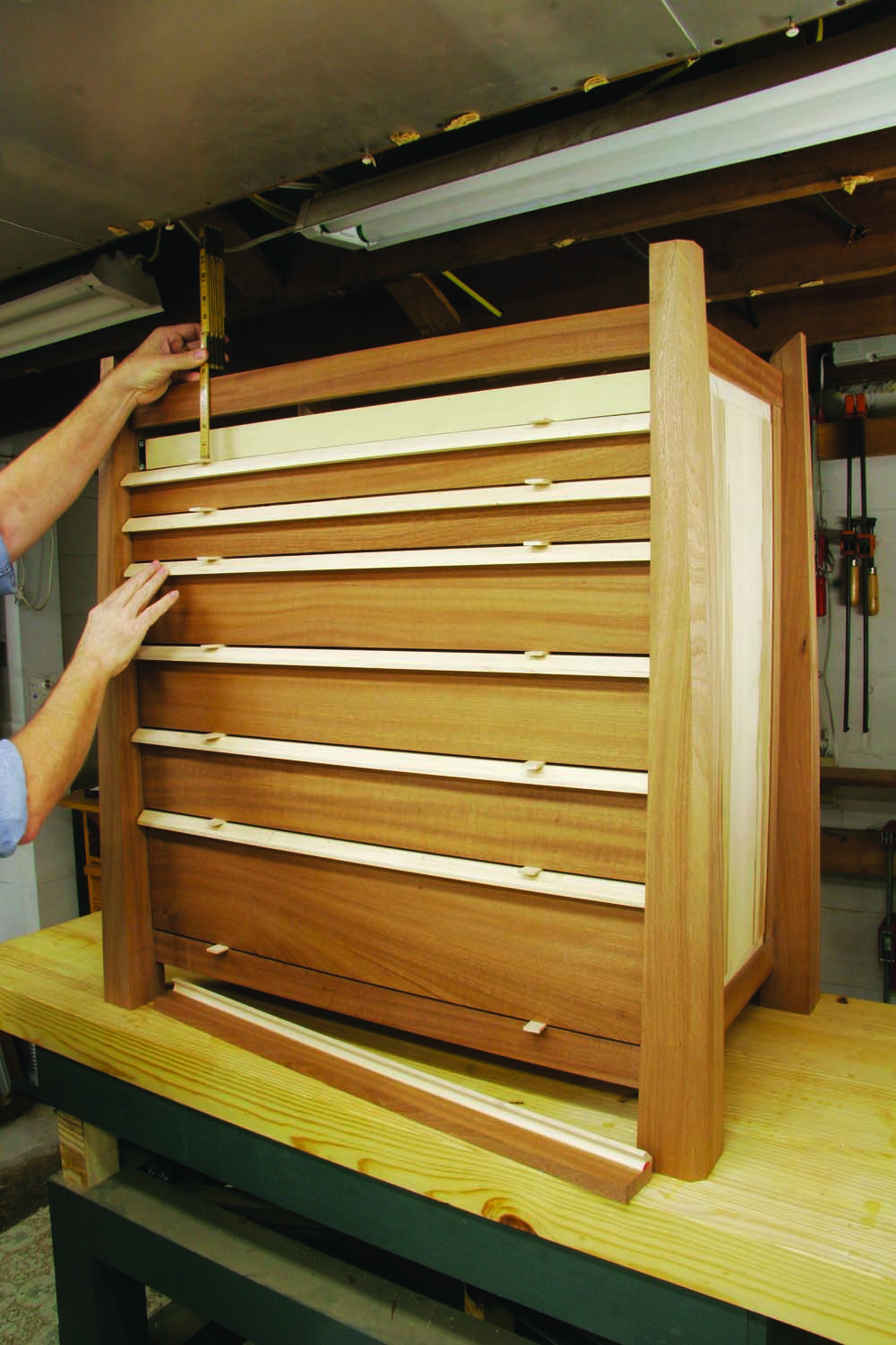
Photo 15. Create equal spacing between the drawer fronts by using spacers. Before cutting the top drawer front, measure the opening to confirm its proper size.
Use 1/8″ spacers to fit the drawer fronts to the cabinet (Photo 15). Place a pair of spacers on the top of the bottom rail. Then set the bottom drawer front on the spacers. Continue stacking spacers and drawer fronts until only the top drawer front remains. Measure between the spacer and the top of the opening, subtract 1/8″ and rip the top drawer front to this width. Install this drawer front, check the space at the top and make adjustments, if necessary. Then remove all the drawer fronts.
Adhere strips of double-sided tape on the front of each drawer box and station 1/8″ thick x 29″ long spacers on both sides of the cabinet opening to center the drawer fronts. As before, place 1/8″ spacers on the bottom rail. Set the bottom drawer front on top of the spacers and use the side spacers to center it. Then press the drawer front firmly against the drawer box, so it adheres to the tape. Apply clamps to securely hold the drawer front and then gently remove the drawer. Drill pilot holes through the drawer box and install screws to fasten the drawer front. Install this completed drawer in the cabinet and then install each ascending drawer front using the same method.
Construct the Lid
The lid is the same size as the opening in the top cabinet and rests the cabinet’s fill strips. Miter the corners of the lid’s rails and ends (E1; E2) while cutting them to final length. Leave these parts oversize in width. Gang together the end pieces to bandsaw their angled tops and remove the saw marks. Make sure the peaks remain centered. Then saw or rout 1/4″ wide x 1/2″ deep rabbets in the top inside edges of both pieces.
Bevel the top edge of each rail to match the slope of the end pieces. To determine the bevel angle, draw a perpendicular line on one of the end pieces from the bottom to its peak. Then set a sliding bevel square on the end’s angled top edge and align its adjustable arm with the line. Tilt the saw blade to this setting. Joint the beveled edge to remove saw marks. Then rip the rails to final width, so their profiles match the end pieces. Cut the rabbets on the rails’ inside edges using the same angled setting.
Clamp together the lid’s frame and measure between the rabbets to fit the panels (E3). Cut the panels to length. Then return the blade to the bevel angle and cut the top edge of each panel. Test fit the panels and mark their final widths. Then cut their bottom edges at the same bevel angle.
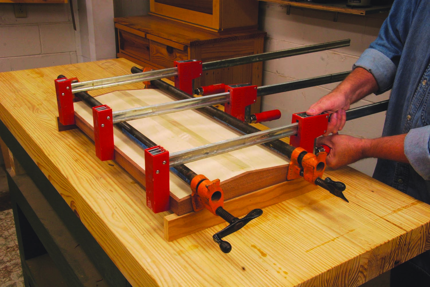
Photo 16. Glue the lid together in stages. Tape and glue the mitered joint between the panels and then immediately glue the panels to the ends. Finish the job by gluing on the rails.
Glue the lid together in stages (Photo 16). First, assemble the miter joint between the two panels and tape it together on the outside, so the panels open like a book. Spread glue on the open joint and in the rabbets in each end piece. Close the joint as you place the panels in the ends’ rabbets. Clamp these parts together. Then glue the rails to the ends and the panels to complete the lid.
Install the lid, using a continuous hinge that’s surface mounted on the lid’s back rail and the cabinet’s top back rail. When the lid is opened, the hinge will close.
Sand the cabinets and drawer fronts and finish them with several coats of shellac or lacquer. Then load the drawers and congratulate yourself: This may be the first time you’ve seen an uncluttered workbench in years!
Here are some supplies and tools we find essential in our everyday work around the shop. We may receive a commission from sales referred by our links; however, we have carefully selected these products for their usefulness and quality.