We may receive a commission when you use our affiliate links. However, this does not impact our recommendations.
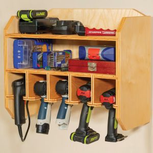
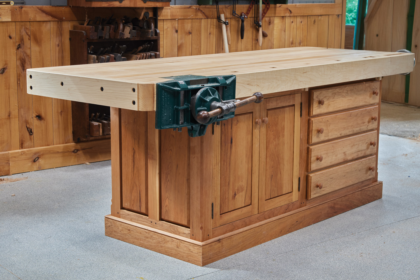 This shaker-style workbench combines cabinet storage underneath with a generous work surface up top.
Traditional Shaker workbenches appeal to me for two reasons. First, the long wide top offers space enough to work on almost any project, with enough room left over for everything else that we all find essential and keep ready to hand while we work. The carrier deck sized top brings out the Walter Mitty in my nature, playing carrier commander in my imagination. Secondly, and equally important, is the storage space offered by the enclosed cabinet that makes up the bench’s base. Whether your shop is large or small, no one, especially me, ever has enough storage space. I evaluate every tool cabinet and bench plan I read about with an eye for wasted unfilled volumes of space that could be better used. As I look back over the last few years in my own shop, my efforts have not revolved around fitting larger or newer tools into the space I use, but rather on constantly improving the organization and storage within the shop. The Shaker belief that keeping everything orderly and in its place, is a useful guide for a modern woodworker. The storage space incorporated in the base of this new bench will be filled before I know it.
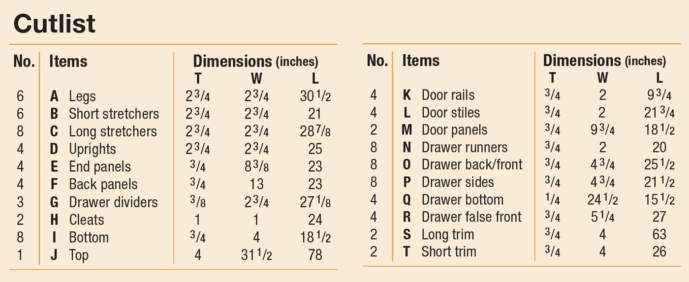
Cutlist and Diagrams
 Bench Design
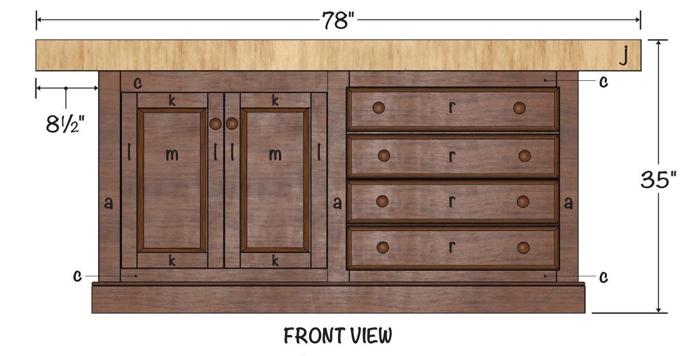
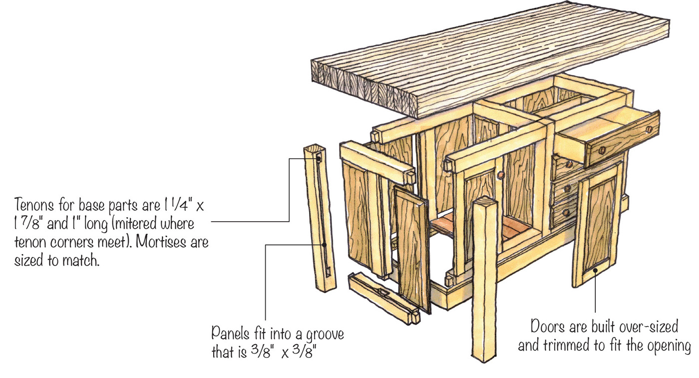
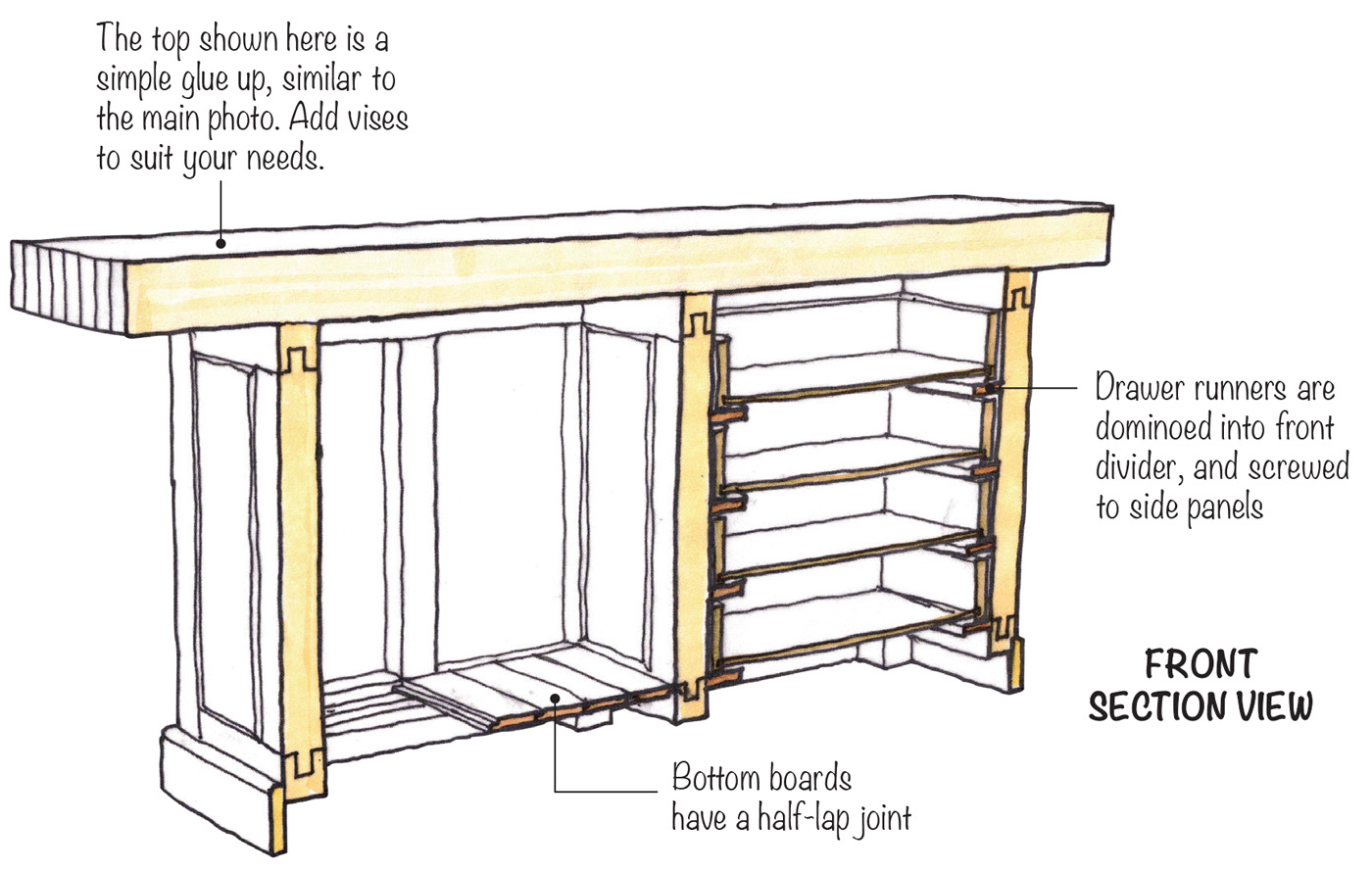
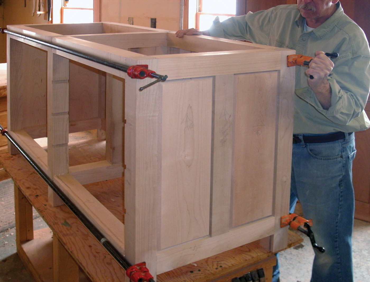
The Shaker bench I built is loosely based on a large Shaker bench found at the Hancock Shaker Village in Pittsfield, MA. I have always admired the ranks of drawers and doors that front that bench’s base. I scaled the bench down in length and overall mass to fit a space in my shop. For simplicity I modeled the frame of my bench’s cabinet base after a typical New England barn timber frame, like the one on my farm. I used standardized stock dimensions, and production methods to streamline parts manufacture and assembly. All of the cross section components share a common layout of their joinery, so that they fit together into three identical “bents” just as you find in a timber frame. The bents are connected by eight identical rails, which are tenoned into mortises cut in to the legs, or sides of each “bent,” to complete the basic frame of the cabinet.
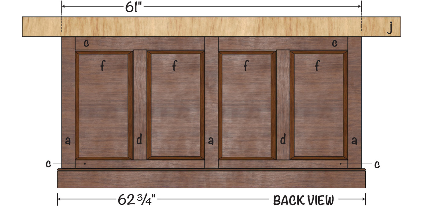
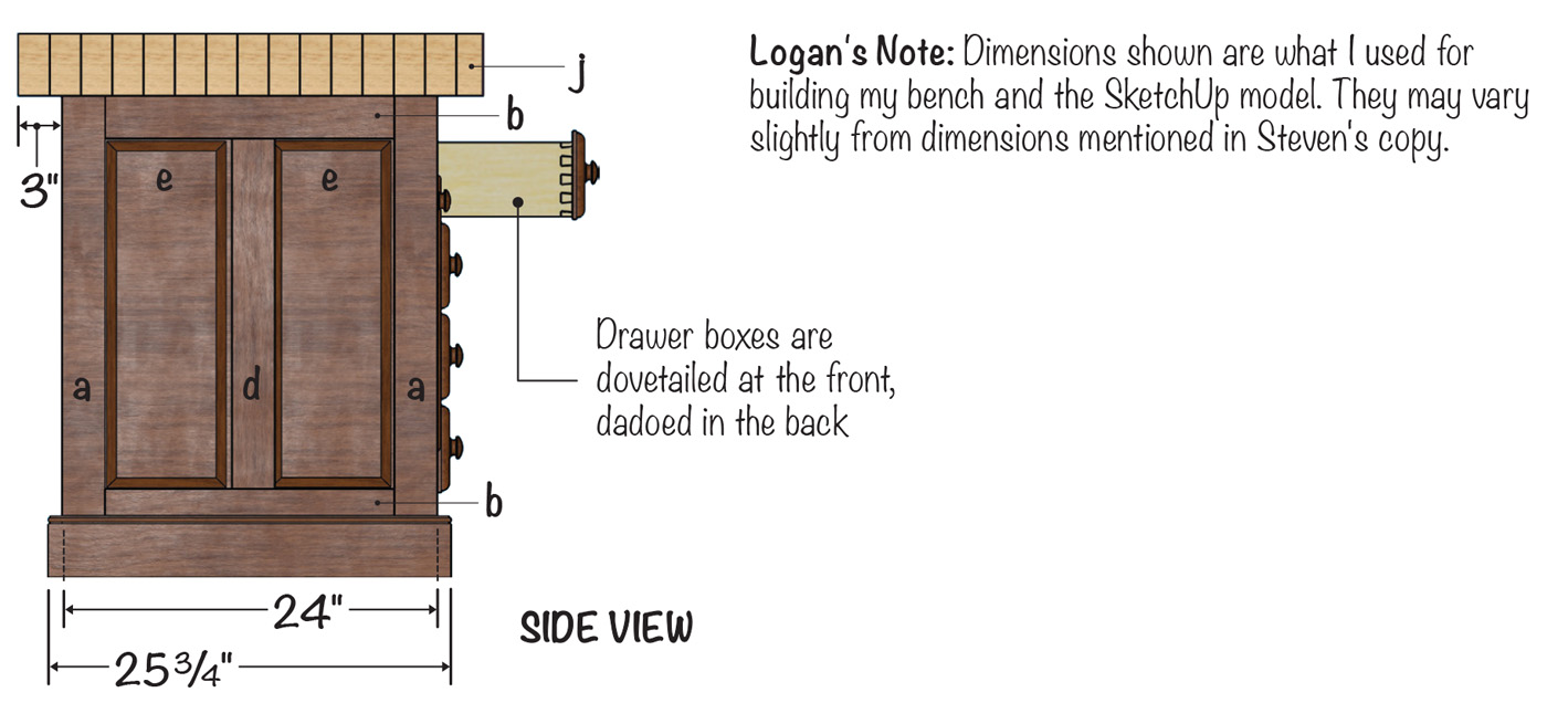
A key element of the design is the six legs which transfer working force from the bench top directly to the floor. This frame is strong and massive, but provides a great deal of flexibility in how the drawers and doors are finished out. I like the look of the original bench which inspired this one, with the double doors of one section flanked by a double rank of drawers. To reduce the length of my bench I eliminated one of the ranks of drawers, shortening the base by almost 30“. I like to work on all sides of a bench. And the bench is going to be placed where it can be viewed from all sides by visitors to my shop. So I am especially concerned that it look good from all angles. So I filled the side and back voids in the frame with raised panels.
The basic frame can be modified to accept varying combinations of drawers or doors. Want a bench with all drawers, or doors? Want doors on one side of the bench, and drawers on the opposite side? Want double fronted drawers that can be pulled open from either side of the bench? Any of these arrangements can be fitted within the basic frame of the bench I built.
Customize Your Own
As I mentioned before, Steven’s bench shown here fit everything I wanted for a bench for my shop. However, upon starting construction, I found it interesting, as I was using different methods than the author described (exactly as I expect our readers to do with each project — gather the basics, then build it how suits you in your shop).
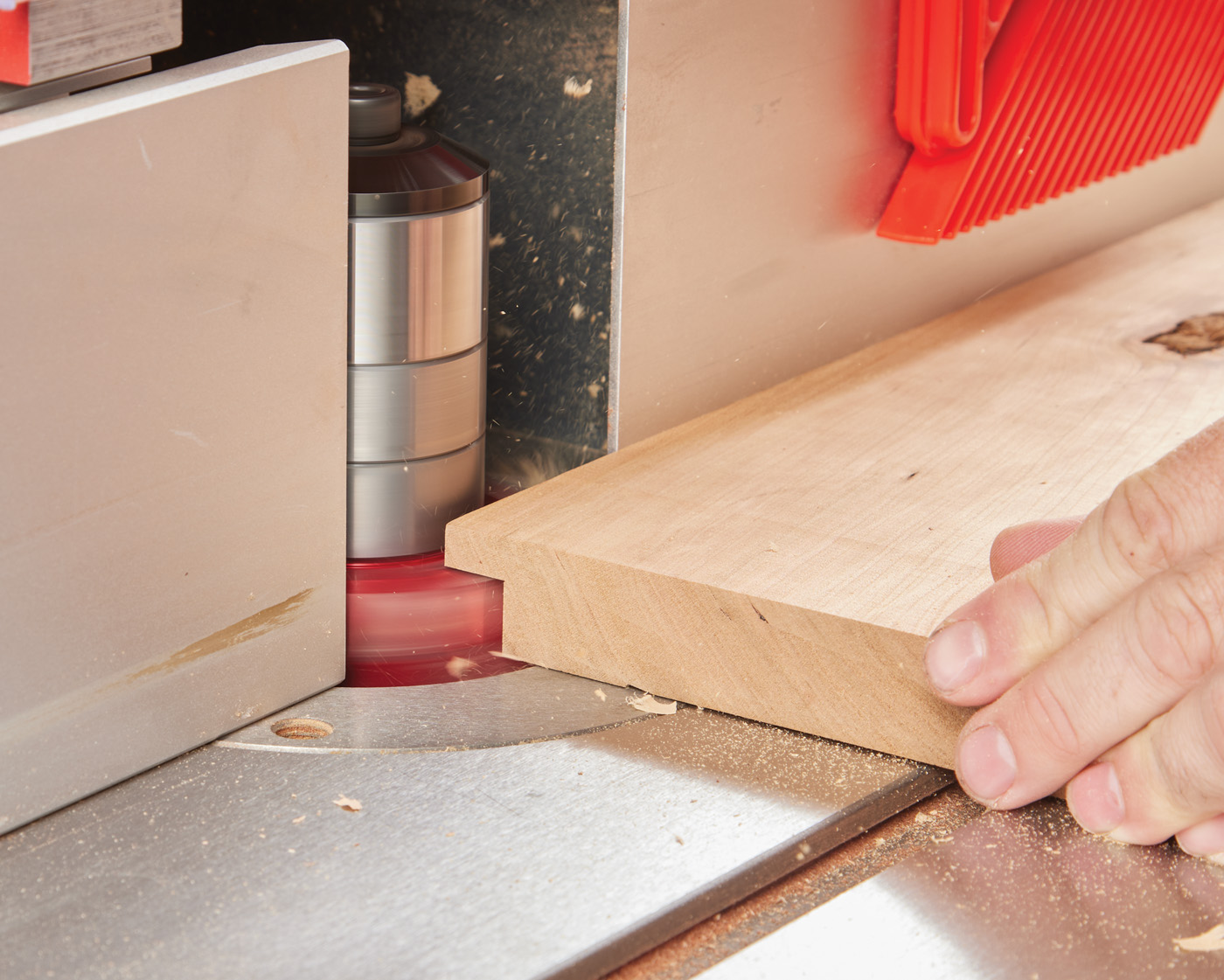
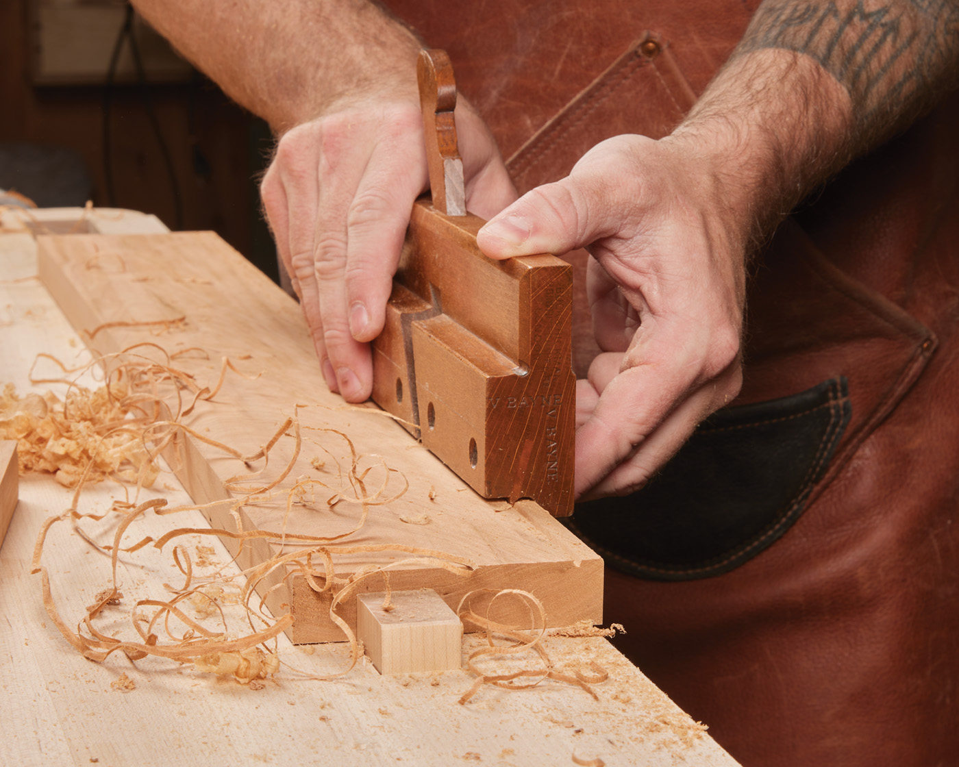
A The panels for the base and the doors are made in a two-step process. First, rabbet the edges of the panels.
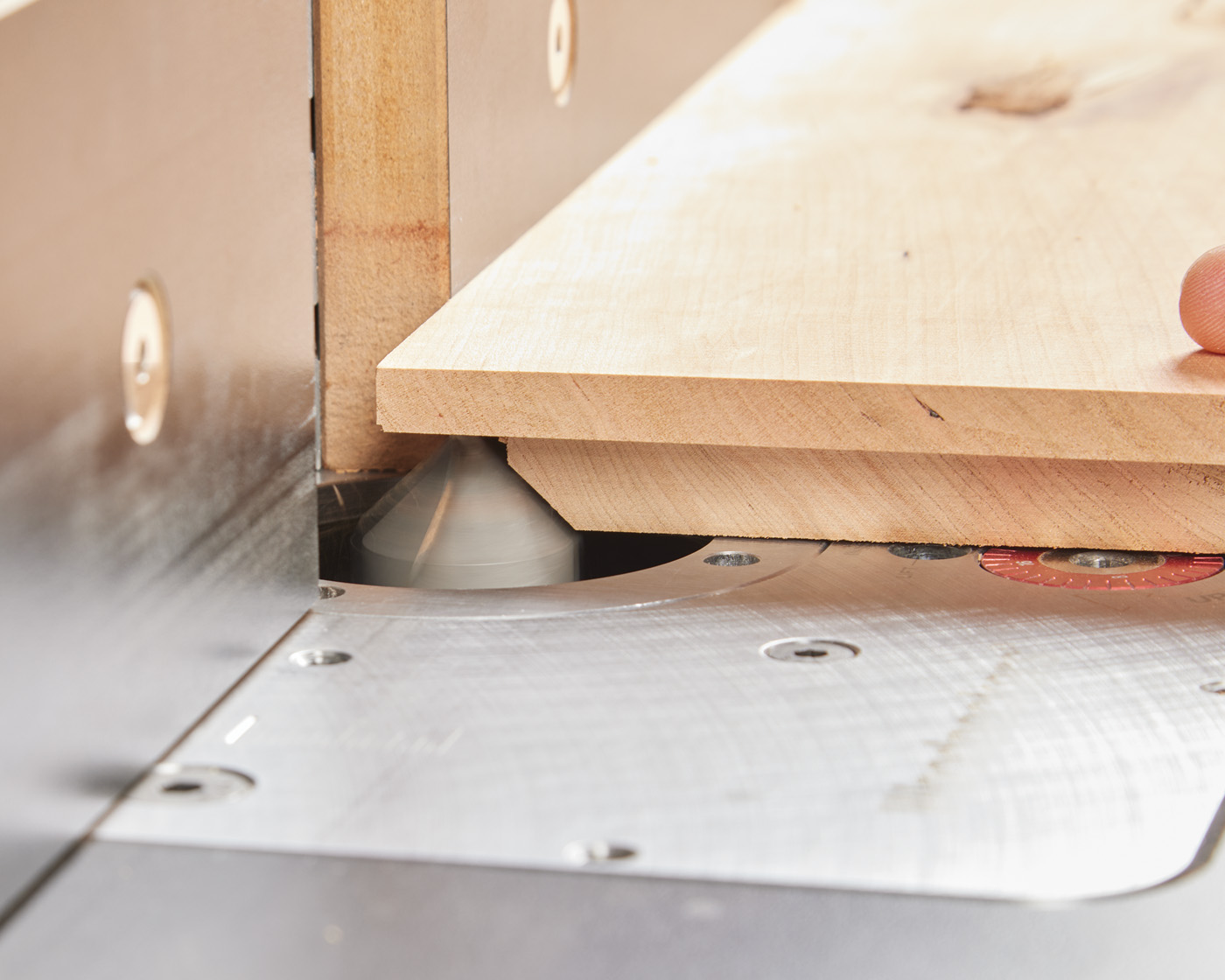
B Then, set up a 90° V-bit to cut the chamfer along the rabbeted edge.
There were several main differences. First, I used the PantoRouter to do all the joinery. Next, I created all of the panels at the shaper instead of the table saw. See photos A and B. This was a two-step process. First, create the rabbet, and next cut the 45° chamfer using a V-bit.
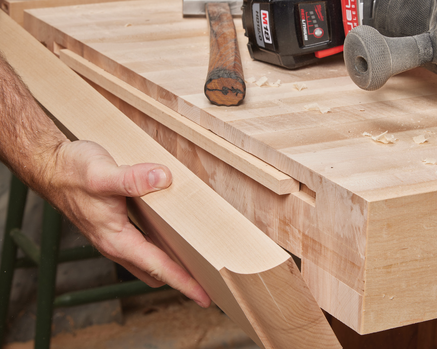
C A spline keeps the top flat in relation to the end cap.
D A molding plane makes quick work of the workbench beads.
For my bench top, I used a different construction method. I glued up my top out of 3“ thick stock. I affixed “breadboard” ends using a spline that I routed in to the top and cap (Photo C). When it came to some of the other parts (such as the trim and the bottom of the door cubby), I decided to apply a beading plane. I have to say, a vintage plane like this is a joy to use. – Logan Wittmer
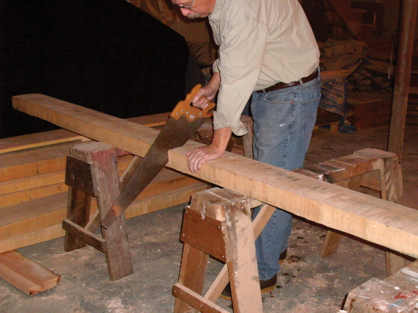
1 The workbench stock starts as 12/4 material and is broken down to size.
Building the Base
I milled the base components from 12/4 soft Maple. After crosscutting the rough stock to approximate lengths, I jointed one face and edge of the stock and ripped the pieces slightly oversized. Using the jointer again I jointed two adjacent faces of each rough-sawn piece straight and square to each other. Taking the time to re-flat face and re-square each freshly sawn part eliminates any twist or bowing created by internal stresses in the wood. These are released as the wider stock is cut into smaller widths. The stock was then passed through the thickness planer to clean up the last two rough faces and bring the material to final dimension. I cut the individual components to length, allowing extra length on the center stiles, rails, and stretchers for tenons. After the stock was prepared, I oriented the best face to show and arranged the legs to best match their grain patterns across the front and rear faces of the base. I marked each piece to maintain grain matching during the milling of the the mortise and tenons and assembly.
 I laid out the mortises on the legs, rails, and stretchers and milled them using a 1“ diameter Forstner bit and a temporary fence mounted on my drill press. The shoulders of the mortises were cleaned up with a bench chisel. The mortises were cut 11/16“ deep to allow for glue compression and to keep the 1“ long tenons from bottoming out and preventing the shoulders of the stiles, rails, and stretchers from drawing up tightly against the mortised components. All of the mortises open on to their adjacent mortise. This requires that the meeting corners of both meeting tenons need to be cut back at a 45° angle to let both tenons seat fully.
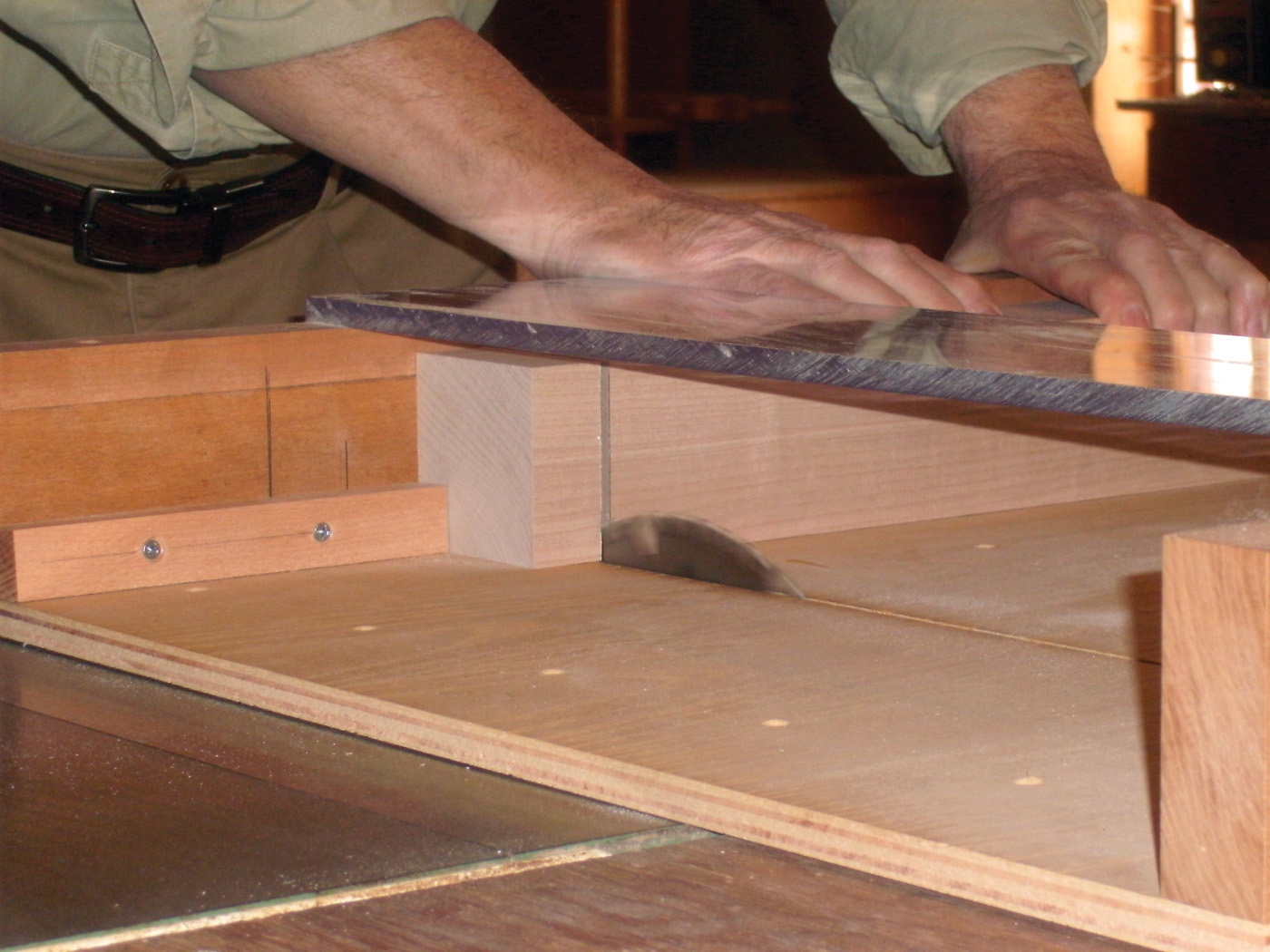
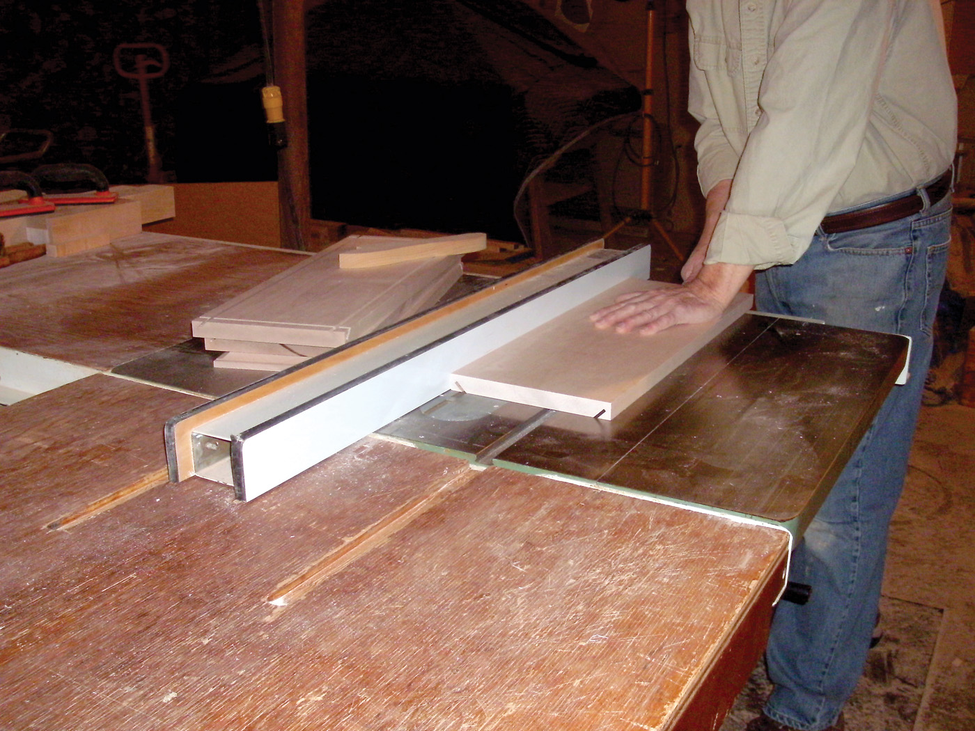
3 Tenons are sized at the table saw.
I cut the tenons using a tablesaw. Set the T-Square fence so that the distance from the fence to the outside face of the blade measures 1“, the length of the tenons being cut. Cut the shoulders of the tenons in two setups. First set a crosscut blade to the depth of the tenon’s side check, 3/4“. Then cut the shoulders of the side cheeks on opposite faces of each part being tenoned. Reset the blade height to 7/16“ and cut the top and bottom shoulders of the tenons on the remaining two faces of the stock. I then changed blades and used a dado blades set, to waste out material and create the tenon’s four faces. Repeating the two step operation used in cutting the tenon shoulders, cut first the tenon cheeks with the dado set at one height, then reset the blade height and form the top and bottom faces of the tenon. If you are not concerned about the possibility of tear out caused by the use of a dado set to cut the tenons, you may skip pre-cutting the tenon shoulders with a cross cut blade, and go directly to cutting the tenons with the dado set.
4 The panels are beveled before the tongue is cut.
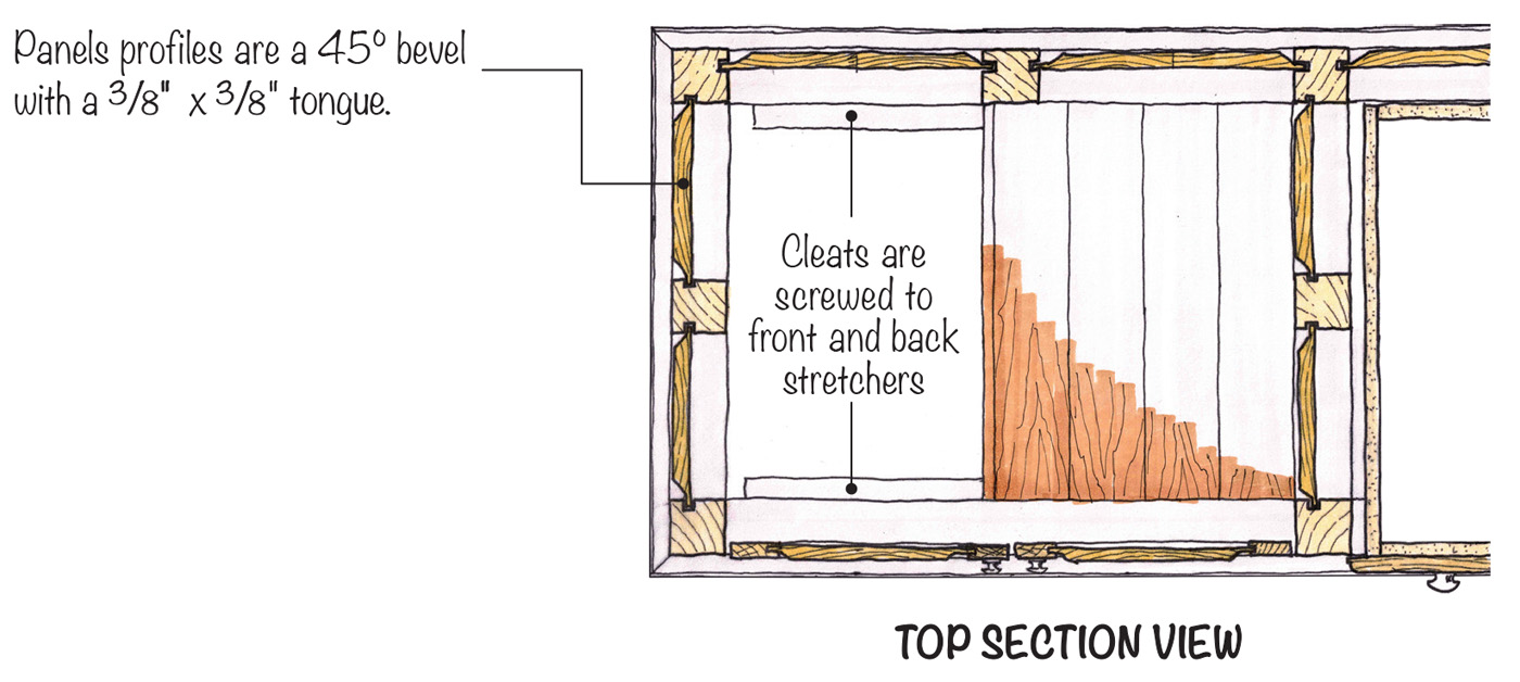
To determine the dimensions of the raised panels, I dry assembled the bench base, first fitting the legs, center stiles and rails together to make the bents and then added the stretchers. This allowed me to double check my “as” built dimensions against the planned dimensions. After measuring for the panels, I laid out the panel grooves on the frame members. I marked the faces to be grooved prominently to prevent mistakenly cutting a groove in the wrong face of one of the base components. I then disassembled the base and plowed the panel grooves with a dado blade on my table saw. I didn’t worry about stopping the grooves in the legs because the base molding would hide the exposed grooves at the bottom of the leg.
5 Route the sliding dovetails.
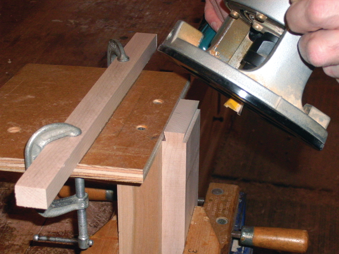
Raised panels were glued up from 5/4 soft Maple and thicknessed to 3/4-7/8“. I cut a raised panel profile of 45° in two passes using the table saw. I used a dado blade to cut the 1/4“ wide by 5/8“ deep rabbet that forms the tongue on the outside edges of each panel. I set the T-Square fence against, but not quite touching the dado blade, to act as a guide as I ran the panel good face down in four passes over the blade to form the rabbet. Changing the dado set for a fine toothed saw blade, I set the blade at an angle of 45°. I reset the T-Square fence and adjusted the blade height to allow the angled blade to just meet the corner of the rabbet previously formed. Four passes again with the best face of the panel face down on the saw’s table, with the tongue pressed against the fence rips away the waste from the rabbet to form the finished 45° profile. After cutting the raised panel molding I used a piece of scrap wood cut at a matching angle and wrapped with sand paper to clean up the molding.
6 Glue up the individual
assemblies.
7 After the assemblies are dry, glue up each segment together, to create the entire bench base.
8
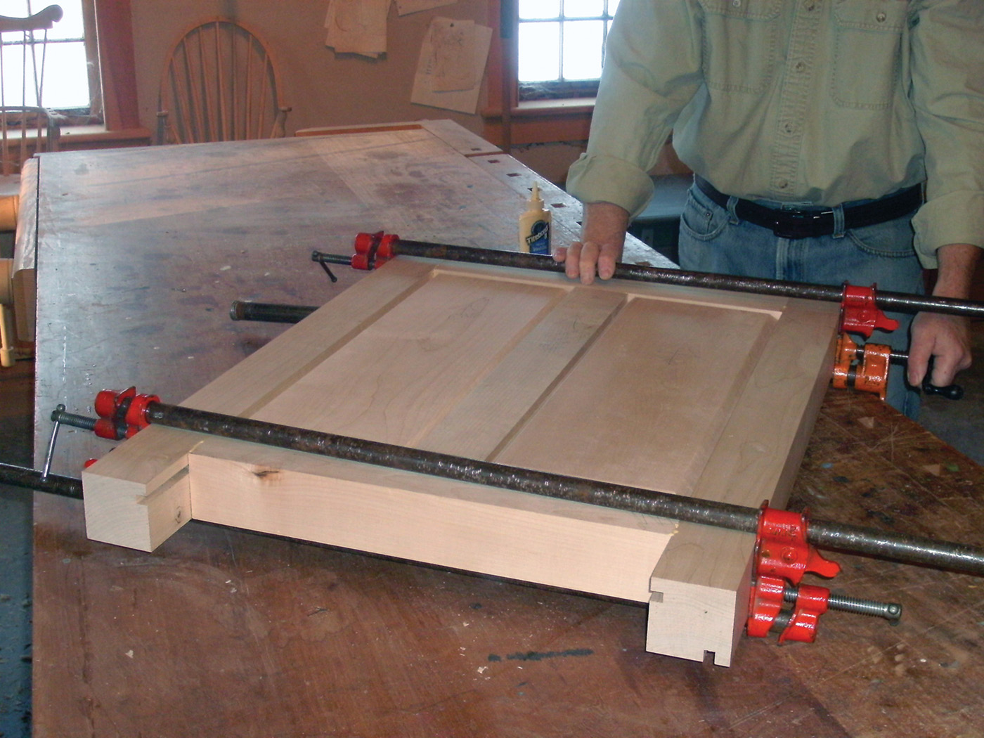
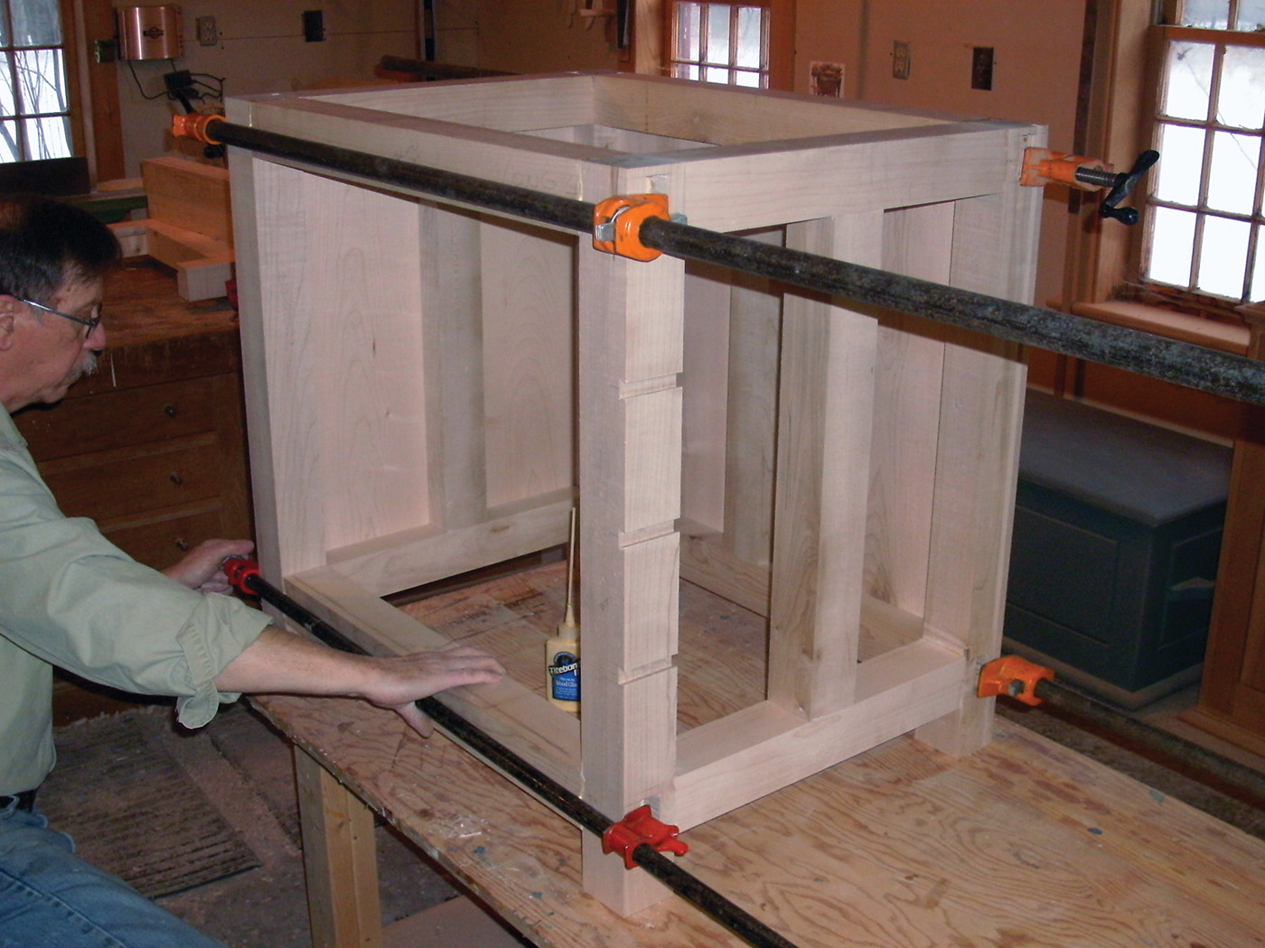
Glue up of the base is straight forward. Dry fit each panel into its grooves to test the fit of everything before adding glue. Glue and clamp up the components of each of the three “bents”, two legs, center stile, top and bottom rails, and two raised panels. Check for square and leave to let dry. With the three bents assembled, assemble one bay of the frame at a time. After a final double check of the fit of the components, i.e. check for dried excess glue squeeze out in the open mortises, glue two of the bents together with four of the stretchers. If one pair of the stretchers is part of the back of the bench, remember to install that section’s center stile and raised panels prior to fitting that pair of rails into the base. I glued together the back rails with their center stile and inserted the raised panels as a subassembly prior to assembling the bench bay. This let me check the rail section for square and let the glue set up making final assembly of the base bay easier. With one bay clamped up and left to dry, adding the final four rails, and panels is a simple step completing the basic base frame.
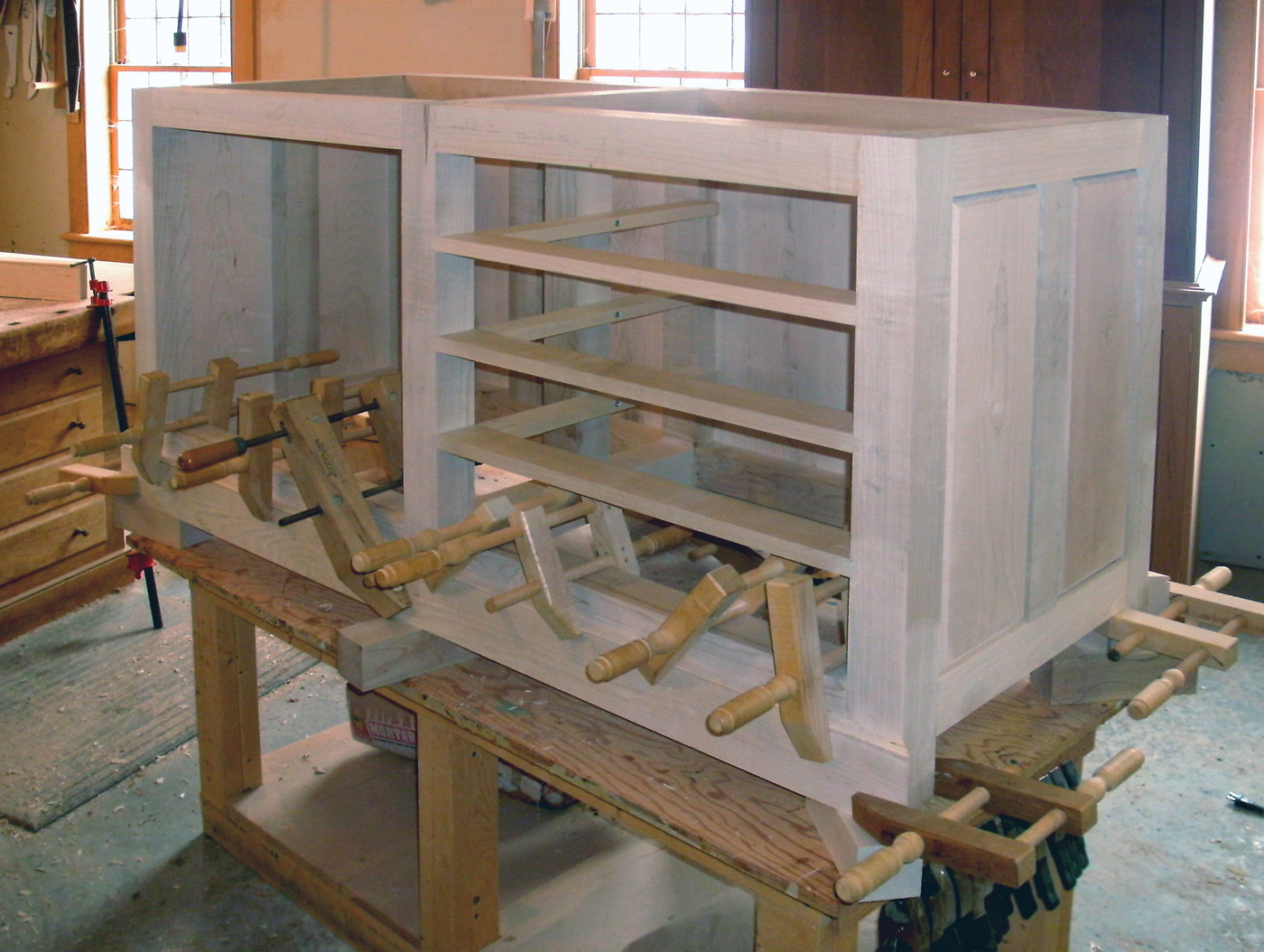
Adding Drawer Dividers
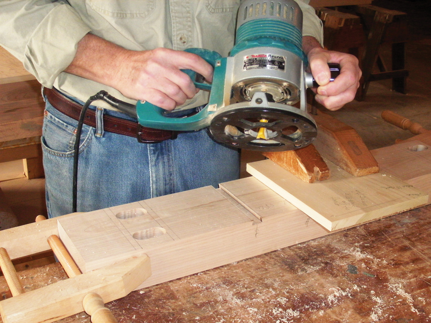
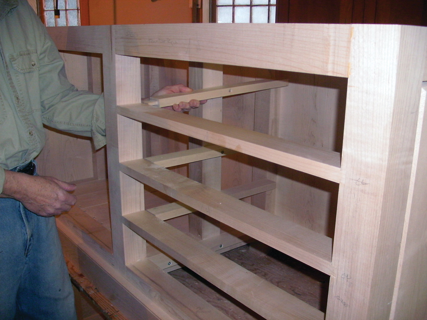
To support the drawers I needed to install dividers, runners, and guides. Sliding dovetails secure each divider to the legs and add more strength to the massive base. On an earlier version of this bench I assembled the base and top and put the bench to use before coming back and installing drawers and doors. This meant that I was forced to rout the sliding dovetails while holding the router in a horizontal axis and sliding the kicking bucking tool along a temporary fence clamped to the vertical leg. Not a woodworking technique that is safe for family viewing. On this version of the bench I laid out the drawer divider location on the two legs that formed the sides of the drawer rank. I clamped the two legs together and used a temporary fence clamped to the legs to center my router and dovetail bit in line with the centerline of each divider. Then cut a single groove across both legs. I repositioned the fence and cut the remaining two pairs of dovetail grooves. Quick, easy, and safe. Do this prior to gluing up the base. And remember to mark the inner face of each leg where the grooves go and then check and recheck that your leg orientation is correct before routing the groove and discovering that the grooves are on the wrong face to the leg. When the dadoes were completed, and the base glued up, I cut the drawer dividers to length and dovetailed the ends. I used the jig shown in photo 9 to cut the tails. I clamped the jig to the end of the divider and then made a pass with a 15° dovetail bit in a small router. I turned the jig around and made a second pass on the other side of the divider to complete the dovetail. Before installing the dividers, I mortised the back edge to accept sliding tenons on the front ends of each drawer runner. The floating tenon accommodates any seasonal wood movement in the base structure. I installed the dividers and then added the runners by slipping their tenoned ends into the mortises in the dividers. Then I screwed the runner to the center stile of each bent. To make drawer movement easier, I glued guides to the runners to restrict the drawer’s side to side movement.
9 Take a measurement for the drawer dividers. Cut the parts to length, then route a dovetail on the ends of each divider part.
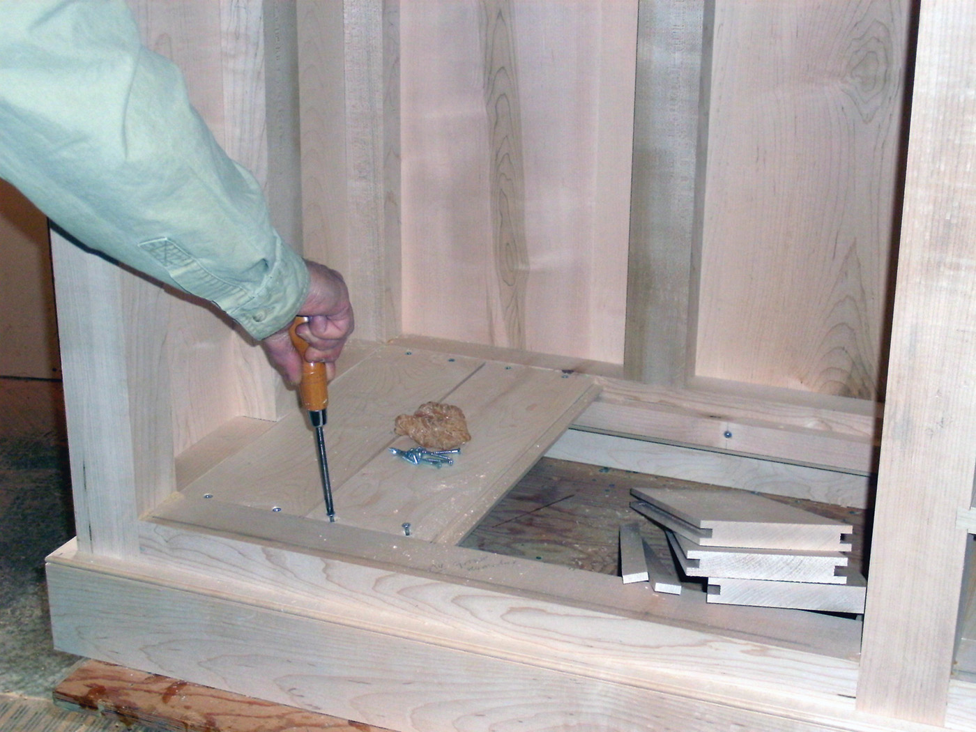
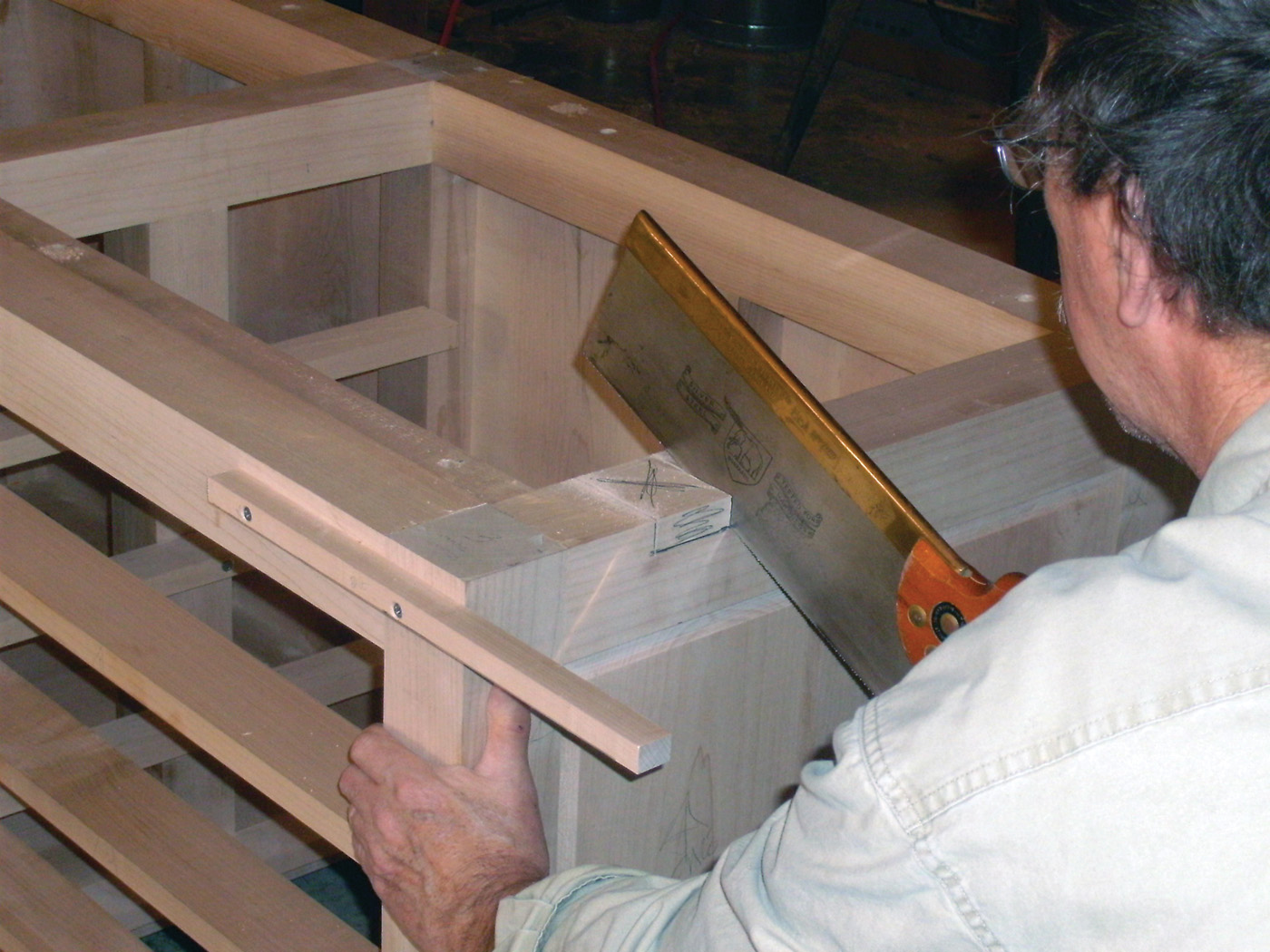
10 The assembled base. Test fit the baseboard and cut it to length.
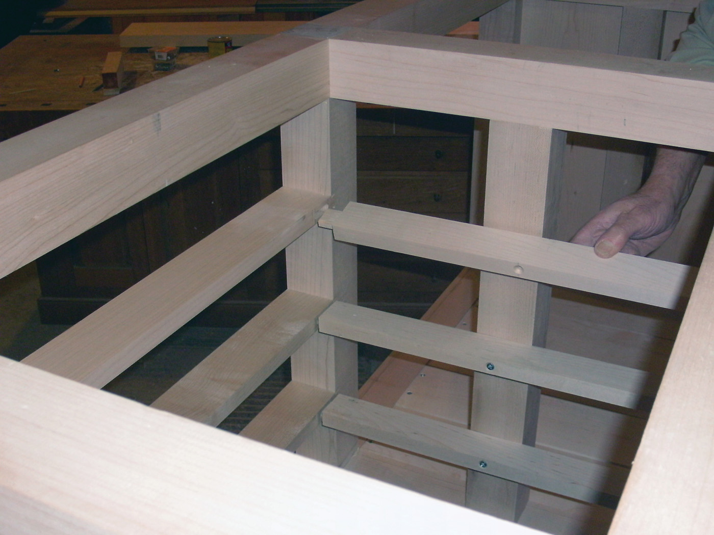
11 The drawer slides are mortised into the dividers.
12 Then they are screwed in place on the interior stiles.
Making the Drawers
The drawer fronts are made of soft maple to match the base. The drawer sides and back are ash. The drawers are 20“ deep and the drawer sides extend 6“ past the drawer back. The extended sides let me pull the drawer out to its full depth without the drawer falling out. The drawer bottoms are cut from 1/2“ plywood. The plywood bottom is rabbeted to form a tongue 1/4“ thick and 5/16“ wide on the front and sides of each drawer bottom. The drawer bottom is glued to the front groove, but left to float freely in the grooves cut on the inside faces of the drawer sides. A slot cut in the back edge of the bottom allows a screw to hold the bottom tight against the back, while allowing for seasonal movement in the panel.

13 The drawers are built with dovetails at the front and a sliding dovetail at the back.
The drawers are dovetailed together: half-blind dovetails at the front and sliding dovetails at the back. The sliding dovetail dado is cut with a 1/2“ diameter dovetail bit set 1/4“ deep. I cut the dovetail on both ends of the back using the same jig I used earlier, repositioning the temporary fence on the jig to locate the cut desired.
To dress up the face of the bench and to make the drawers easier to fit, I used a thumbnail shaped overlapping edge on the drawer fronts. I used a combination of a 3/8“ radius roundover bit and the tablesaw to create the desired shape. I cut the dovetail pins and tails in the front and sides using hand tools.
14 The bottom of the cubby is screwed in place.
Building in Storage Space
The remaining open bay needs only a floor and a pair of doors hung from the legs of the bents on either side of the opening. The floor is simply random widths of maple boards, splined together and loosely laid onto ledger strips screwed to the bottom rails and stretchers.
15 Position the doors and mount them with hinges.
Frame and Panel Doors
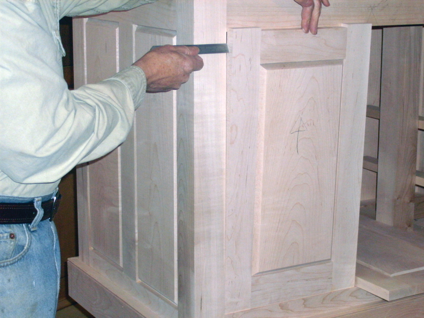
The open bay is enclosed with frame and panel doors inset into the openings. The door frames are joined with pegged mortises and tenons. The rails and stiles are made with 11/8“ thick stock to accommodate the 15/16“ thick panel with the same 45° raised-panel bevel as on the rest of the bench.
The Top
The top is built of 8/4 Hard Maple. Maple boards for the top were passed over the jointer to flat face one wide face, then thickness planed to a thickness of 13/4“. The boards were then jointed, cut to width and glued up to form a top. The top’s ends were trimmed square leaving the rough top 75“ long. To this top were added two 21/2“ thick end caps and a 33/4“ by 33/4“ square laminated front section incorporating square holes for traditional bench dogs. With the added front section and end caps the final dimensions of the bench top is 30“ in width by 80“ in length. A traditional tail-vise was installed on the right hand side of the bench top’s leading edge.
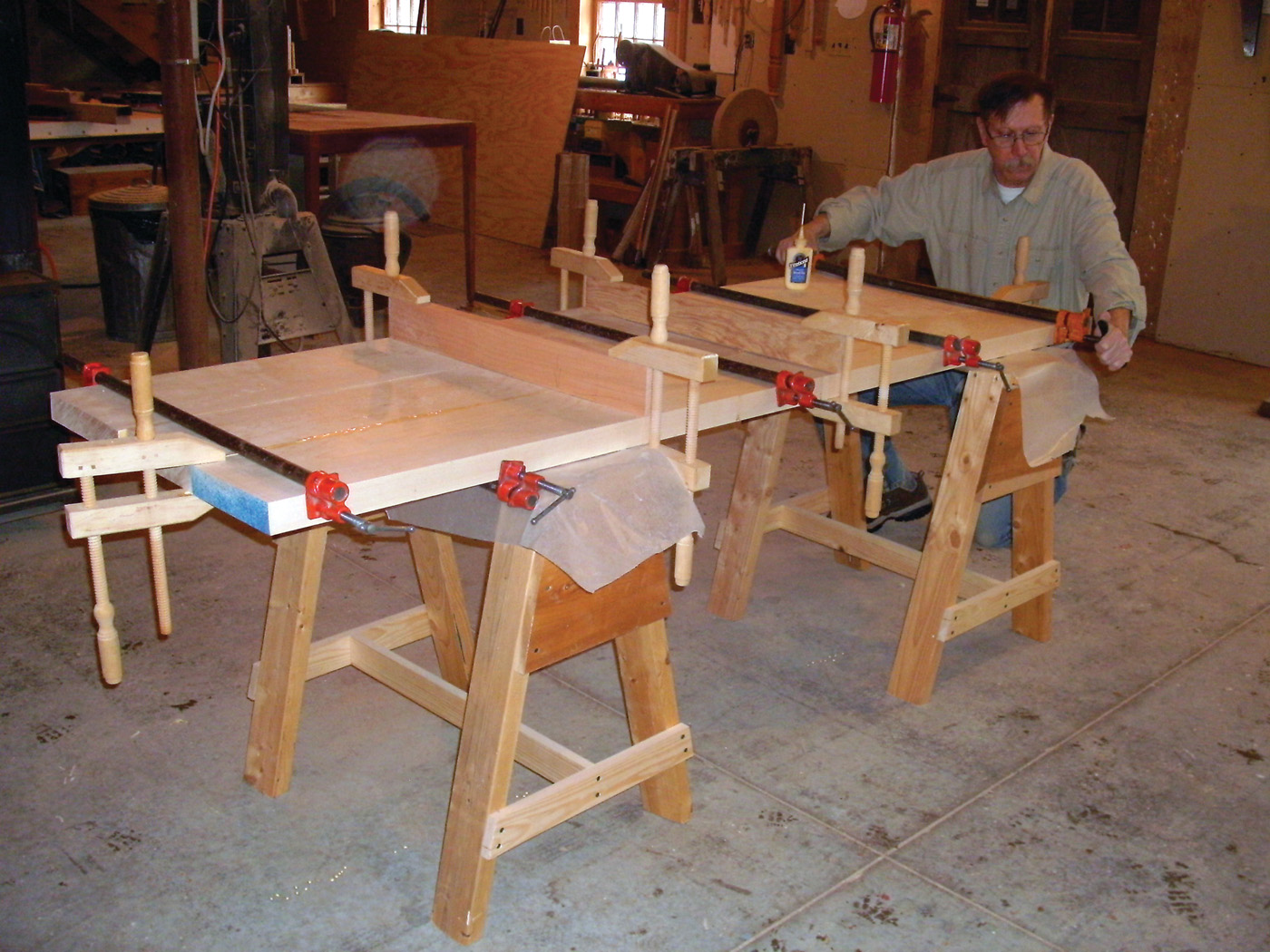
16 The benchtop is glued up from several boards, with cauls to keep it flat.
See American Woodworker Magazine issue 156 for further information on building a laminated bench front with dog holes, and building and installing a tail-vise and end-caps to a bench. A brief overview is highlighted below.

17 The end caps slide over tenons on the bench top.
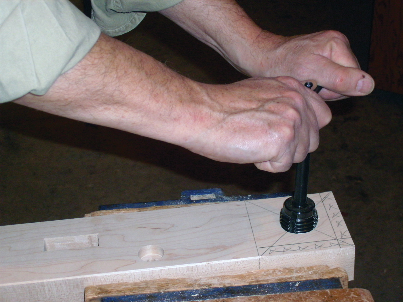
18 The vise hole is tapped with a large wood tap.
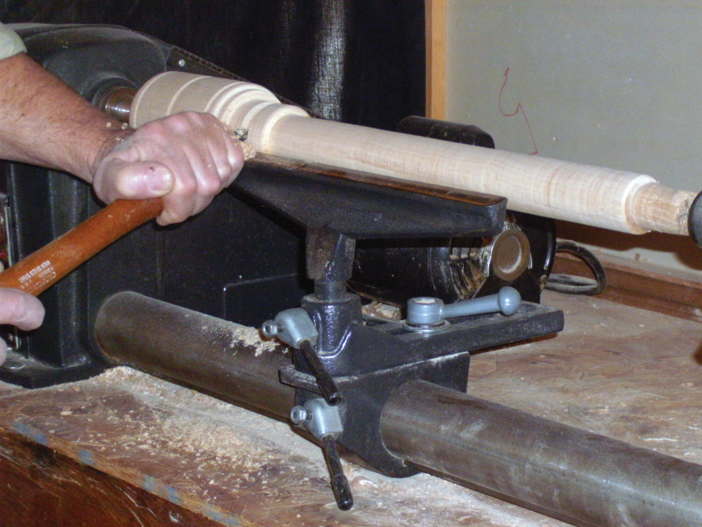
19 Turn the wood screw at the lathe.
20 The stem of the wood screw is tapped with a large wood
tap die.

21 Assemble the dog strip, using spacers for the dog locations.

22 Fit the tail vise in place at the end of the bench. Details for the tail vise construction are available at www.PopularWoodworking.com/OnlineExtras
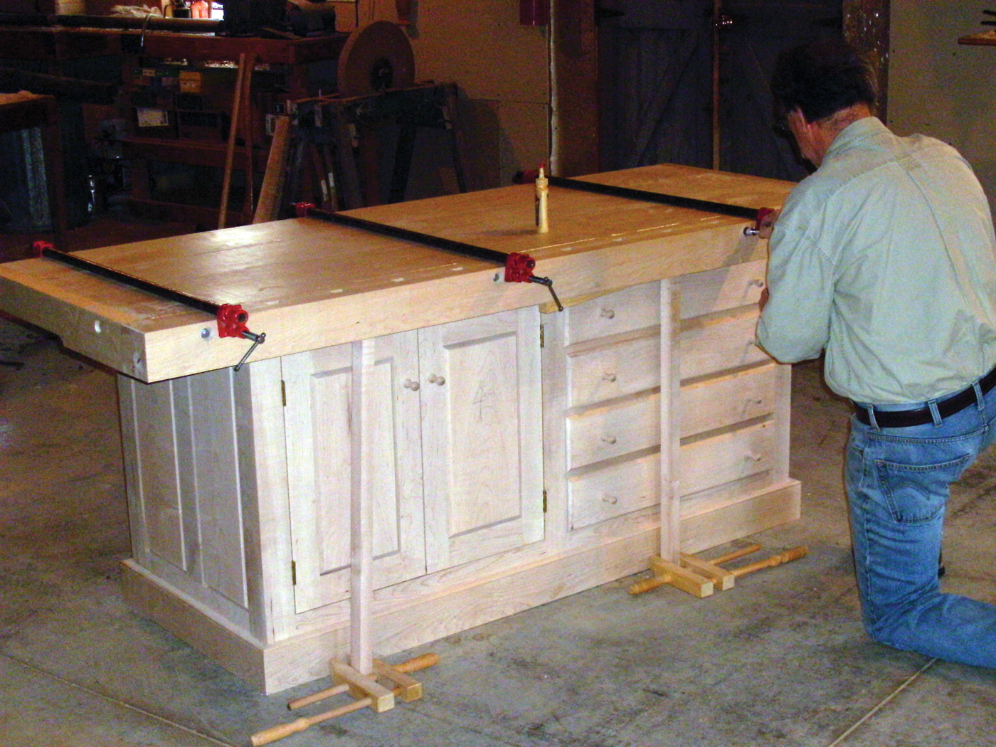
23 Fit the dog strip to the bench surface, while it’s mounted on top of the base. Use supports where necessary to help support the workbench top.

24 Mark the collar of the tail
vise screw.
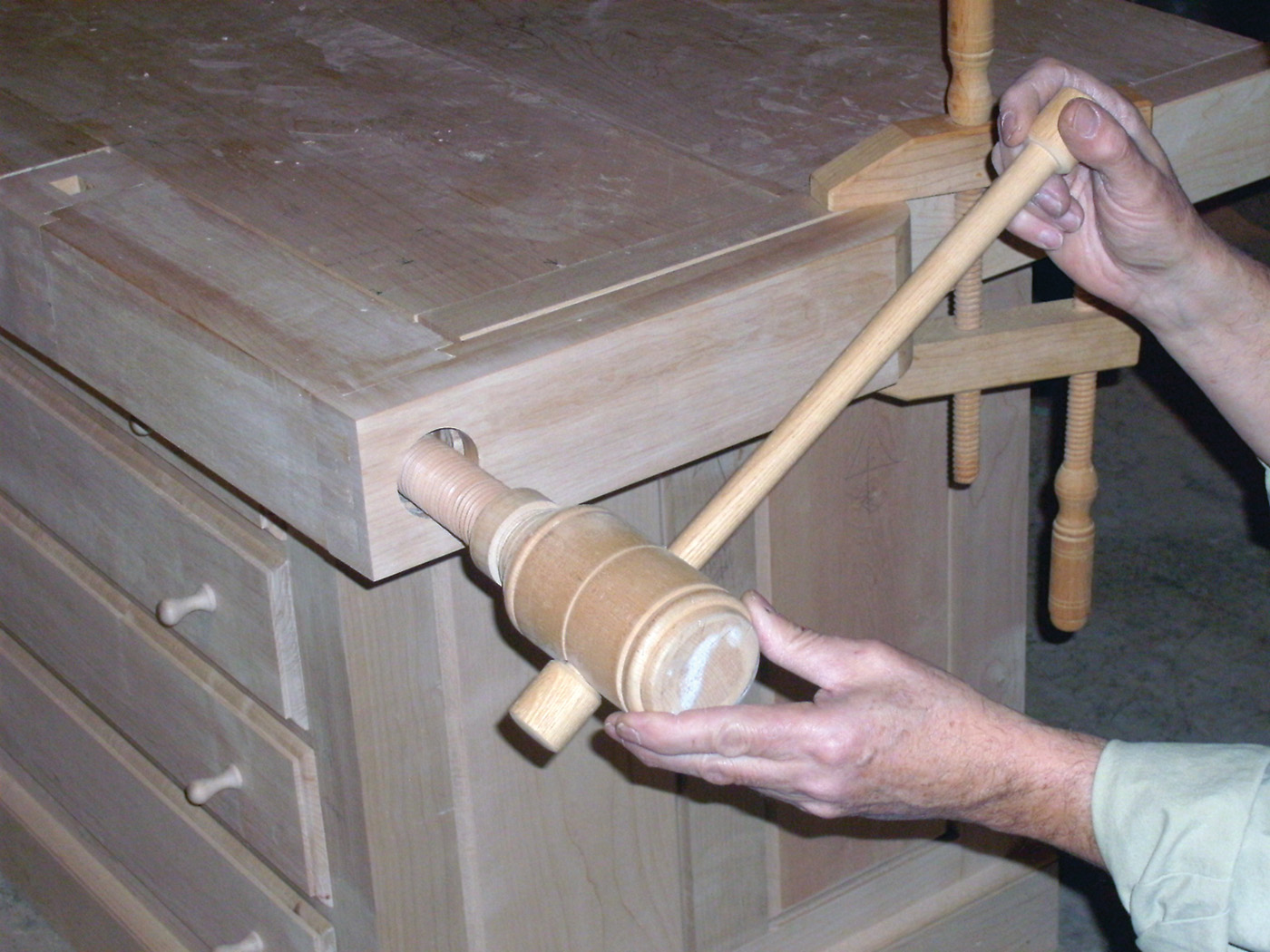
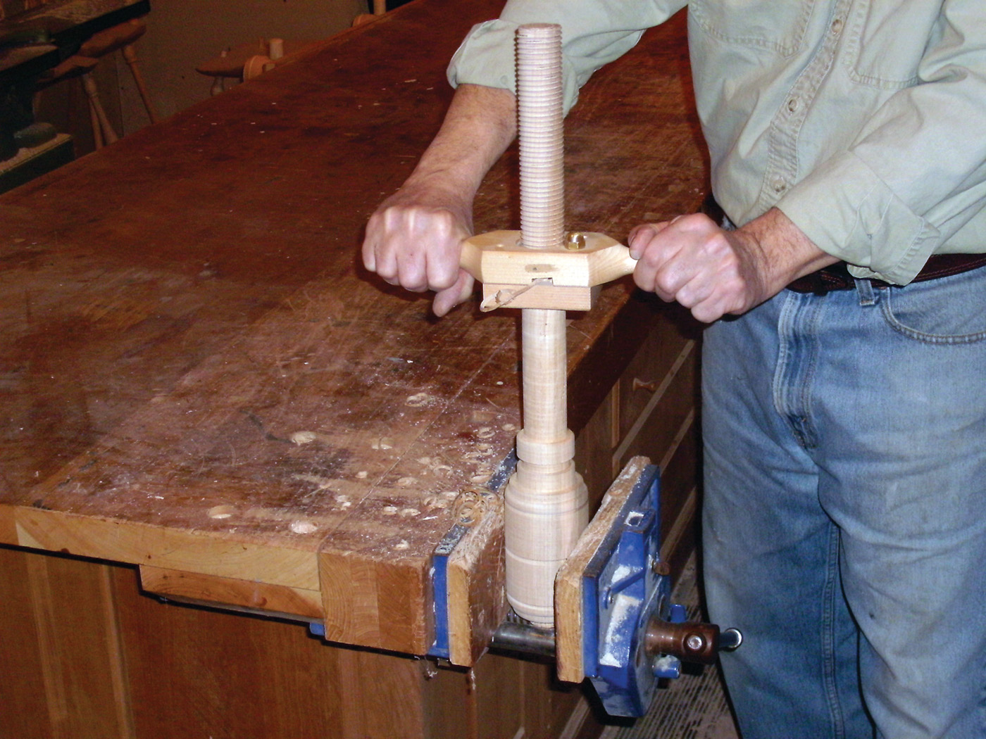
25 Install the tail vise screw by threading it into place.

26 Affix the undercarriage of the tail vise with screws.
27 Notch the bench base to allow the tail vise to move freely when the top is attached.
The finishing touch is the 4“ wide baseboard I wrapped around the bench’s base. I routed a 3/8“ wide decorative bead on the top edge of the base board stock, then cut and mitered the base board stock to fit the base. The base boards was screwed in place and the screw holes plugged.