We may receive a commission when you use our affiliate links. However, this does not impact our recommendations.
A word about Plywood
I used 3/4″ thick Baltic Birch for this cabinet. It has a thicker, more durable veneer than typical plywood. Like all plywood, however, 3/4″ doesn’t mean 3/4″. For example, Baltic Birch is typically 11/16″ thick. Whatever plywood you use, check its thickness and adjust your dimensions accordingly. Also, Baltic Birch comes in 5′ x 5′ sheets; that dimension is accurate, meaning it’s 60″ both ways with no extra.
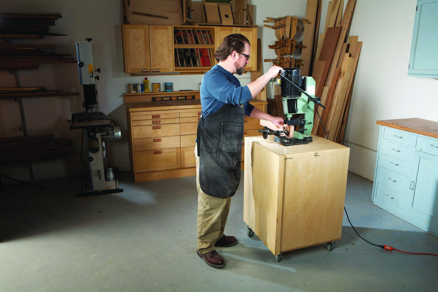
Benchtop mortisers are handy tools to have in your kit, but they’re typically not used frequently. That means they’re usually stored when not in use. So when you need to use your mortiser, it involves lifting and carrying that heavy bugger to your bench and then back to storage when you’re done. With this self-storing mortiser cabinet, the machine is mounted to a thick platform that rotates a steel pivot rod. When you want to use the tool, swing it up and lock it in position. When you’re done, swing it back down.
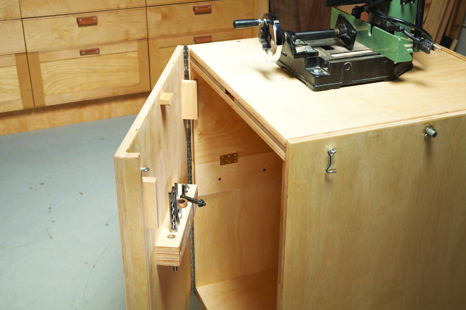
The door is the key to keeping the cabinet and rotating platform secure and steady for use. When the door is closed, two support locks prevent the platform supports from tipping. A locking tab slips into a mortise in the platform’s edge making the platform rock solid. Since the cabinet’s sides are not connected at the upper front corners, I added a lip to the door to keep the cabinet sides square. All of these mechanisms are engaged by closing the door, and a simple door latch prevents the door from opening.
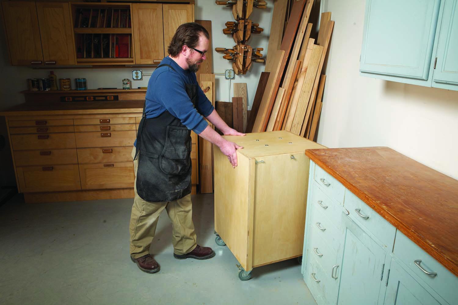
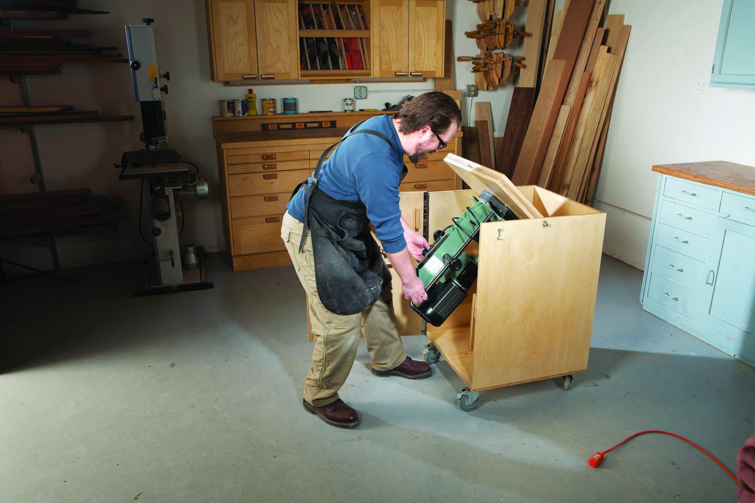
When you’re done with your mortising tasks, just swing the machine back into the cabinet. Closing and latching the door engages the platform lock with the platform, preventing the mortiser from swinging inside the cabinet while you’re wheeling it around. It also keeps the platform level so you can set stuff on it. An extra horizontal surface never goes to waste!
Size the cabinet
Benchtop mortisers are similar in size, but you’ll need to do the math first to make sure yours will fit this cabinet. If it doesn’t, you’ll have to adjust some dimensions. I’ll walk you through the steps of how I dimensioned this cabinet.
First, determine how much space is needed on each side of your mortiser, taking into account handles, fences, etc. that protrude beyond the base’s footprint. Second, measure your mortiser’s height and add 2″ – 3″. This is how much vertical space you need inside the cabinet.
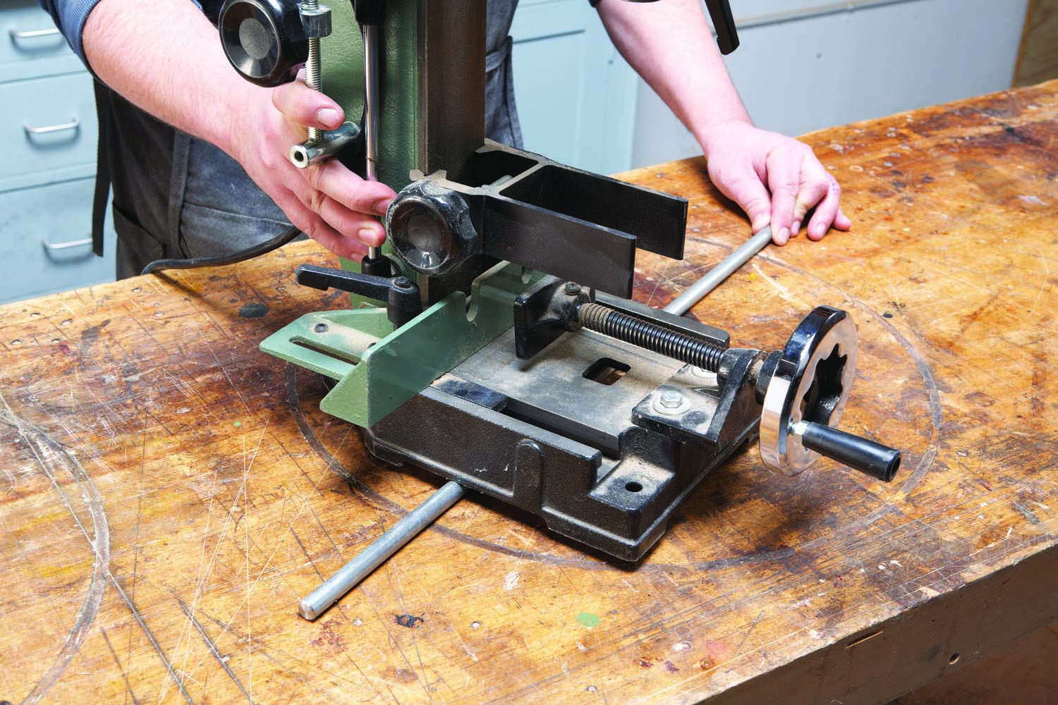
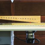
Photo 1. Find your mortiser’s balance point. Place the pivot rod under the tool’s base and carefully roll the mortiser back and forth until it balances on the pivot rod.
Lastly, find your mortiser’s balance point (it’s likely not the center of the base). Mounting the mortiser with its balance point over the pivot rod makes it easier to rotate. To find the balance point, set your machine on the pivot rod and roll it back and forth until it almost balances on the rod (Photo 1). It’s unlikely that you’ll get it to balance perfectly, but close is good enough. Make a note of the distance from the base’s front edge to the balance point.
Once you’ve found the tool’s balance point, you can determine the cabinet’s depth. When the tool is in the “in use” position, you’ll want it closer to the front of the cabinet for ease of use. Figure out how close you want the base’s front edge to the cabinet’s front. Add this dimension to the distance from the base’s front edge to the balance point and then double it. For example, if the balance point is 5″ back from the front edge of the base, and you want the front edge of the base 5″ back from the cabinet’s front, that gives you a total of 10″. So your platform would be 20″ deep. The reason you have to double the measurement is that the pivot rod must be mounted in the center of the cabinet.
Make the platform
The platform assembly needs to be beefy to support the weight of the tool. I used two layers of 3/4″ Baltic birch for the platform’s outer layers (A), and 1/2″ mdf for the core (B). The reason I chose mdf instead of plywood for the core is that the pivot rod is exactly 1/2″ in diameter, and 1/2″ Baltic birch plywood is slightly under 1/2″. MDF is a full 1/2″. I used glue and brad nails to assemble the platform parts.
Make the core in two pieces leaving a 1/2″ gap for the pivot rod. Before attaching the core pieces to the plywood, make a 1″ deep x 2″ wide cutout on one long side of each core piece. When the platform is assembled, the cutouts form mortises for the locking tabs.
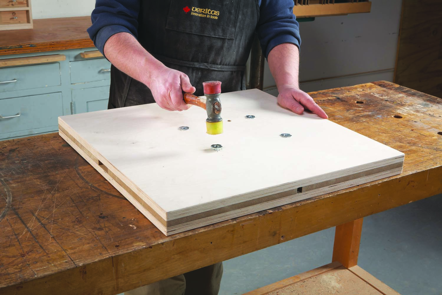
Photo 2. Assemble the tool platform and install tee-nuts in the underside. As the bolts and tee-nuts support the mortiser’s weight when it’s stored, use the largest bolts that your tool’s base will allow.
Attach one core half to one of the platform pieces. Place the pivot rod in position, slide the second core half against it, and then glue it in place. Attach the second platform piece.
Mark for your tool’s mounting holes and use your drill press to drill all the way through the platform. Install tee-nuts in the bottom face of the platform (Photo 2). Use the largest bolts and tee-nuts that your tool’s base will accommodate.
Build the cabinet
Before assembling the cabinet (Fig. 01), there are a couple pre-assembly steps. First, the sides (C) need to be drilled for the flanged bearings in which the pivot rod turns. These bearings are oil-impregnated bronze, so they never need lubrication. Since the bearings are flanged, they require a stepped hole. To determine the holes’ placement, find the center of the platform’s thickness. Measure that distance from the top edge of each side to locate the holes’ vertical placement (Fig. 02). Center the hole on the sides’ depth minus the back.
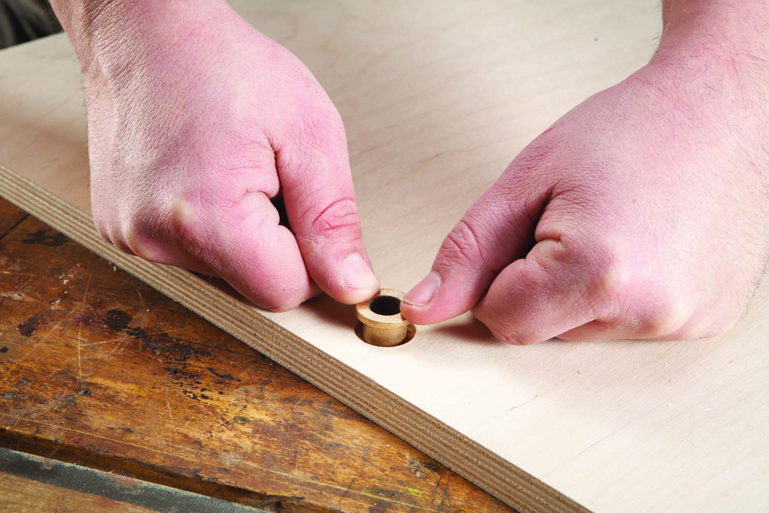
Photo 3. Drill a stepped hole to house the bushing in which the pivot rod rotates. Press the pushing into the hole. This is an oil impregnated bronze bushing that never needs lubrication.
Use a Forstner bit to drill a 7/8″ dia. x 1/8″ deep recess. Next, drill a 5/8″ dia. through hole centered in the 7/8″ recess (Fig. 02). Press the bearings into the stepped holes (Photo 3).
Glue up the bottom assembly. The bottom (D) is smaller than the sub-bottom (E), forming for a rabbet equal to your material’s thickness at the assembly’s back and both sides.
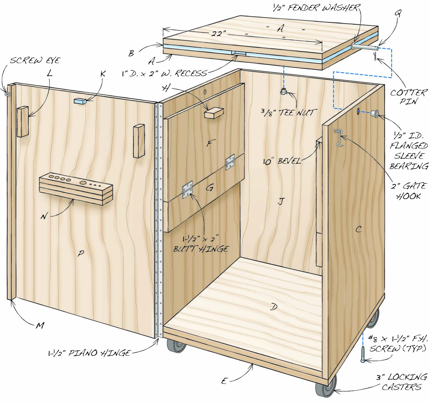
Fig. 01. Exploded View
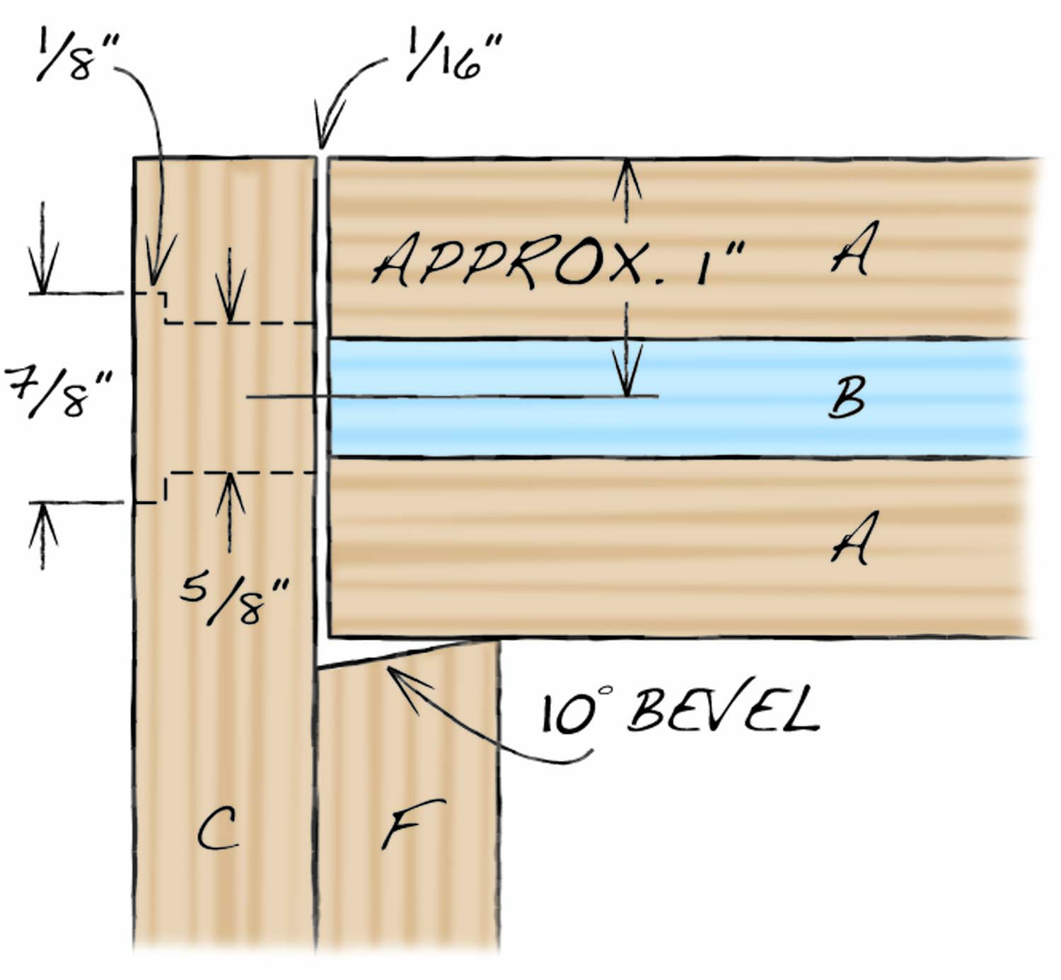
Fig. 02. Bushing Hole Detail
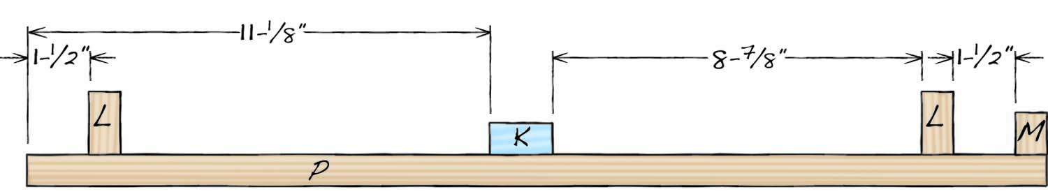
Fig. 03. Door Detail
Cutting List
| Overall Dimensions: 34″ H x 24-1/2″ W x 24-1/2″ D | ||||
| PART | NAME | QTY | MATERIAL | Th X W X L |
| A | Platform | 2 | Baltic birch | 3/4″ x 22″ x 22-7/8″ |
| B | Platform core | 2 | mdf | 1/2″ x 22″ x 11-3/16″ |
| C | Side | 2 | Baltic birch | 3/4″ x 23-11/16″ x 30-1/4″ |
| D | Bottom | 1 | Baltic birch | 3/4″ x 23″ x 22-1/4″ |
| E | Sub-bottom | 1 | Baltic birch | 3/4″ x 23-5/8″ x 23-5/8″ |
| F | Support | 2 | Baltic birch | 3/4″ x 11″ x 22-3/4″ |
| G | Support cleat | 2 | Baltic birch | 3/4″ x 4″ x 23″ |
| H | Support pull | 2 | Baltic birch | 3/4″ x 1-1/2″ x 3″ |
| J | Back | 1 | Baltic birch | 3/4″ x 22-1/4 X 30-1/4″ |
| K | Platform lock | 1 | mdf | 1/2″ x 3/4″ x 1-1/2″ |
| L | Support lock | 2 | Baltic birch | 3/4″ x 1-1/2″ x 4″ |
| M | Door lip | 1 | Baltic birch | 3/4″ x 1″ x 31″ |
| N | Storage block | 3 | Baltic birch | 3/4″ x 2″ x 11″ (a) |
| P | Door | 1 | Baltic birch | 3/4″ x 24-1/4″ x 31″ |
| Notes: | ||||
| (a) Glue up three thicknesses of 3/4″ Baltic birch. Size to suit. | ||||
Cut the supports (F) and support cleats (G). The upper edge of each support is beveled at 10°. When the supports are flipped up, the bevel’s point is the only part that touches the platform. Glue and screw the support pulls (H) to the supports.
Photo 4. Slide the pivot rod through the platform and bushing to get the correct placement for attaching the hinged support assemblies to the cabinet’s sides.
Attach the supports to the support cleats using butt hinges. Lay one of the sides flat on your bench. Slide the pivot rod through the platform and into the side’s bushing. Make sure the platform is flush with the side’s top edge. With the platform is in its finished position, set the support assembly in place and glue and screw it to the side (Photo 4). Repeat this process for the other side.
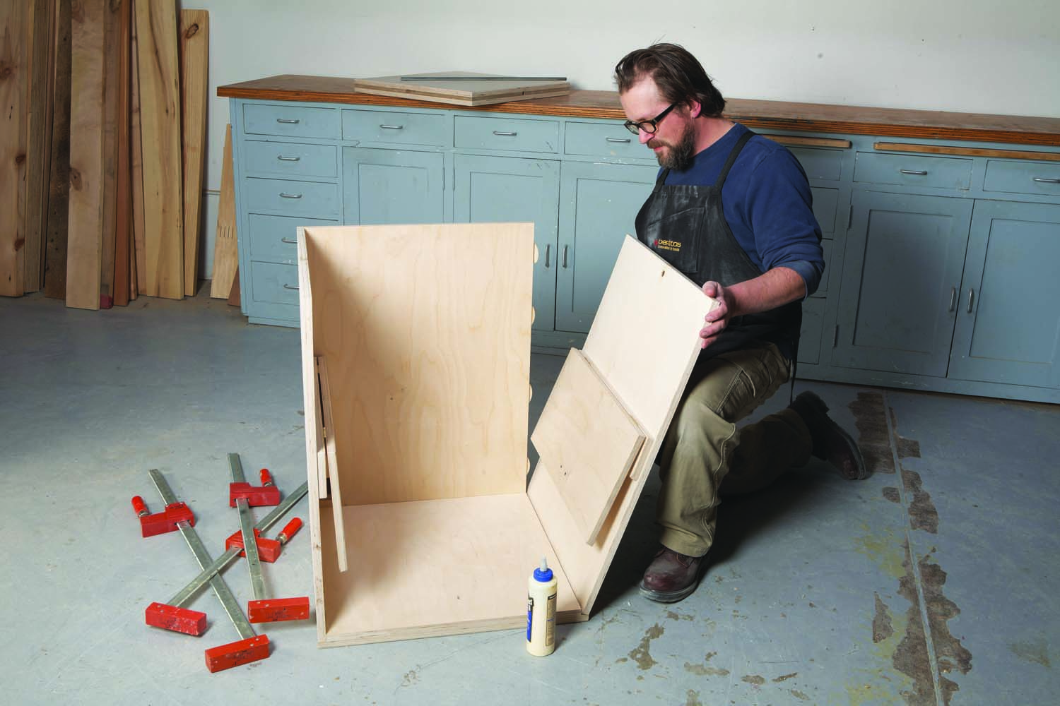
Photo 5. Fasten the sides and back to the bottom assembly. I used #20 biscuits to assemble the back and sides, and glue and screws to attach the bottom assembly.
Assemble the back (J) and sides using #20 biscuits, glue and clamps (Photo 5). Use the bottom assembly as a template to keep the glue-up square. When the glue is dry, glue and screw the back and sides to the bottom assembly.
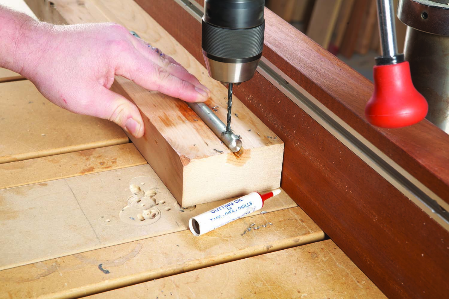
Photo 6. Drill a 1/8″ dia. hole through each end of the pivot rod for the cotter keys. The distance between these holes must be the exact width of the cabinet.
On your drill press, use a V-block to drill a 1/8″ hole in each end of the pivot rod (Photo 6). Make sure the distance between the holes is the exact total width of the cabinet. Since this cabinet has nothing connecting the front upper corners, the cotter keys installed in these holes help to keep the cabinet square.
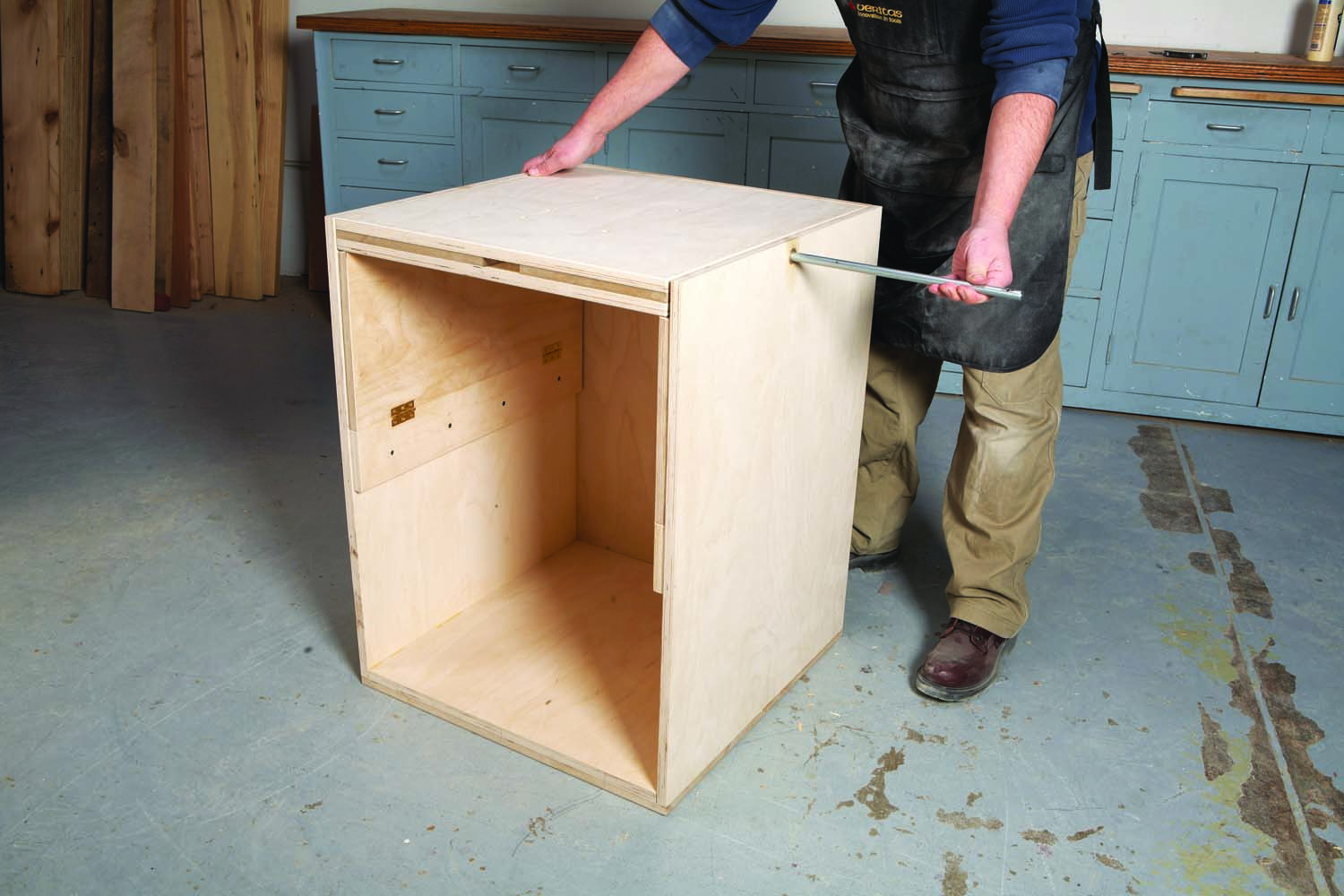
Photo 7. Set the platform on the supports and slide the pivot rod through the bushings and platform. Insert 1/2″ i.d. fender washers between the platform and the cabinet’s sides. Insert the cotter keys in both ends of the pivot rod.
To install the platform, flip up both supports and set the platform in place. Slide the pivot rod through the platform (Photo 7) with a 1/2″ fender washer between each side and the platform. Install the cotter keys to secure the rod.
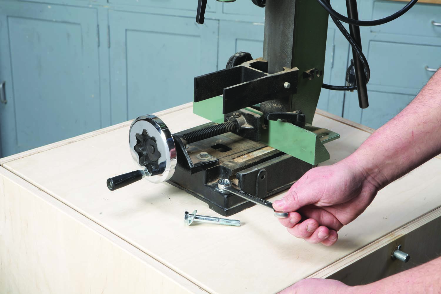
Photo 8. Mount the casters and the door, and then bolt the machine to the platform.
Mount the platform lock (K), support locks (L), door lip (M) and storage block (N) to the door (P, Fig. 03). Mount the door to the cabinet using a piano hinge or butt hinges, and then install the latch. Lastly, mount locking casters to the bottom and bolt your machine to the platform (Photo 8). Apply whatever finish you prefer.
Here are some supplies and tools we find essential in our everyday work around the shop. We may receive a commission from sales referred by our links; however, we have carefully selected these products for their usefulness and quality.