We may receive a commission when you use our affiliate links. However, this does not impact our recommendations.

Next-Generation Router Table
Make more accurate cuts with a flat, solid-surface top.
By John English
9 Key Features1. Hinged Top. Bit changes are much easier. 2. Pivot Control. Just loosen the fence’s left side for quick micro-adjustment. 3. Tall Fence. There’s plenty of support for raised panel work 4. Solid-Surface Top. It’s slick, flat and durable. 5. Fence T-slots. Attach a light, stops and feather-boards. 6. Huge Work Surface. It’s 26” x 43”. 7. Double Dust Collection. There are ports top and bottom. 8. Custom Sized Bit Opening. Make it any diameter you need. 9. Storage. There’s lot’s of room for bits, routers and accessories. This router table took thirty years to build. No kidding. I don’t mean that it took me thirty years to actually make it, but it took me that long to figure out how to do it right. I’ve used a lot of router tables over those years, and all have come up short. I’ve been frustrated with complicated fence locks, panels tipping because the fence wasn’t tall enough, insert plates that were finicky to level, small worktops that don’t support a door or drawer, inadequate dust collection, bad lighting, and on top of all that, having to kneel on the floor to change the depth of cut. After all those disappointments, I finally built a router table that solved all these problems. Build The Case1. Glue two pieces of hardwood to create the four legs (A). Plane all four faces of each leg, and then trim them to length. Using a dado set or a router equipped with a straight bit and a fence, mill a stopped groove in two adjacent faces of each back leg and one face of each front leg (Fig. A). These grooves receive the side and back panels. Note that the front legs are not grooved to receive the face frame. Square the end of each groove with a chisel. 2. Clamp the four legs together and locate the screw holes in each groove. On the drill press, use a 3/32″ bit to drill pilot holes through the legs. Counterbore the exit holes for plugs, using a 3/8″ Forstner bit. 3. Cut the sides (B) and the back panel (C). Screw and glue the two back legs to the panel. Screw and glue the side panels to the back legs, then attach the two front legs. Keep the panels flush with the tops of the legs. Glue plugs in the legs to cover the screw holes. 4. Mark the locations of the two divider panels (J) on the inside face of the back panel (Fig. A). Drill five equally-spaced pilot holes along the center of each location. Cut the divider panels to size, and then glue and screw them to the back panel using screws driven through pre-drilled, countersunk pilot holes. Clamp the panels in place as you drive the screws. 5. Make the side stiles (D) and the top and bottom rails (E and F) of the cabinet’s face frame. Drill and countersink pilot holes at the joints, then glue and screw the pieces together. Glue and screw the face frame between the front legs. Cut the two middle stiles (G) to size and install them with glue and finish nails (Photo 1). Run a couple of screws up through the bottom rail into the end of each stile. 6. Cut the sub-top (K) to size and install it with glue and thirty-two screws driven into the top edges of the sides, back and divider panels, and the top rail of the face frame (Photo 2). Pre-drill for the screws and countersink the heads. 7. Mark the opening in the top (Fig. C) and clamp four cleats to the cabinet to act as guides for your router (Photo 3). Their locations will depend on the size and shape of your router base. Chuck a 3/8″ straight bit in the router and plunge through the top in four or five incremental passes in order to remove the waste from the opening. Glue and nail trim (L) to all four edges of the sub-top, mitering the corners. Screw and glue cleats (M and N) around the bottom edges of each of the two side compartments. Cut the two compartment bottoms (P) to size. Notch one back corner of each using the bandsaw so they fit around the cabinet legs, and install them with screws driven up through the cleats into pre-drilled, countersunk holes. The doors (Q) are simply birch-veneered plywood panels with edge trim (R) that is mitered to length and applied with glue and finish nails. Install them with surface-mounted, self-closing hinges. Use a couple of drawer pulls for handles. Prepare The Top8. On the tablesaw, cut Corian or Avonite solid surface material for the top (S) to 26″ x 43″ and belt sand the edges. Apply masking tape in the general vicinity of the pivot hole (Fig. B), and then mark the hole’s exact location on the tape. Drill the hole. Make a trammel for your router by fastening the router to some 1/2″-thick hardwood or plywood stock that’s at least 4″ wide and 4 ft. long. Chuck a 1/2″ dia. straight bit in the router. At the pivot end of the trammel, drill a 1/4″ dia. hole 41-3/4″ from the center of the bit. Loosely attach the end of the trammel to the top with a 1/4″ bolt, two washers and a hand-tightened nut, and cut an arc across the left end of the top in several 1/8″ deep passes (Photo 4). Once you’ve cut all the way through, gently sand all the top’s edges. 9. Place the top on the cabinet flush with the back. The top’s right edge (where the pivot hole is located) should overhang the cabinet by 2″. Temporarily clamp the top in place and mark the cabinet’s outline (Photo 5). Also mark the large, rectangular hole in the sub-top. Cut two stiles (T) and four rails (U) for the support frame (Photo 6). The inner rails should line up with the edges of the large hole in the sub-top. Assemble the support frame with biscuits and glue and attach it to the underside of the top with clear silicone adhesive. Apply weight (a sandbag works well) while the silicone cures. An overnight cure is good, but it’s better to let it cure for a few days. 10. Connect the top and support-frame assembly to the cabinet with a continuous (piano) hinge. Use longer 1-5/8″ bugle screws in the center and one near each end for strength. The Top’s Lift Support11. When raised, the top is locked in the open position by a three-part mechanism: an arm with both top and bottom cleats (Photo 7). Make the top cleat (V, Fig. D). Attach it to the inside edge of the support frame’s left-hand rail, using two screws and glue. 12. Make the bottom cleat (W). Cut it to size and then miter one end. Bore three holes for carriage bolts. Epoxy a bolt into the middle hole. Use a washer and nut to pull the bolt tight while the epoxy cures, and then locate the bottom cleat in the cabinet. Drill holes in the partition for the other two bolts, and install the cleat with washers and nuts. 13. Make the arm (X) and install it with two plastic tri-knobs. Mount the Router14. With the top closed, drill a 3/4″ dia. hole where the center of the router will be located (Fig. B). Lock the top in the open position and use the hole to locate your router’s baseplate on the underside (Photo 8). Mark and drill holes for mounting bolts using the baseplate as a pattern. Close the top and countersink the holes. Install the router base, minus the baseplate, with stove bolts, washers and nuts. 15. Take a look at your router bit collection and decide how large you would like the hole in the top to be. (At my woodworking school, I strongly recommend limiting router bits to 2″ dia.) To enlarge the hole, begin by using a rabbeting bit with a guide bearing that is slightly smaller than the hole (Photo 9). Follow up with a bearing-guided pattern bit, and then use these bits in sequence until the hole is as large as you wish. Make a final pass with the rabbeting bit to leave a ledge that will support hardwood inserts (Photo 10). Build The Fence16. Cut the fence base (F1) to size and use a miter saw to trim the pivot end at an angle (Fig. H). Drill the pivot hole at the location indicated. Lay the fence base on the top and secure the pivoting end with a bolt, two washers and a nut that is just finger tight. Mark the opposite end (Photo 11), then cut the base 2″ longer than the top, using the offcut from the top as a guide to make a curved end. Mark and cut the circular bit opening in the fence base, then pre-drill some screw holes for assembling the frame (Photo 12). 17. Cut the fence back wall (F2) to size and bandsaw the opening in it for a dust collection port (Fig. H). Align the back wall along the front edge of the base and attach it with glue and screws. Cut the front wall (F3) to size. Cut the sliding fences (F4 and F5) to size and mill one T-slot in each (Photo 13 and Fig. G). (It helps to mill each groove with a 1/4″ straight bit first, and finish the cut with the T-slot bit.) Cut the top molding (F6) to size and plow a T-slot in that, also. Glue and clamp the front and back walls together. When the glue has dried, trim the top molding to length with a short 45° miter on each end (that is, leave about 1/3 square and miter the rest), and then attach it with glue and clamps. Cut the four fence braces (F7) to size and shape, and install each with glue and screws. Drill four holes for the T-bolts that lock the sliding fences in place. 18. Build the fence-clamping block (Photo 14 and Fig. E). Nibble a small dado on the bottom section (F9), and install a T-bolt before gluing both sections together (Photo 15). Attach a self-adhesive felt chair pad to the top of the lock, then add a little sandpaper or grip tape to the top of the rabbet. Mark and drill a hole in the fence base to align with the T-bolt, and install the lock with a tri-knob (Photo 16). Screw the dust port in place behind the fence and you’re ready to add some handy accessories. Source(Note: Product availability and costs are subject to change since original publication date.) Peachtree Woodworking Supply, ptreeusa.com, 888-512-9069, Right Angle Dust Port, #386; 12″ x 12″ Dust Hood, #430; Safety Power Tool Switch, #1043; Small Router Bit Guard, #1049. Cutting List
Fig. A: Exploded View
Fig. B: Frame and Top
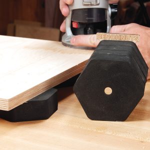
Fig. C: Sub-top
Fig. D: Support Arm
Fig. E: Clamping Block
Fig. F: Featherboard
Fig. G: End View of Fence
Fig. H: Top View of Fence
This story originally appeared in American Woodworker February/March 2009, issue #140.
|
Click on any image to view a larger version.
1. Begin building the router table by making the base. Construction is quite simple, using just screws, glue, and a nailed-on face frame in front.
2. Attach a plywood sub-top to the base. The subtop prevents the base from racking. It also supports the working top which is made from 1/2″ thick solid-surface material, such as Corian or Avonite.
3. Rout a rectangular hole in the center of the sub-top. Make a series of shallow passes until you’ve cut all the way through. Place the solid surface top on the sub-top.
4. Rout an arc on one end of the solid-surface top using a trammel fastened to the router’s base.
5. Clamp the top to the base and trace all the way around the top’s underside. Turn the top over.
6. Build a frame to fit inside the rectangle you drew. Glue the frame to the top using silicone adhesive. Attach the top assembly to the case with a continuous hinge.
7. Build an arm to prop the top. This makes it much easier to change bits because there will be plenty of elbowroom around the router. Plus, you don’t have to bend over.
8. Drill a 3/4″ dia. hole through the top, then remove the router’s baseplate and mark the locations of its mounting holes onto the top. Drill the holes and lower the top.
9. Enlarge the opening by using a series of rabbeting bits and pattern bits. A rabbeting bit leaves a ledge around the hole making it perfect for fitting an insert.
10. Make a set of wooden zero-clearance inserts to fit the hole. Drill variously sized holes in the inserts to fit your bits.
11. Mark the length of the fence’s bottom board. Cut the board 2″ longer than the top.
12. Drill pilot holes in the fence using a drill press. This ensures that all the pieces of the fence are square when they’re assembled.
13. Cut T-slots in the fence’s face pieces. This can’t be done on a tablesaw, but you could borrow a friend’s router table or use a handheld router and an edge guide.
14. Make the fence’s clamping block. It contains a T-bolt that’s trapped between two pieces of wood that are glued together. Attach a felt chair pad as a spacer.
15. Drill a hole through the fence for the clamping block’s T-bolt.
16. Attach the clamping block to the fence with a plastic knob. To adjust the distance from any router bit to the face of the fence, loosen the knob and pivot the fence back and forth. Accessories
Featherboard: Make one or two adjustable featherboards to fit the fence’s T-slots (Fig. F). A featherboard increases the accuracy and consistency of your cut by holding your workpiece firmly down on the tabletop.
Switch: Add an aftermarket switch to the table to make it easier to turn the router on and off (see Source, below left). If you’re right-handed, mount the switch on the right side of the cabinet, near the front and up high.
Dust Hood: Install a 12″ plastic dust hood to keep dust away from your router’s motor. Mount the hood on a plywood frame attached to cleats. The gap between the bottom of the router and the hood should be about 2″.
Fence Position Ruler: Epoxy a 12″ metal ruler into the top for
Lamp Support: Good light is always an issue, isn’t it? You
Guard: Protect your fingers by covering the bit with an adjustable plastic shield that fits in the fence’s T-slot (see Source, above left). |