We may receive a commission when you use our affiliate links. However, this does not impact our recommendations.
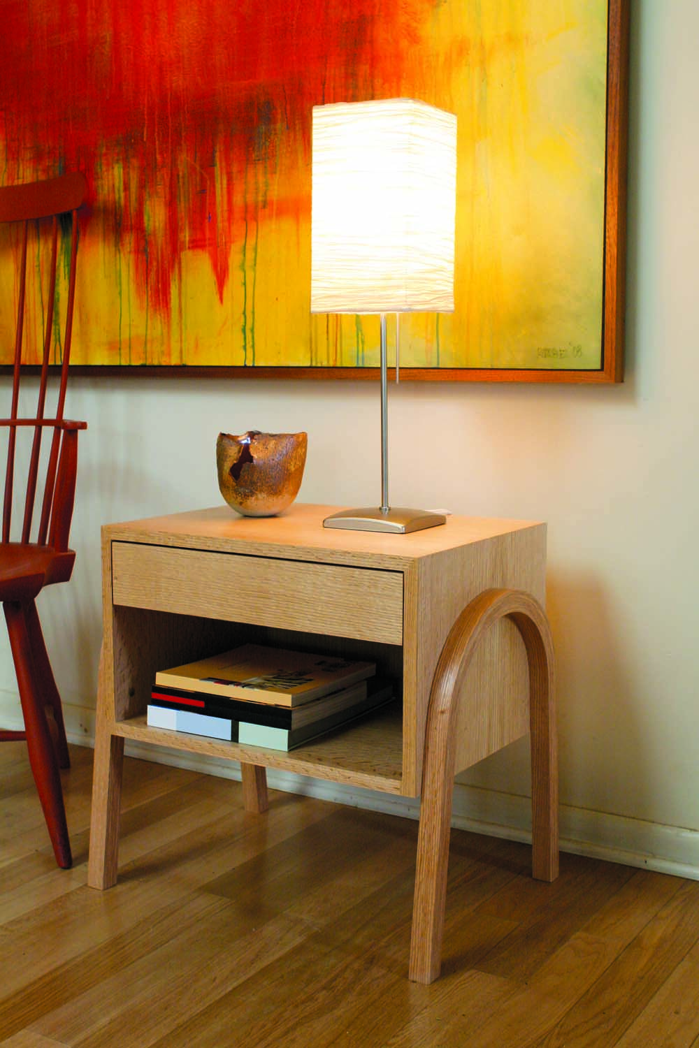 Back in the 1950s, traditional cabinetmakers in Scandinavian workshops produced sleek, powerful furniture using modern materials and modest machines. This project pays homage to those exciting days of Mid-century modern furniture.
I designed the Metropolitan Console to function as an end table or a nightstand. Its low profile, streamlined design and light color fits well in small rooms and tight spaces.
The cabinet is made from riftsawn red oak plywood. The orderly parallel lines of riftsawn wood are perfect for this style, which sought a clean break from the clutter of old-fashioned design.
You’ll Learn How To:
Make a plywood case with mitered corners …
Glue up laminated legs…
And install a side-hung drawer.
Prepare the Plywood
The case is a simple plywood box with a twist: The wood’s grain runs seamlessly around the top and sides, as if it were wrapping paper. It’s a neat trick.
The secret to pulling this off is to crosscut cut the sides (A), top and bottom (B) in consecutive order from one sheet of plywood. You’ll miter the ends of each piece, then assemble them like a folded cardboard box (Fig. 01).
Begin by cutting a long piece of plywood (Fig. 07). (Cut another piece about 15″ square from the same sheet for test cuts.) Draw crosscut lines as shown in the diagram. Write the name of each piece on its front edge, and, for insurance, draw a triangle and a circle across the side and top pieces. These marks will help you reassemble the pieces in the same order later on.
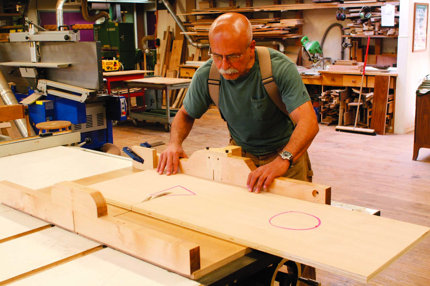
Photo 1. Cut the plywood parts all in a row, from one long sheet. Later on, you’ll arrange the pieces so the grain flows seamlessly all around the console.
Here’s how to make a minimum number of cuts, so the grain matches as closely as possible from one piece to the next. Begin by cutting off the bottom piece, including the 1″ waste shown on the left side of the diagram. On the piece that remains, cut off the 1″ waste shown on the right side of the diagram. Cut off both side pieces using a stop block to ensure that they are the same length (Photo 1). The top piece will remain; trim the bottom piece to match the length of the top.
Cut a rabbet to receive the back (C) along the rear edges of all four pieces.
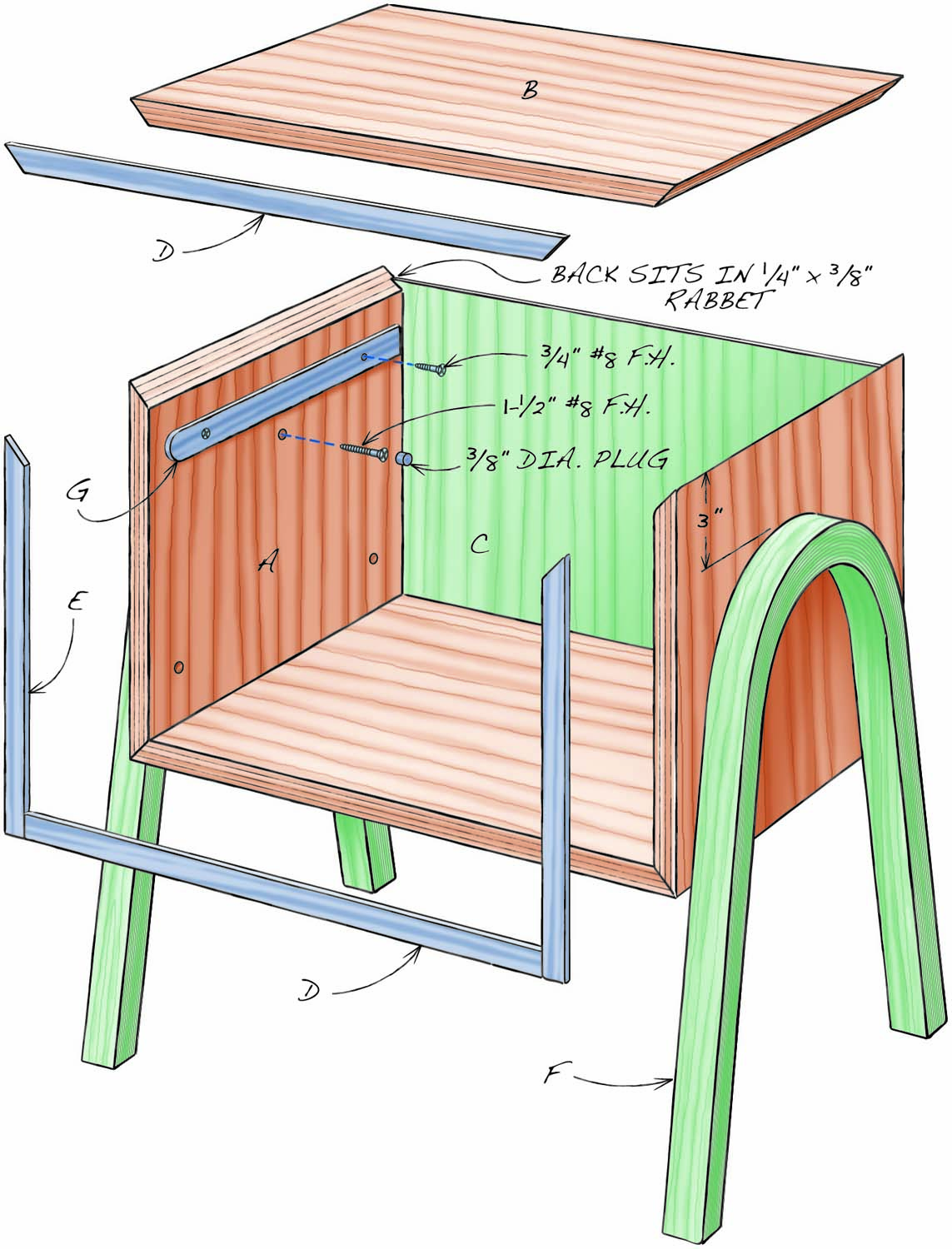
Fig. 01. Exploded View (does not include drawer)
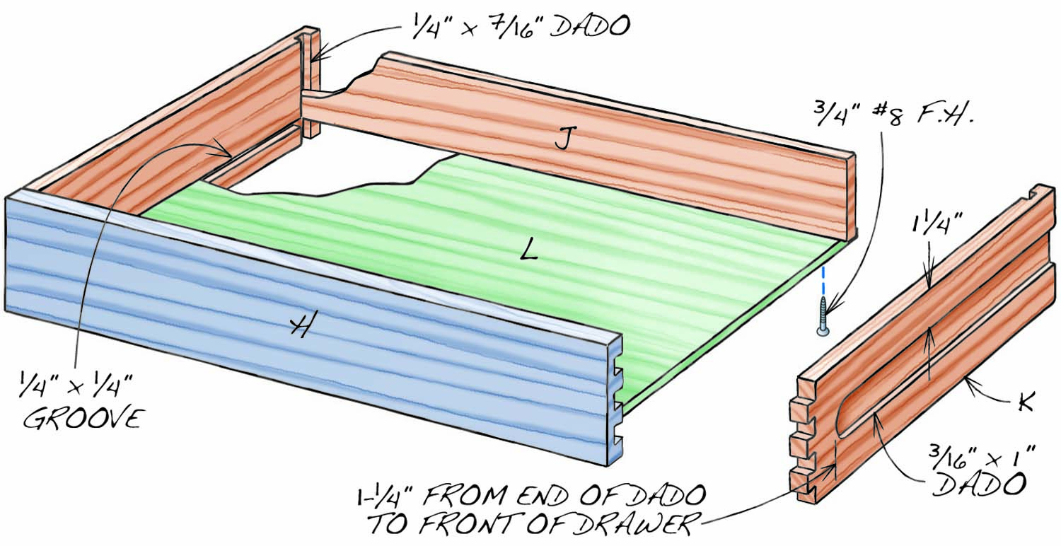
Fig. 02. Drawer (3-D exploded view)
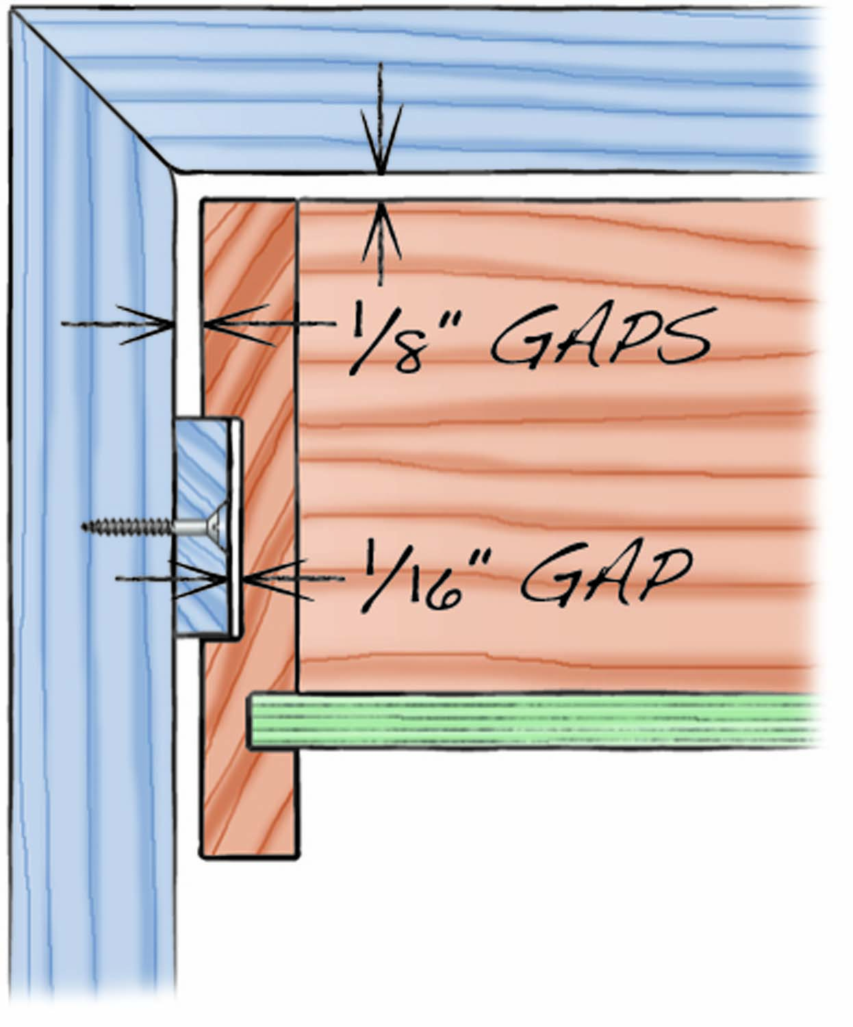
Fig. 03. Drawer and Case Cross Section (2-D, like Fig. 03-1 scrap)
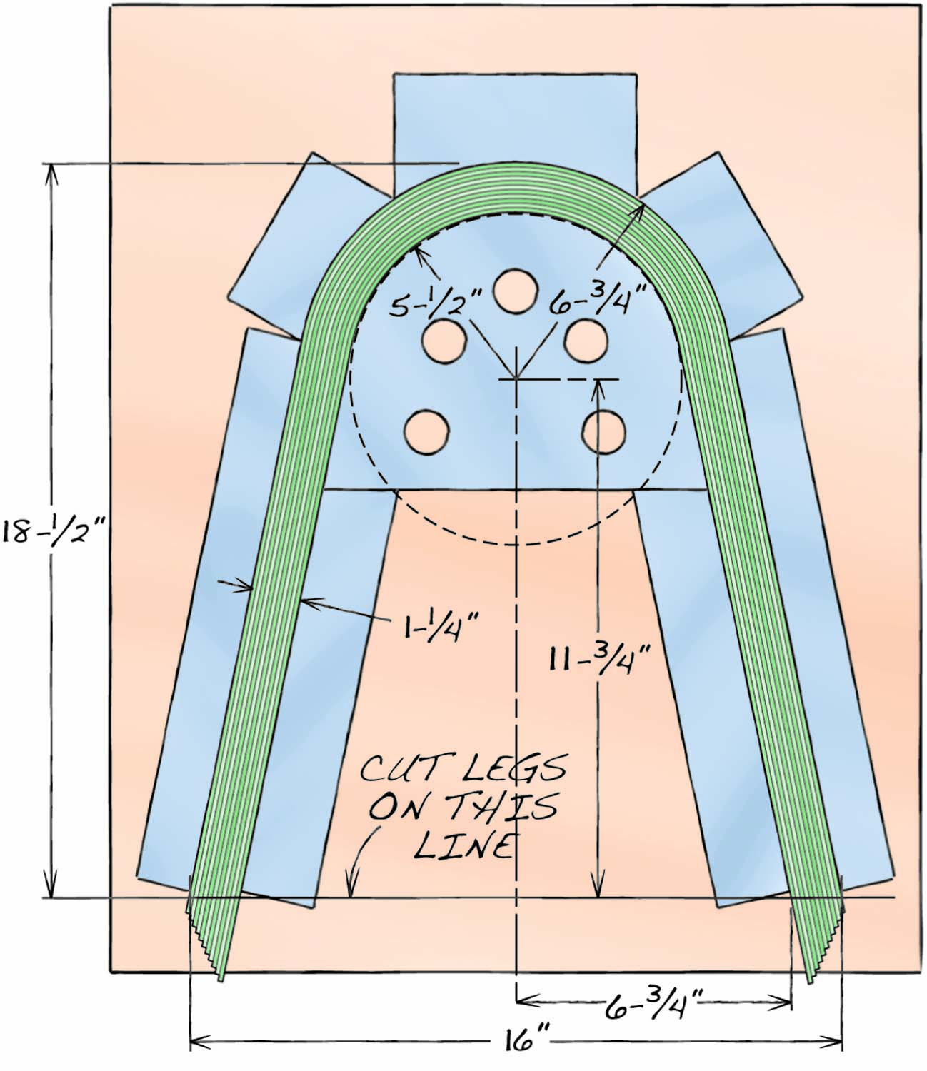
Fig. 04. Bending Form (2-D, include leg and blocks, but not clamps)
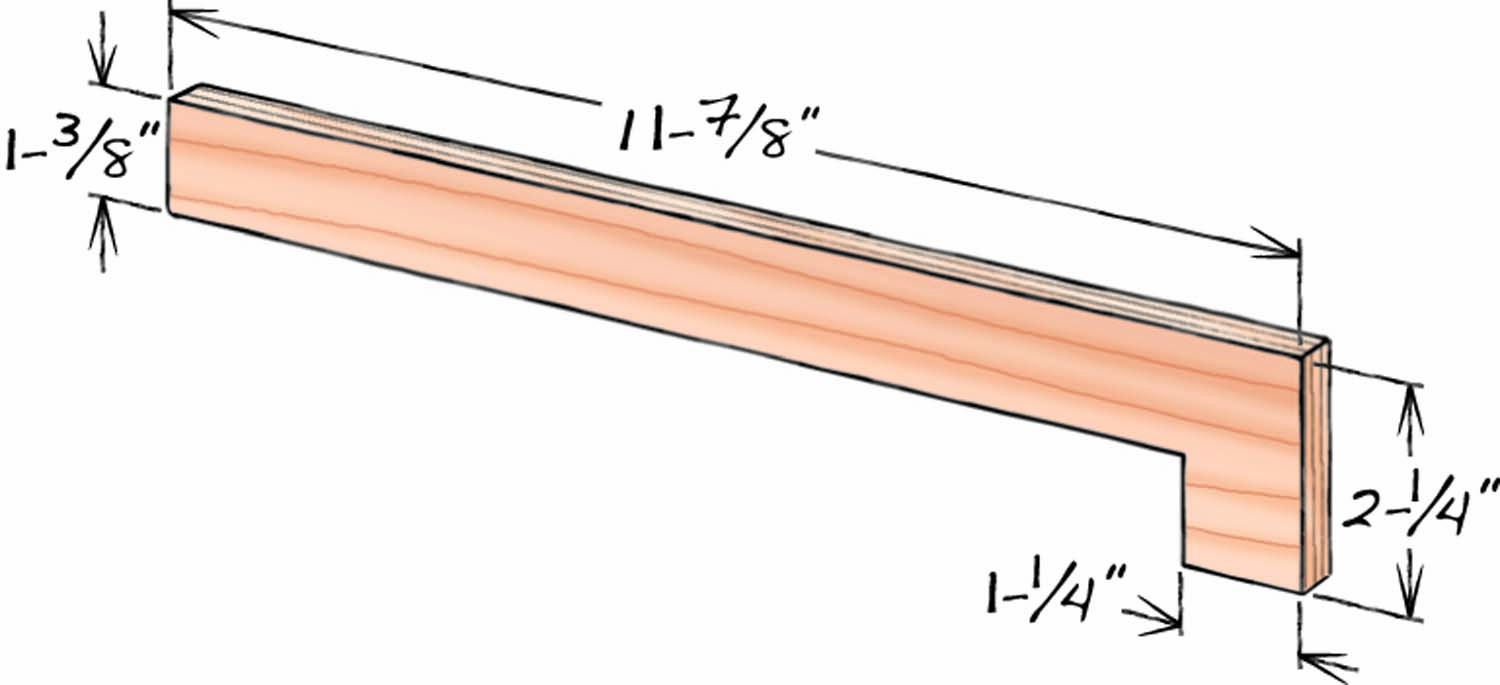
Fig. 05. Drawer Guide Gauge
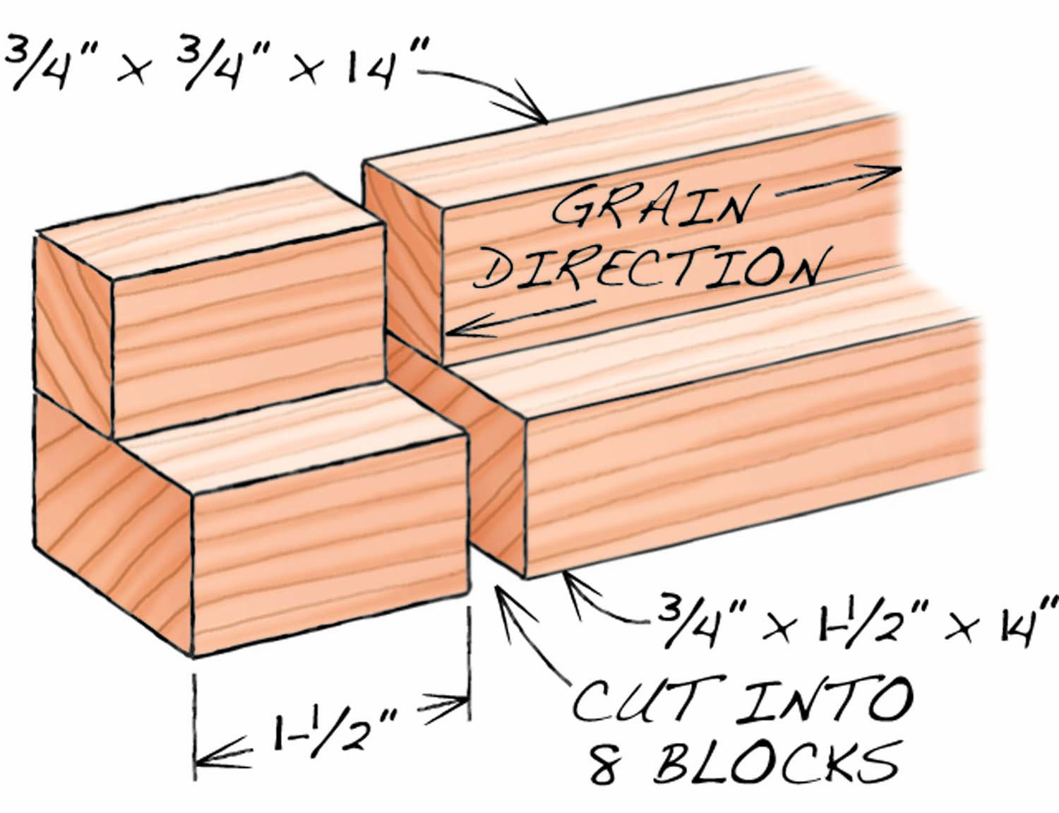
Fig. 06. Clamping Block (3-D, just the block, no string)
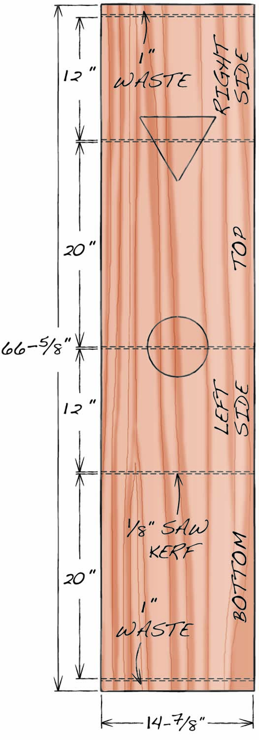
Fig. 07. Plywood Cutting Diagram
Cutting List
|
Metro Table |
||||
|
Overall dimensions: 21-1/2″ H x 22-1/2″ W x 16″ D |
||||
|
Part |
Name |
Qty. |
Material |
Th x W x L |
|
A |
Side |
2 |
Oak plywood |
3/4″ x 14-7/8″ x 12″ |
|
B |
Top and bottom |
2 |
Oak plywood |
3/4″ x 14-7/8″ x 20″ |
|
C |
Back |
1 |
Oak plywood |
1/4 x 19-1/4″ x 11-1/4″ |
|
D |
Long edging |
2 |
Solid oak |
1/8″ x 13/16″ x 21″ (a) |
|
E |
Short edging |
2 |
Solid oak |
1/8″ x 13/16″ x 13″ (a) |
|
F |
Leg |
2 |
Laminated oak |
1-1/4″ x 1-1/4″ x 18-1/2″ (b) |
|
G |
Drawer guide |
2 |
Yellow poplar |
1/4″ x 15/16″ x 14″ |
|
H |
Drawer front |
1 |
Solid oak |
3/4″ x 3″ x 18-1/4″ (c) |
|
J |
Drawer back |
1 |
Yellow poplar |
7/16″ x 2-1/4″ x 17-7/8″ |
|
K |
Drawer side |
2 |
Yellow poplar |
7/16″ x 3″ x 14-1/4″ |
|
L |
Drawer bottom |
1 |
Oak plywood |
1/4″ x 17-3/4″ x 14″ |
|
Notes: (a) Cut length to fit; trim to final width after gluing to case. (b) The legs are made from 22 layers of 1/16″ veneer, cut into 1-3/8″ wide x 50″ long strips. (c) The exact length is 1/4″ shorter than the cabinet’s opening. |
||||
Miter the Plywood
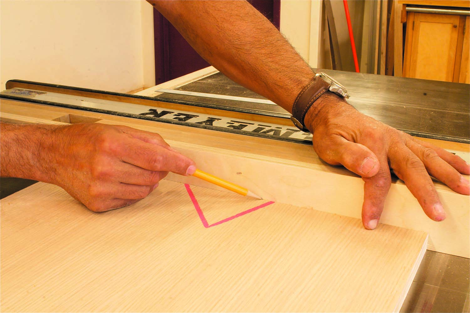
Photo 2. Set up the saw to cut miters on the ends of the pieces. First, mark the thickness of the plywood on a sacrificial fence.
Next, you’ll cut miters on the end of each piece—without shortening its length. Set up the saw by clamping on a sacrificial fence. Draw a line on the fence indicating the precise thickness of your plywood (Photo 2).
If you cut each miter in one shot, the offcut will be trapped between the blade and fence. It might shoot back at you. I use a backup board to prevent this, but you could also batch all of the boards and nibble away at the miters in stages, raising the blade about 1/8″ at a time. This method avoids creating offcuts; all the waste is reduced to dust.
Photo 3. Tilt the blade 45° and raise it to cut a hair below this line. Adjust the fence so the teeth cut all the way into it.
Setting up the final cut is fussy (Photo 3). You’ll only want to do this once, so each piece should be ready to go. Your goal is to cut a miter that leaves behind only a whisker of the board’s original end (Photo 4). You’ll probably need to make a number of test cuts to adjust the height of the blade and position of the fence. When you’re set, it’s a good idea to cut every end twice to make sure the mitered edges are straight.

Photo 4. Saw mitered edges on the plywood. When the blade and fence are set correctly, you should be left with a knife edge that leaves the piece at its original length.
Glue the Case
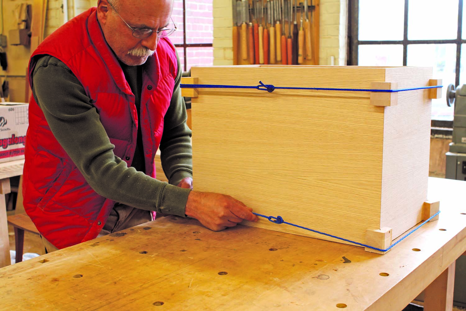
Photo 5. Glue the case together. You don’t need clamps; I use nylon tent cord, which has some stretch, to apply pressure to the joints.
I don’t use splines to reinforce the miters; the joints are strong enough without them. I don’t use clamps for the glue-up, either. Instead, I pull the assembly tight with stretchable nylon tent cord (Photo 5). Blocks placed at all four corners help square the box and keep the cord from digging into the miters. Glue up and cut a set of these blocks before assembling the case (Fig. 06).
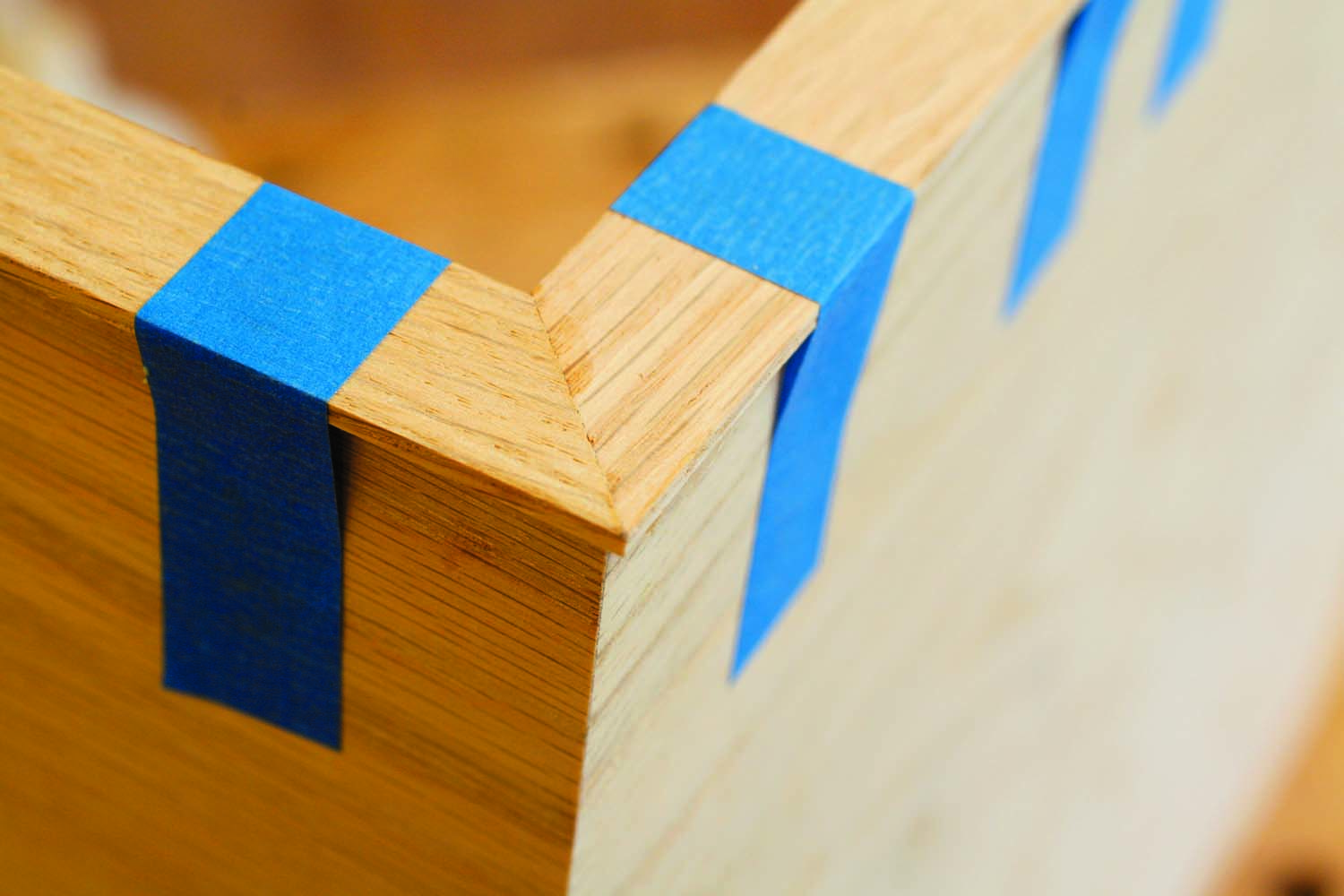
You’ll probably want a helper to hold the case together while you position the blocks, pass the cord around them and knot it tight. If you’re working alone, tape the joints together before you apply the glue. To do this, place all the parts face up on a long bench and butt them end-to-end. Stretch a half-dozen pieces of tape across each joint and flip the entire assembly over. Apply the glue, then fold the pieces together and apply more tape across the last joint.
After tightening the cords, check the case to be sure it’s square. You may have to nudge it one way or another to get it right. If any of the miters have small gaps, try closing them up by gently rubbing them with a burnisher or the round shaft of a screwdriver. Wait overnight, to let the glue dry hard, before continuing to work on the case.
Apply the Edging
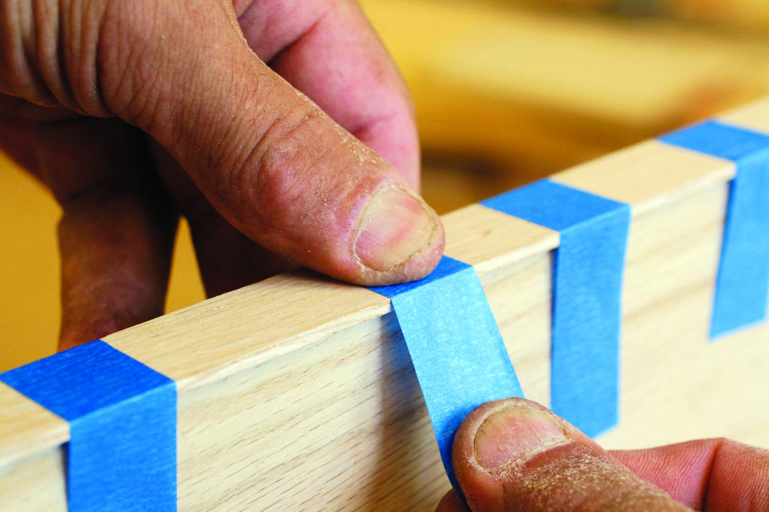
Photo 6. Glue 1/8″ thick edging around the front of the case. Clamps aren’t necessary here, either; tape provides adequate pressure.
Saw 1/8″ strips (D and E) to use as edging. Note that the edging isn’t mitered at all four corners; the bottom corners are butt joints. Start with the long piece for the top. Miter both ends, apply glue and tape the piece to the plywood (Photo 6). Make sure the edging overhangs both sides. Miter the short pieces for the case’s sides and glue them; finish up with the butted piece, along the case’s bottom.
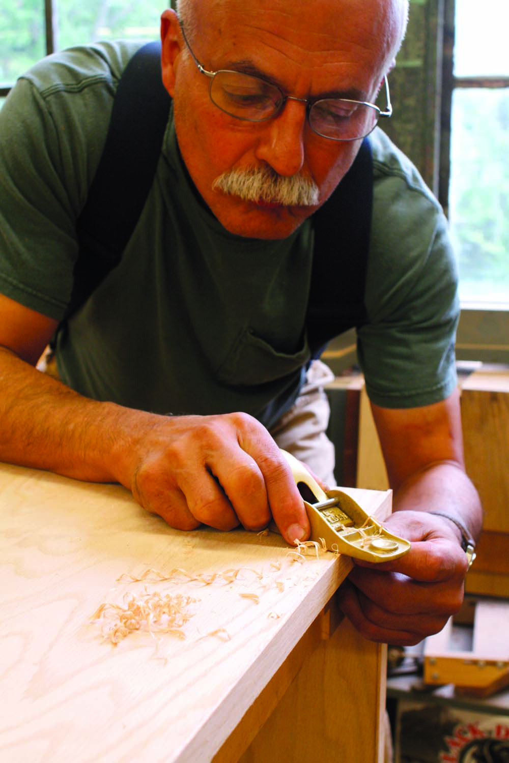
Photo 7. Plane the edging until it’s nearly flush with the plywood, then finish up with a scraper, file or sandpaper.
Remove the tape after 30 minutes or so, before the glue fully cures. Scrape off any squeeze out with a putty knife. The next day, level the edging close to the plywood with a plane (Photo 7). Level it flush with a scraper or sandpaper. (You could also use a flush-trim router bit for the whole process.) Use a file to level the inside corners; neither a plane nor a router will work here.
Laminate the Legs
The legs are composed of 22 layers of 1/16″ thick wood glued together. Rather than resaw all these pieces, cut the strips from extra-thick quartersawn red oak veneer. To rip the veneer, make a bundle of ten or so pieces and cut them into 1-3/8″ wide strips on the bandsaw.
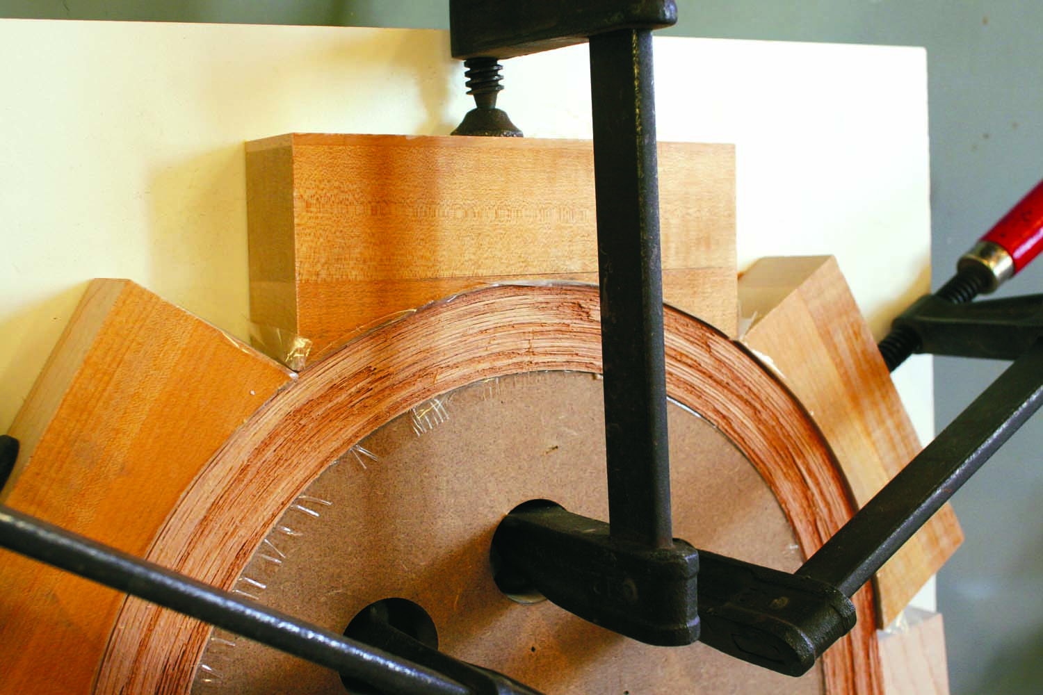
You’ll bend and clamp these strips around a form (Fig. 04). Build the form from two layers of 3/4″ MDF or plywood and screw the pieces to 3/4″ melamine or plywood. Run packing tape around the form to keep glue from sticking to it. You’ll also need to make three curved blocks to squeeze the laminations to the form. The radius of these blocks should exactly match the outside radius of the leg, as shown in the diagram. Put packing tape on these blocks, too.
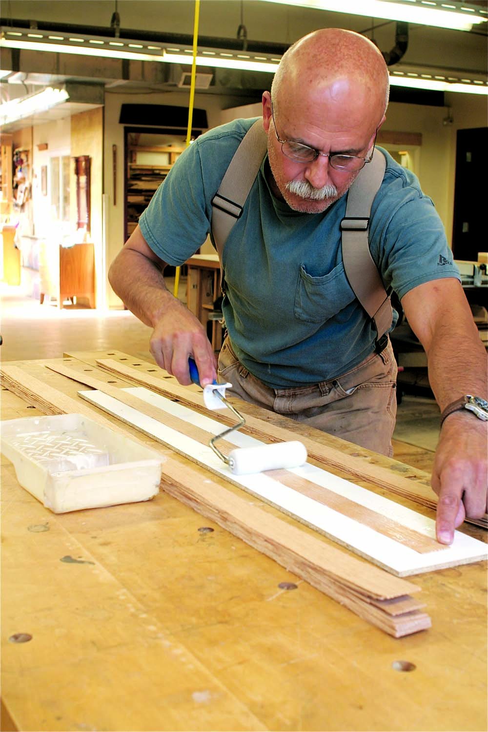
Photo 8. Make the legs by gluing and stacking strips of 1/16″ thick veneer. You have to work pretty fast, so apply the glue with a roller.
It’s a good idea to have help during the glue-up. One person bends the laminations around the form, while the other puts the blocks in place and tightens the clamps.
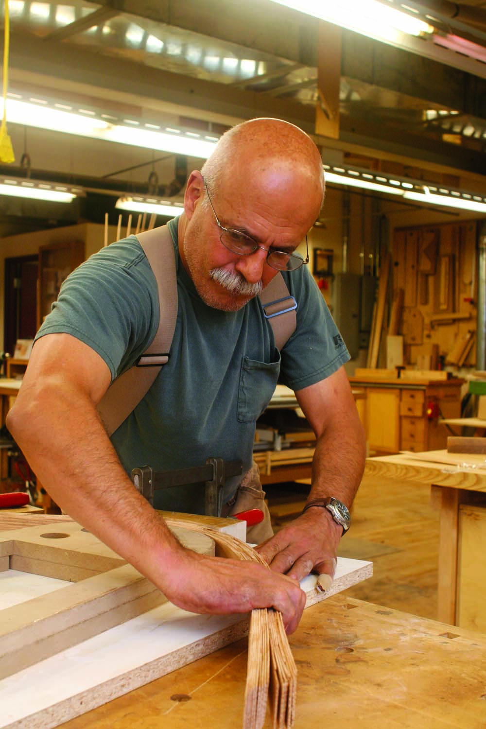
Photo 9. Bend the stack of laminations around a form.
The whole process starts by rolling a thin layer of yellow glue on one side of all the strips and piling them in a stack (Photo 8). Place the stack on the form, centered on the arch (Photo 9). Clamp the middle curved block first, then work your way down both sides (Photo 10). Before clamping each section, you’ll probably have to smack the laminations with a mallet a few times to force them flush. Leave the laminations clamped in the form overnight.
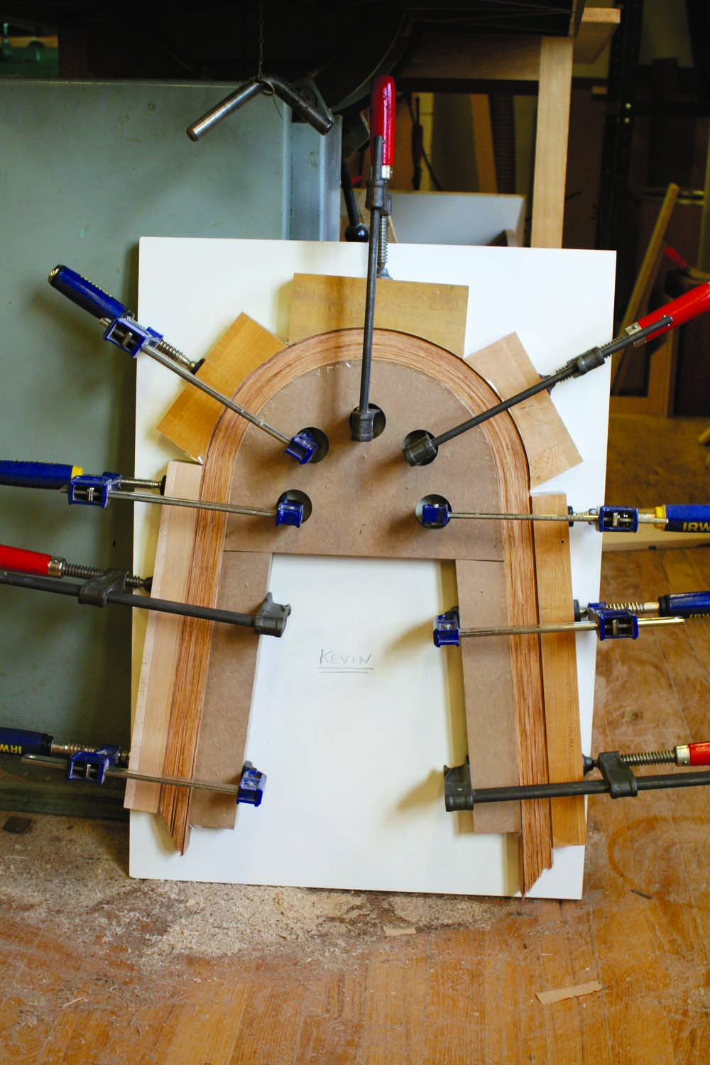
Photo 10. Clamp blocks around the form to squeeze the laminations together. This process creates a very stiff pair of legs.
Mount the Legs
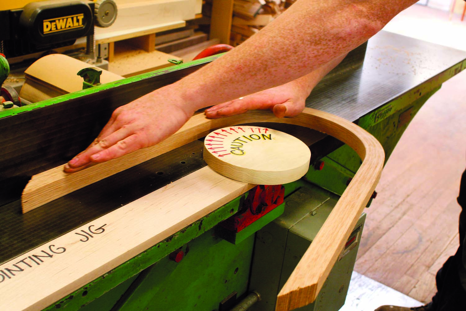
Photo 11. Flatten one side of the legs on the jointer. Safety caution: You must use a shop-made guard and a support board.
Your next task is to flatten one side of the legs. I’ll show you how I use a jointer to do this (Photo 11), but I’d like to caution you that this method requires a steady hand and a special jig. You must always keep your fingers on top of the wood, never on the sides. Alternatively, you could use a plane or perhaps a belt sander to level both sides of the legs.
The jig consists of a support board and a round guard. The support board is clamped to the jointer’s rabbeting ledge and widens the jointer’s bed. The guard is elevated 1/16″ above the support board—to clear the knives—and is fastened to it. Position the jointer’s fence about 2″ away from the guard. The guard’s round shape allows you to flatten the entire side of a leg in one pass by rotating the leg as you go.
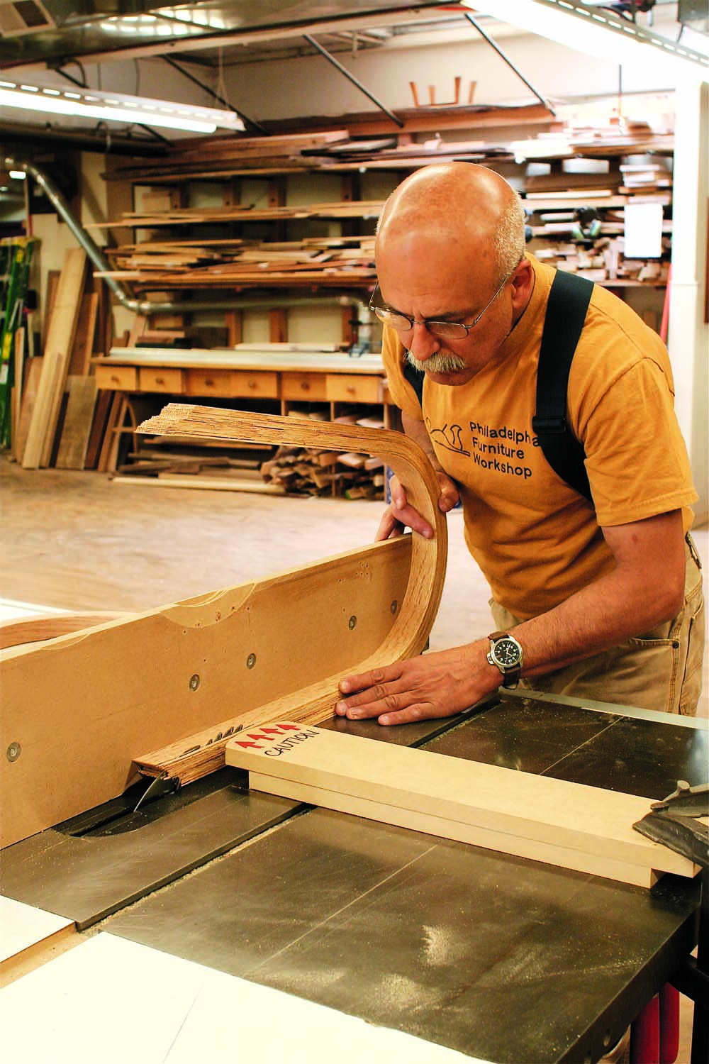
Photo 12. Rip the legs to width on the tablesaw. Newer saws are equipped with riving knives, which help prevent kickback. Safety caution: You must use a tall fence and clamp a guard board to the saw.
Rip the legs to final width on the tablesaw (Photo 12). This operation also takes a steady hand and an auxiliary guard. Position the end of the guard near the blade and clamp it to the top of your saw. Install a tall auxiliary fence to steady the leg as you cut. Raise the blade about 1-1/2″ high, but no more.
The most conservative way to rip the leg is to push it straight through the saw, as shown in the photo, then turn the leg over and repeat the operation. Plane the uncut portion, on the curve, by hand. If your saw is equipped with a riving knife immediately behind the blade (which helps prevent kickback), and you’re very careful, you can saw the entire leg in one pass. (Don’t attempt this if your saw doesn’t have a riving knife.) Slowly rotate the leg when you get to the curved portion and guide the final, straight portion of the leg with a push stick.
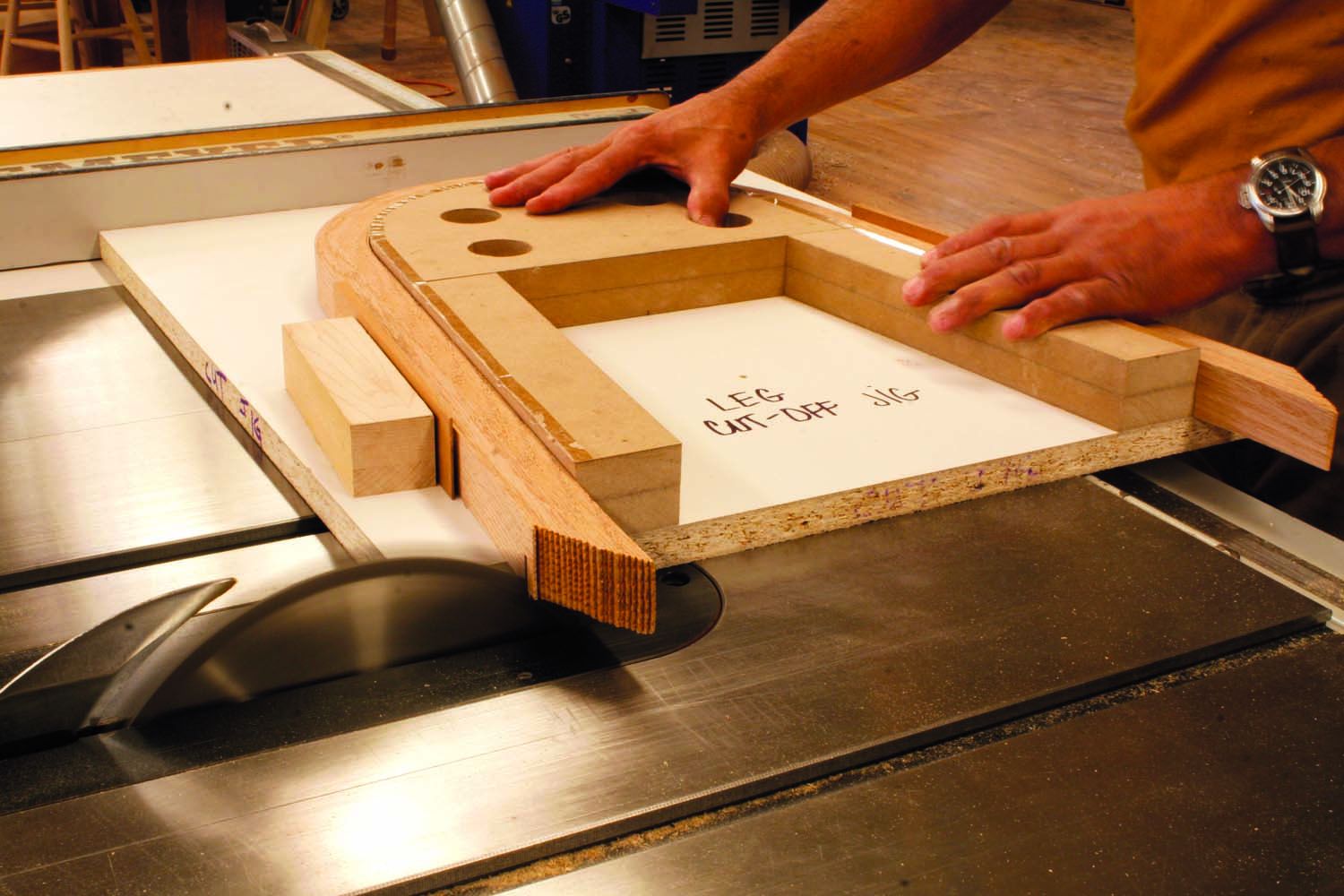
Photo 13. Cut the legs to length. Place the legs back on the gluing form to hold them in the correct position.
Use the bending form as a jig to cut the legs to length (Photo 13). To align the legs on the case, cut a board 9″ wide and clamp it even to the ends of one of the legs (Photo 14). Center the leg on the case, then trace around it with a pencil. You’ll be fastening the leg to the case with screws, from the inside (Fig. 01). Remove the leg and mark where the screws will go on the outside of the case. Drill 1/8″ pilot holes through the case, from the outside. On the inside of the case, counterbore these holes to receive wood plugs. Enlarge the holes so your screws slip through.
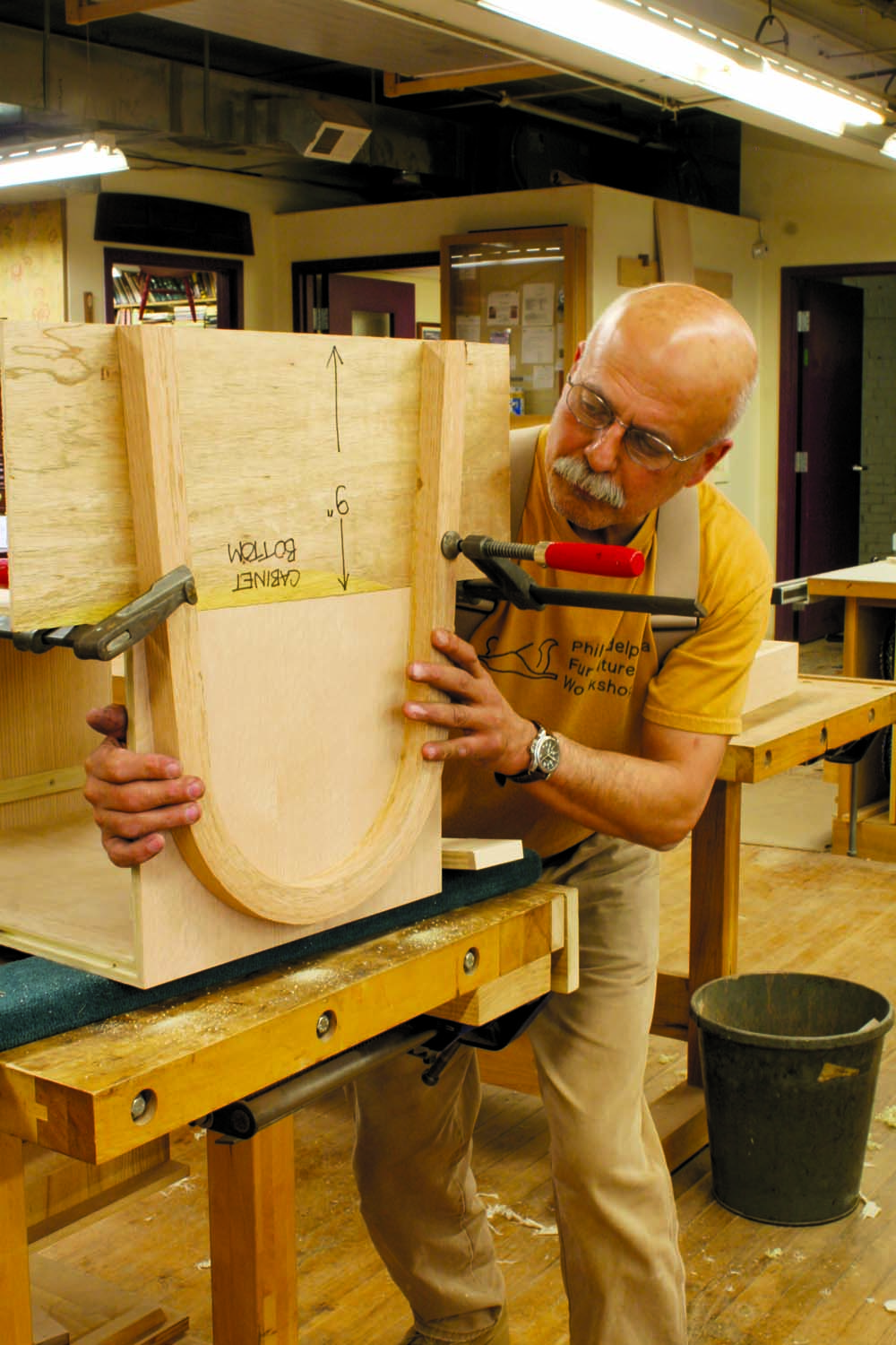
Photo 14. Mount the legs to the case. Clamp a guide board to the legs to make sure they’re even. Fasten the legs with screws.
Sand the entire case and both sets of legs. Clamp the legs back to the 9″ board and fasten them to the case. Glue plugs on top of the screws and level them.
Add a Drawer
The drawer runs on guides (G) that are screwed to the side of the case (Fig. 03). On the drawing, note that there’s a 1/8″ gap between the drawer and the case, all around.
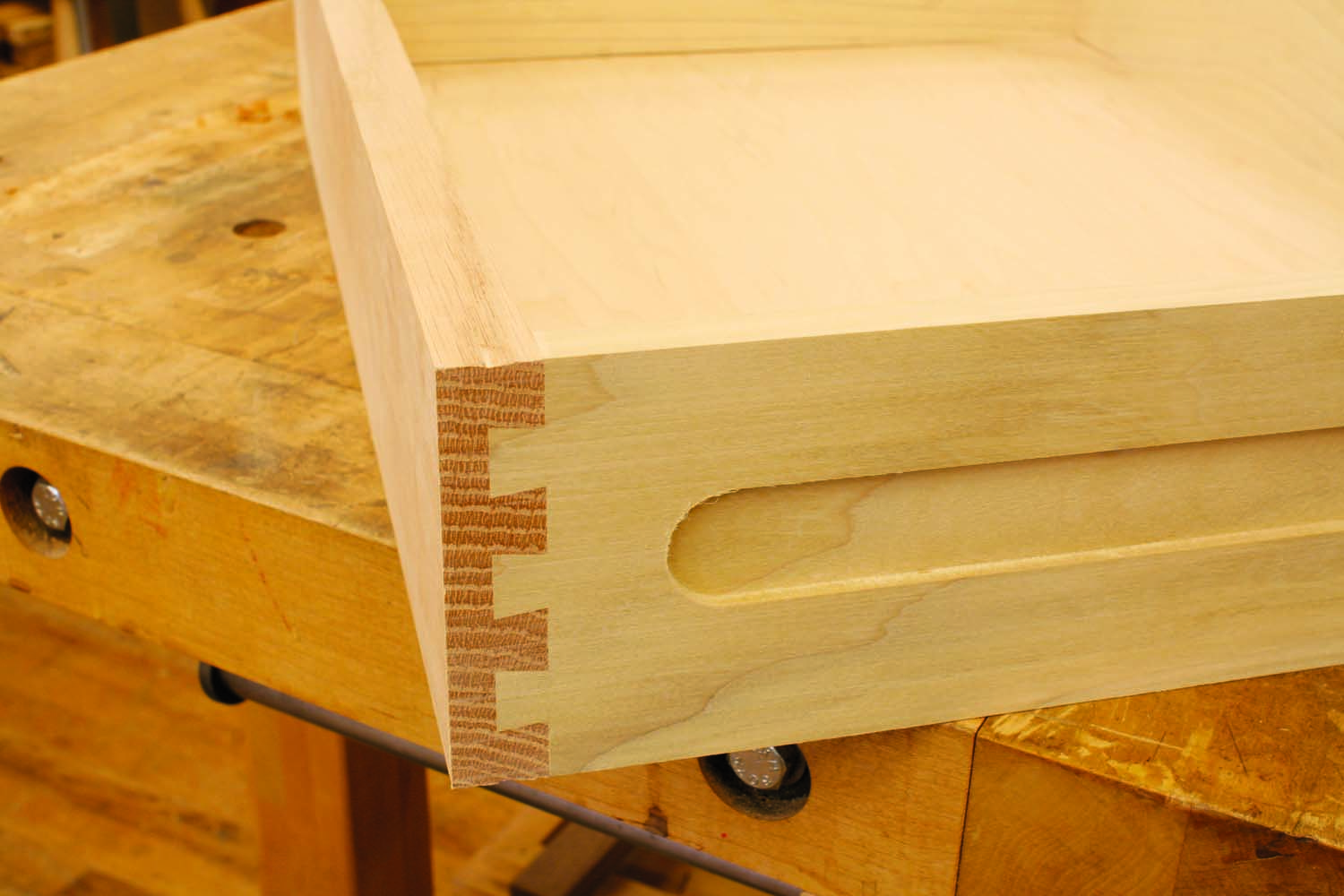
Mill the wood for the drawer front (H), back (J) and sides (K). Rip the front and back to final width. Trim the front exactly 1/4″ less than the distance between the two sides of your case. Cut the sides to width and length, then rout half-blind dovetails to join the sides to the front (Fig. 02). (I used a Porter-Cable 4210 jig, which spaces the dovetails 1″ apart.) Rout grooves for the drawer bottom (L) in all three pieces. Cut dadoes across the rear ends of the sides to receive the back, then temporarily assemble the front and sides. Trim the back piece to the correct length and cut the bottom to size. Glue the drawer together. Rout stopped grooves in both sides of the drawer.
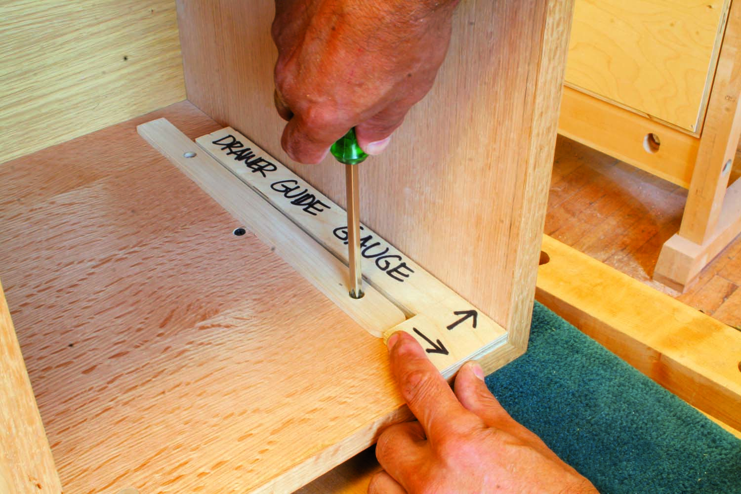
Photo 15. Fasten the drawer supports inside the case. Use a gauge block to position the supports.
Make the drawer guides. Drill and countersink two holes in each guide for mounting them to the case. You’ll need a gauge (Fig. 05) for locating the guides. Fasten the guides to the case (Photo 15) and slide in the drawer (Photo 16). If the drawer fits too tight between the drawer supports, remove one support and plane it thinner. If the drawer is too loose, remove one support and substitute a thicker one. Add the back to the case and you’re ready for finishing.
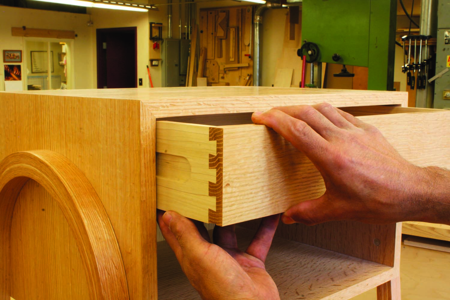
Photo 16. Slide in the drawer. The sides of the drawer ride against the drawer support, not the case. If the fit is too tight, side to side, remove one support and plane it thinner.
Here are some supplies and tools we find essential in our everyday work around the shop. We may receive a commission from sales referred by our links; however, we have carefully selected these products for their usefulness and quality.