We may receive a commission when you use our affiliate links. However, this does not impact our recommendations.
 So tell me—how many jigs do you have scattered around your shop? Is it true that a guy can’t have too many, just like you can’t have too many clamps?
Well, here’s one that I’ll bet you haven’t seen before. I designed it to make a corrugated lamp reflector, but when I was done, I realized that building the jig was almost as much fun as making the lamp. I’m hanging on to the jig because I’m sure it could be used for many more things. But don’t ask me just what—I’m still making plans!
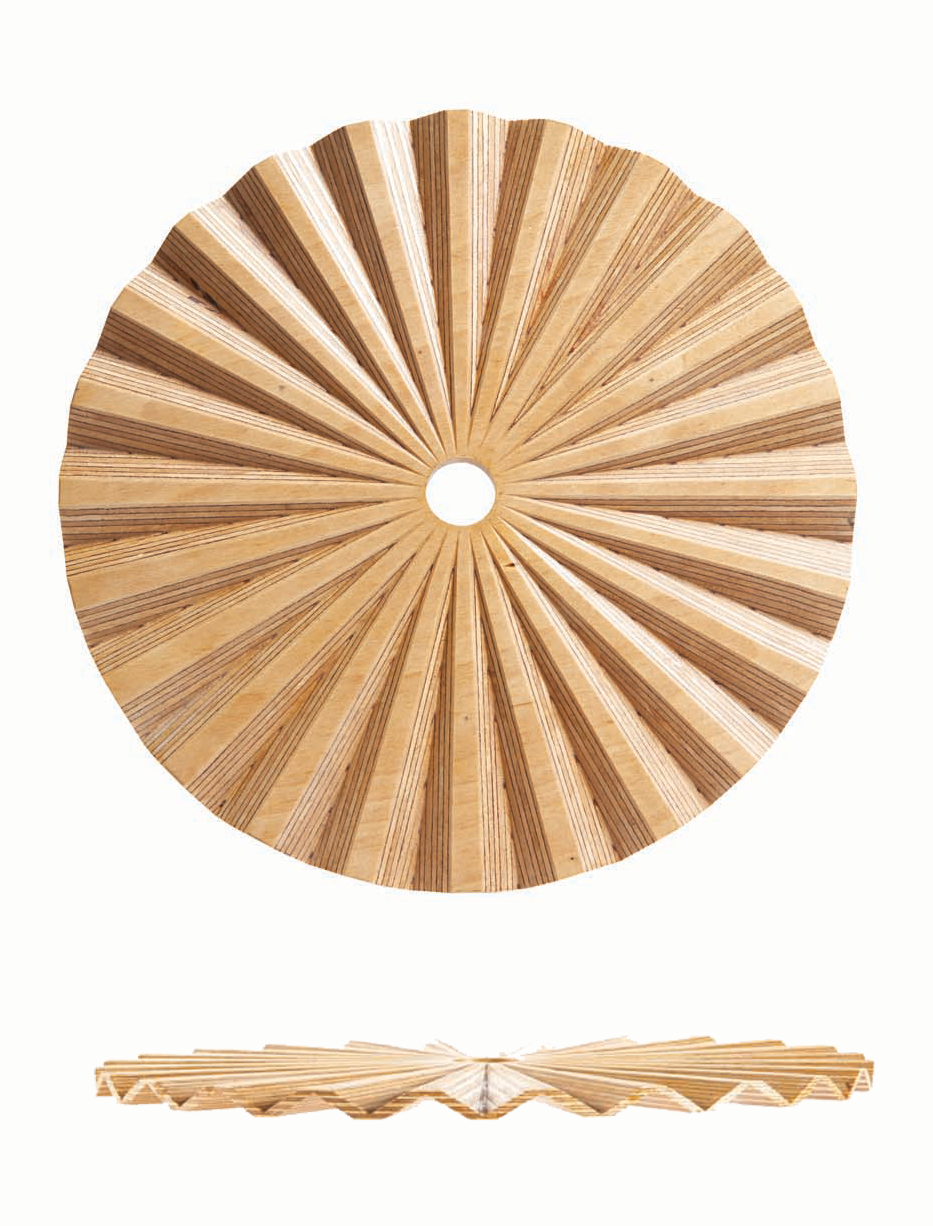
After designing this jig, I wondered, “What can I do with it?” Here’s my first project: a reflector shade for a lamp
Basically, the jig allows you to rout across a circle, making a pattern like the spokes on a wheel. You rotate the circle after each pass, using a dirt-simple system of indexing marks. I also designed the jig to tilt, so that the router could cut deeper on the circle’s perimeter than near its center. This has the effect of making the cuts taper in width and depth.
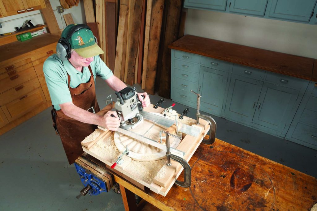
As I take you through the steps of building the jig, I’ll use the method required to rout one side of the lamp reflector to illustrate how to set it up. I hope this gets your imagination going!
Base and carriage
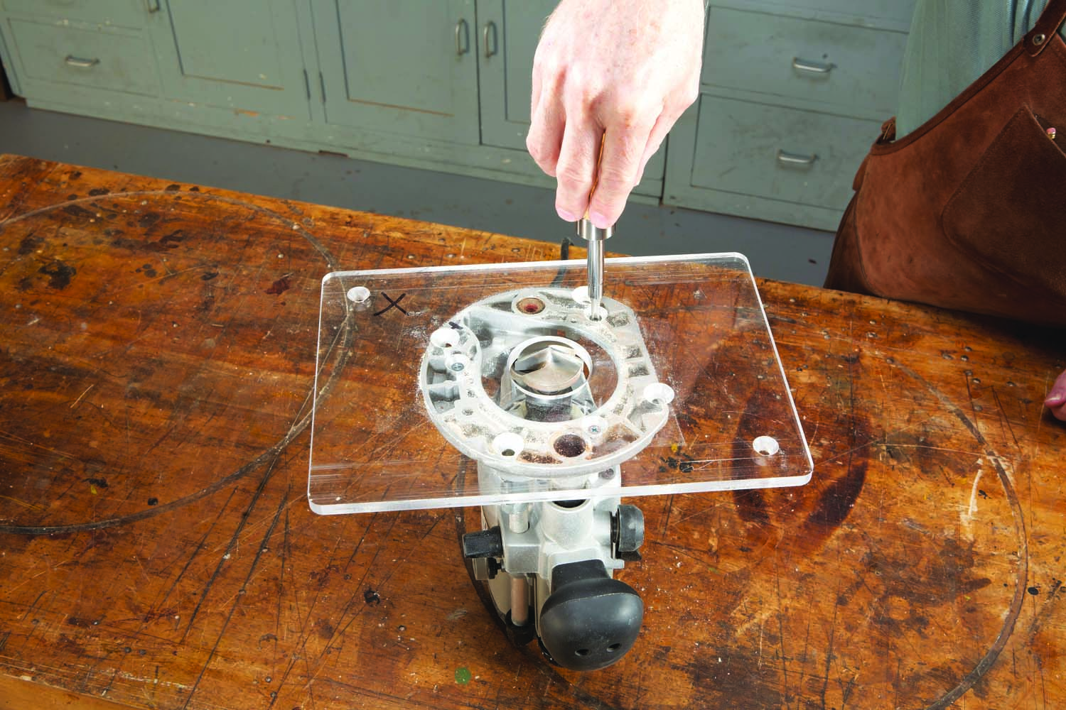
1. Fasten a large, rectangular plate to your plunge router. The plate must have a hole large enough to accommodate the bit you’ll be using—in this case, a very large V-groove cutter.
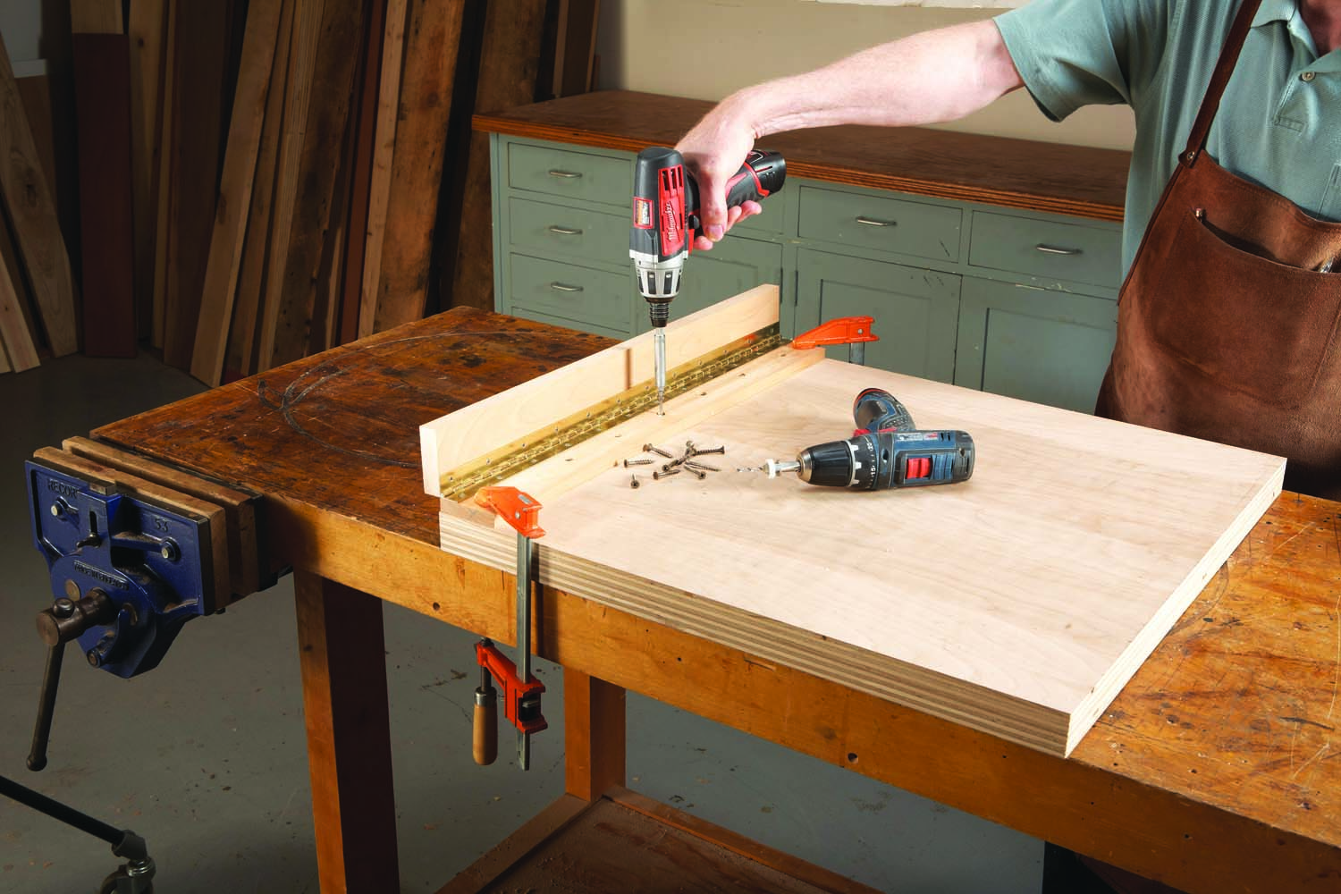
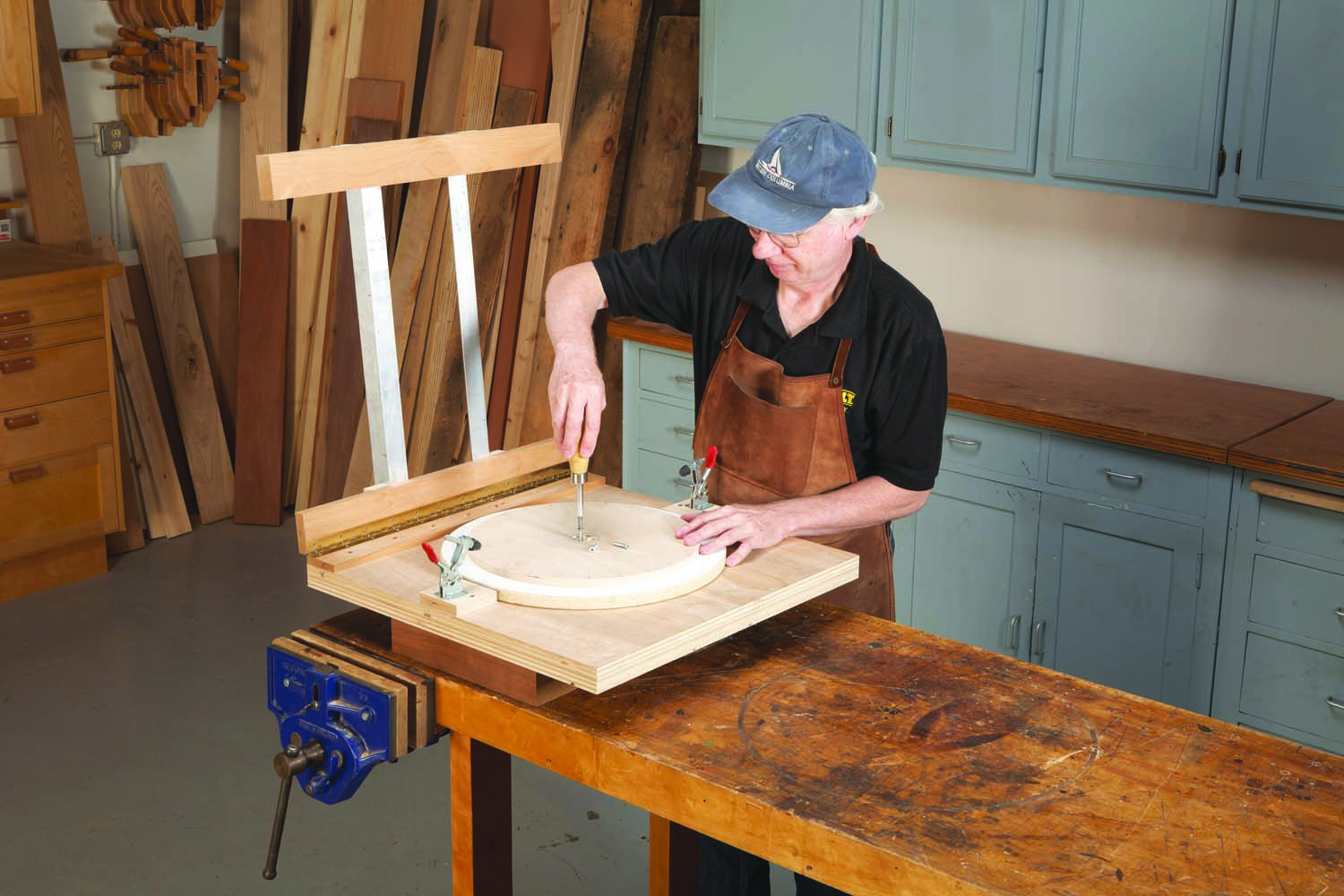
The first step in building the jig is to buy or make a large rectangular plate (A) for your plunge router (Photo 1). I used a 3/8″ clear acrylic insert designed for a router table. A plate that you can see through is handy for setting up the router’s depth of cut and checking on your progress as you rout, but it’s not strictly necessary. I’ll be using a very large V-groove bit (see Sources), so I had to drill a hole in the plate large enough to accommodate the bit. Remove the sub-base from your router to install the plate.
Next, build the jig’s base (B). Cut two pieces of plywood 24″ x 24″, glue them together, then trim the piece to final size. Mill some wood for the stretchers (C and D). Glue one of the 3/4″ pieces to a 1/2″ piece, then cut all of the pieces to final length. Use a hacksaw to cut a continuous hinge (E) the same length as the stretchers. Connect two of the stretchers with the hinge, then mount this assembly to the base (Photo 2).
2. Begin building the jig by fastening a pair of hinged stretchers to a double-thick plywood base.
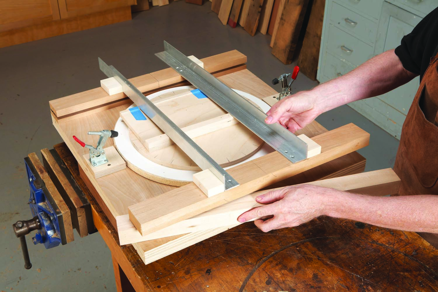
The next step is to make a carriage for the router. You want the router to ride in this carriage without wiggling, so it’s important to mount the carriage’s rails (F) the correct distance apart. Here’s one way to do it. First, cut the rails to length, then drill and countersink holes for their mounting screws (Fig C). (Be sure to countersink the holes deep enough so that the heads of the screws are below the surface of the rails.) Next, cut a 22″ long piece of plywood to stand in for the router plate. This piece must be exactly the same width as the plate. Finally, make some small blocks (G) to lock in the rail’s position.
3. Center a pair of aluminum angles on the stretchers, forming a carriage for the router plate. To space the angles, use a long board that’s the same width as the plate. Glue small blocks next to the angles.
To mount the carriage, draw a centerline on top of the hinged stretchers and on top of the rear stretchers. Draw a centerline around the 22″ piece of plywood as well. Place the plywood between the rails and align its centerline with the lines on the front and back stretchers (Photo 3). Double-check the carriage’s alignment with a framing square, then clamp the carriage so it can’t move. Glue the small blocks tight up against the rails. (Just rubbing them in place is adequate.) When the glue dries, clamp the blocks to the rails, then use a self-centering bit to drill pilot holes for the mounting screws (Photo 4). Install the screws, then remove all of the clamps and the plywood board. Place the router between the rails to make sure it glides smoothly on the carriage.
4. Clamp the angles to the blocks, then fasten the angles to the stretchers. Use a self-centering bit to drill the pilot holes.
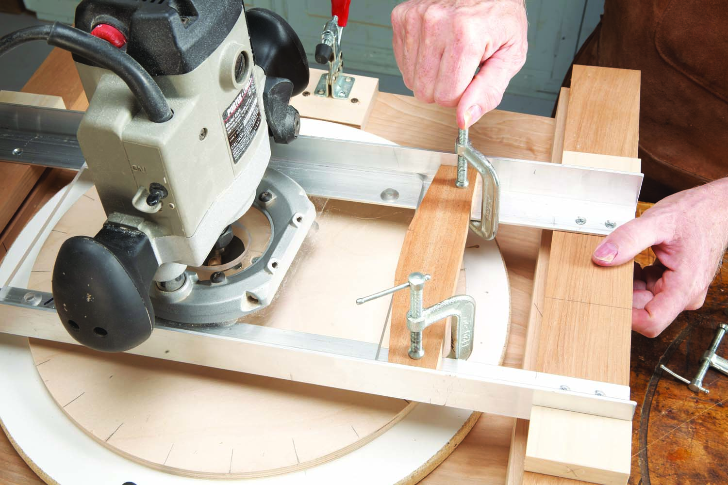
Next, mark the exact centerline of the bit (Photo 5). The best way to do this is to chuck a V-groove bit in the router, then rout a shallow groove into the top hinged stretcher. Mark the center of this groove with a pencil, then continue the line down the hinged pieces and across the base.
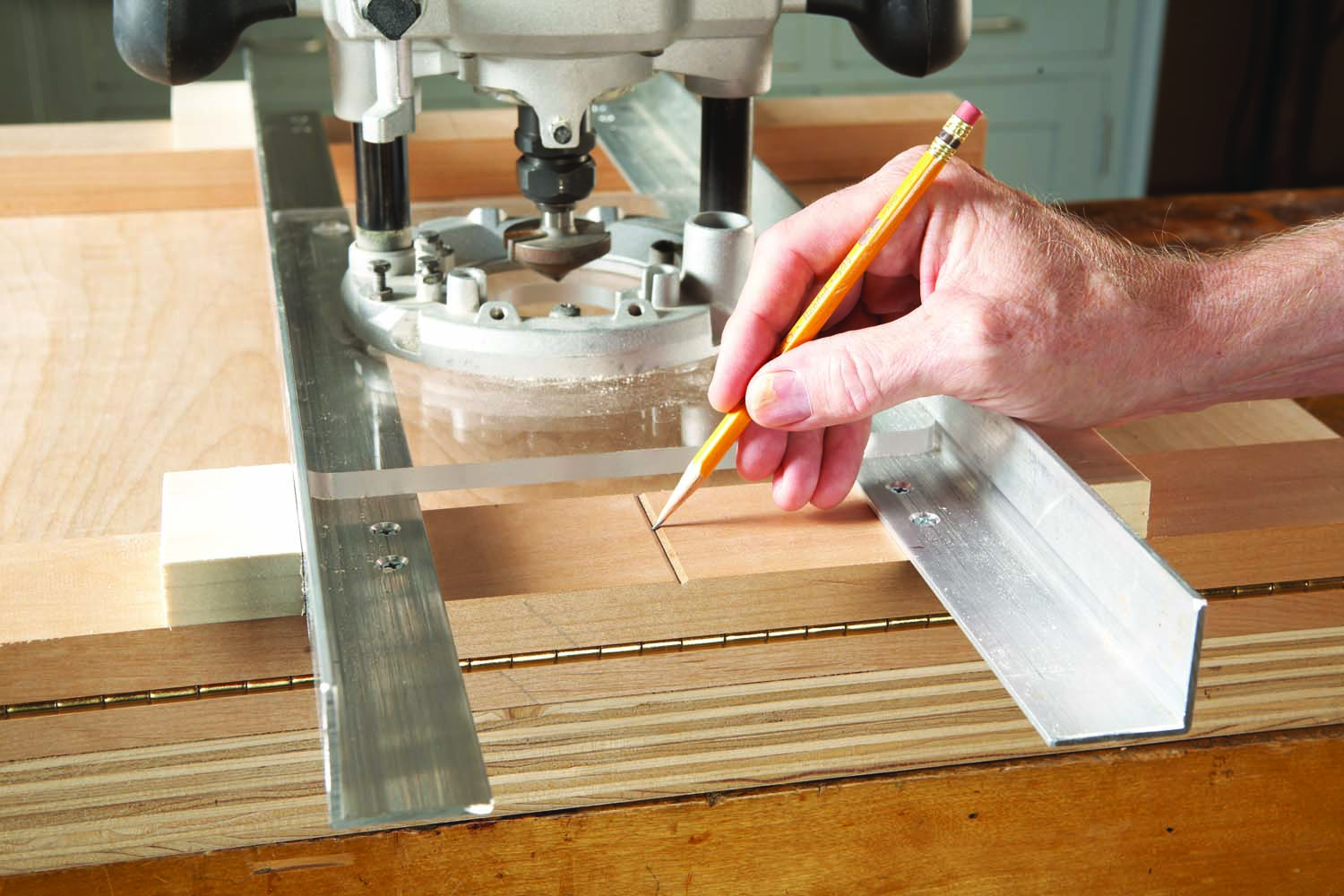
5. Slide the router between the angles and cut a shallow groove across the stretcher. Mark the precise center of the groove.

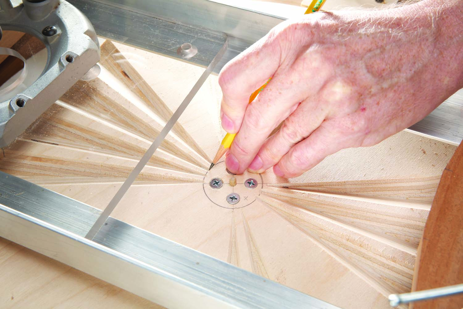
When you must drill a precisely perpendicular hole on an object that’s too large for your drill press, use a guide block (Photo 6). Drill the guide block on your drill press, then draw centerlines through the hole and around the block. To position the block, align these marks with centerlines on your project.
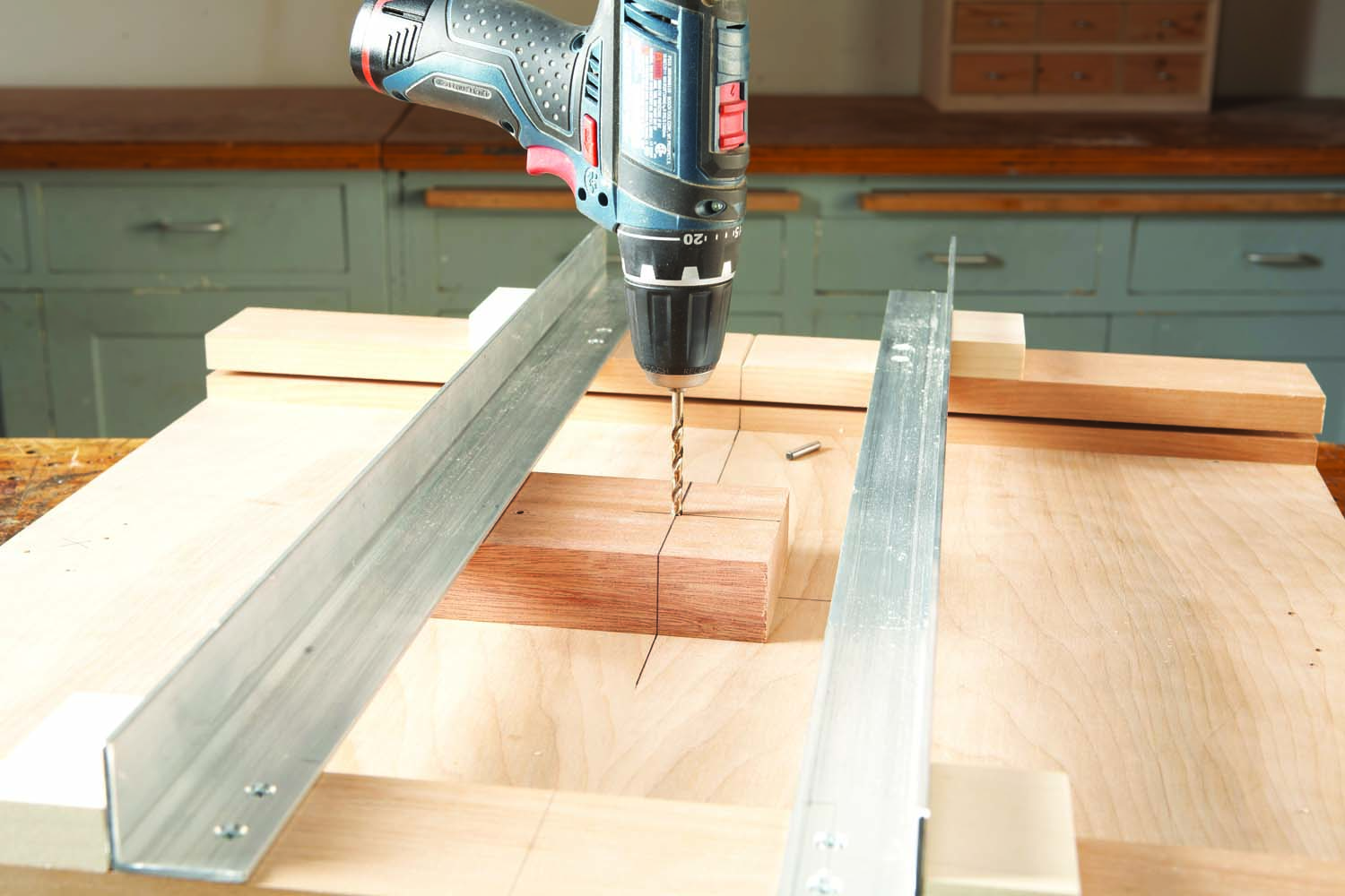
6. Extend the groove’s centerline across the jig’s base. Use a guide block to drill a 3/16″ hole in the base. Put a pin in this hole for rotating the jig’s turntable.
Place a short 3/16″ dowel in the base’s hole. (I use a metal dowel, but a wooden dowel will work just as well.) Make the turntable (H) and at least one practice workpiece using a circle-cutting jig (Photo 7). Be sure to use a 3/16″ pivot pin to match the hole in the rotary jig. After cutting out the turntable, I drilled four holes for 10-24 machine bolts near its center for fastening the workpiece (Fig. 01). I installed T-nuts in these holes, flush with the turntable’s bottom, to receive the bolts.
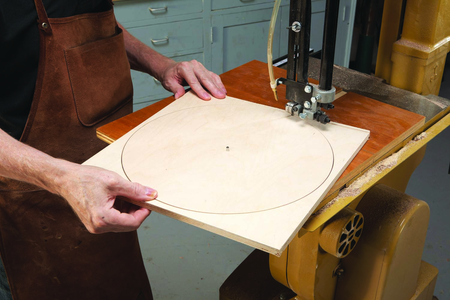
7. Saw a practice workpiece using a circle-cutting jig. Rotate the piece on a 3/16″ pin. Make the turntable in the same way.
Note: Use brass bolts, not steel ones as shown here. Brass will cause far less damage to a router bit if you accidentally hit the heads of the bolts.
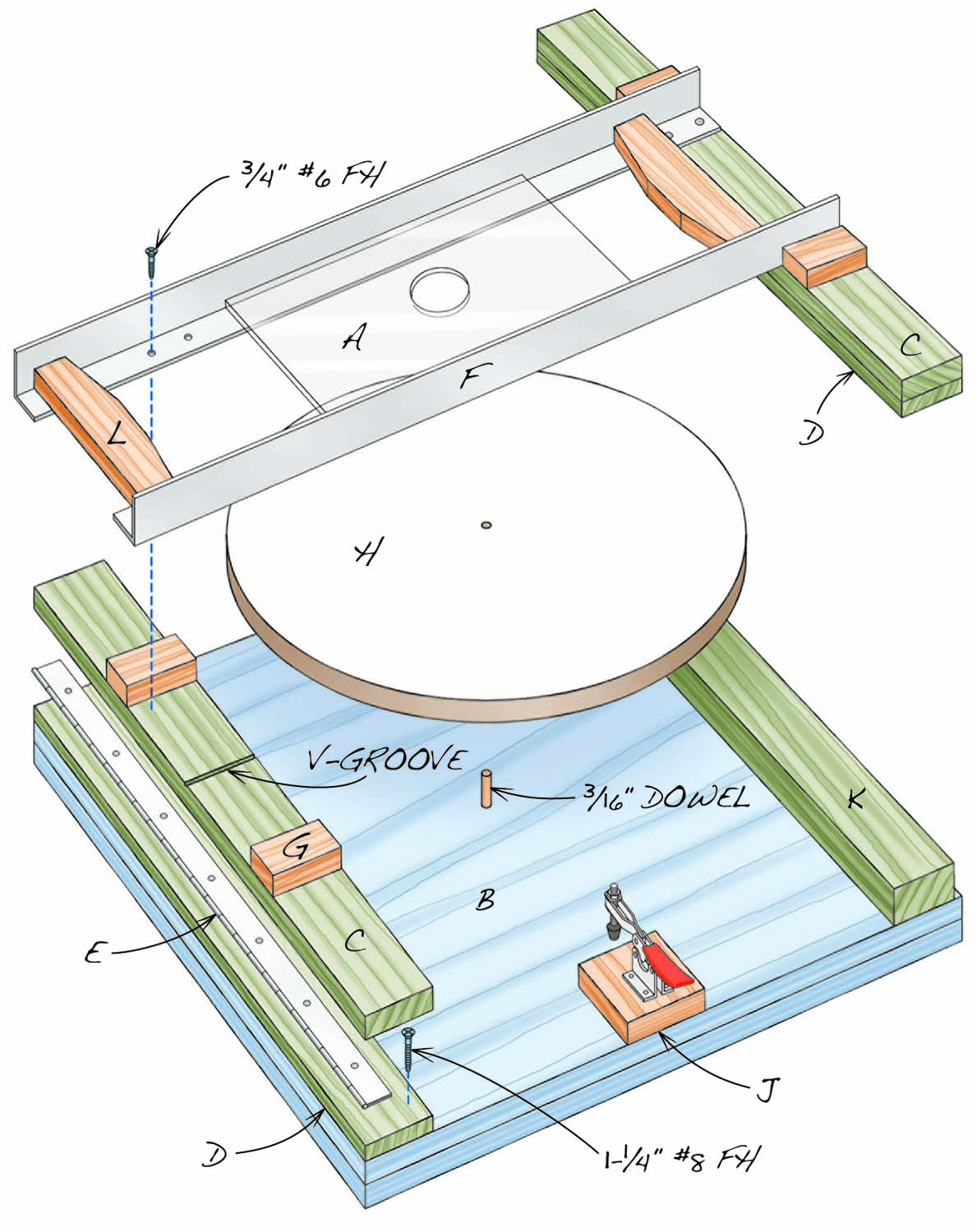
Fig. A. Exploded View
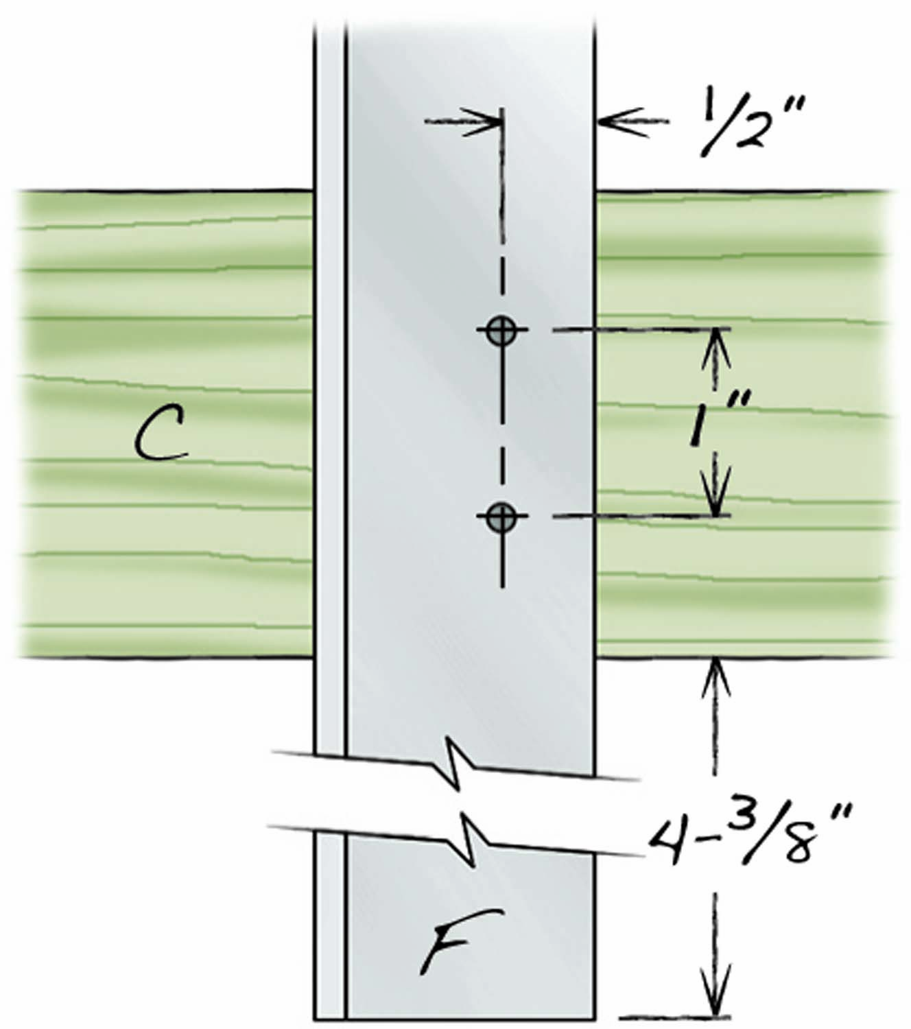
Fig. B. Detail of Rail Mouting Screws
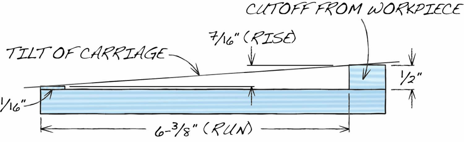
Fig. C. Angle – Setting Gauge
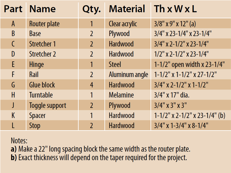
Cutting List
Indexing the workpiece
Of course, this approach won’t work with every project, since it requires drilling through the center of the workpiece. Alternatively, you could make the turntable the same size as the workpiece and clamp the workpiece directly to it using toggle clamps. But consider this: Clamping the turntable avoids putting pressure on a delicate workpiece. In any case, both methods require raising the toggle clamps on small blocks (J).
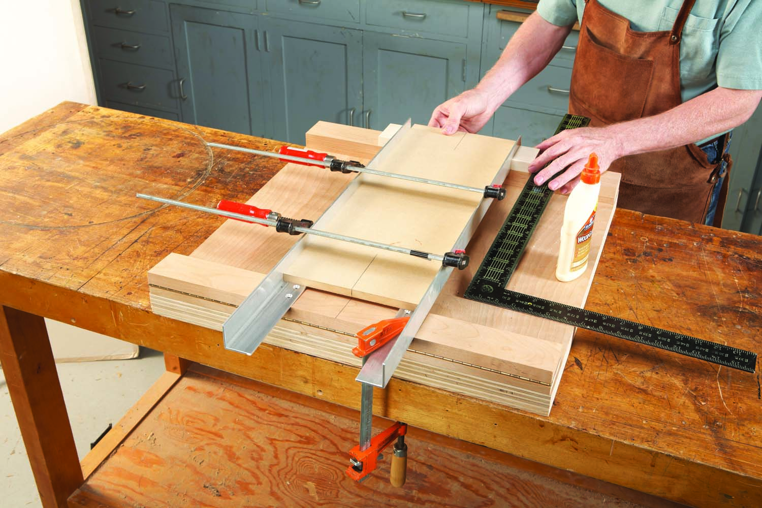
I don’t use a complicated indexing device to rotate the workpiece to an exact position. I just draw pencil lines. I use a computer to draw a pattern, then print it out full size. The reflector I’ll be making here is 14″ dia.—larger than a single sheet of printer paper. No problem: I just draw part of the pattern, print four copies, then stick a push pin through the “center” of all four pieces. To make a full pattern, I fan out the pieces and tape them together (Photo 8).
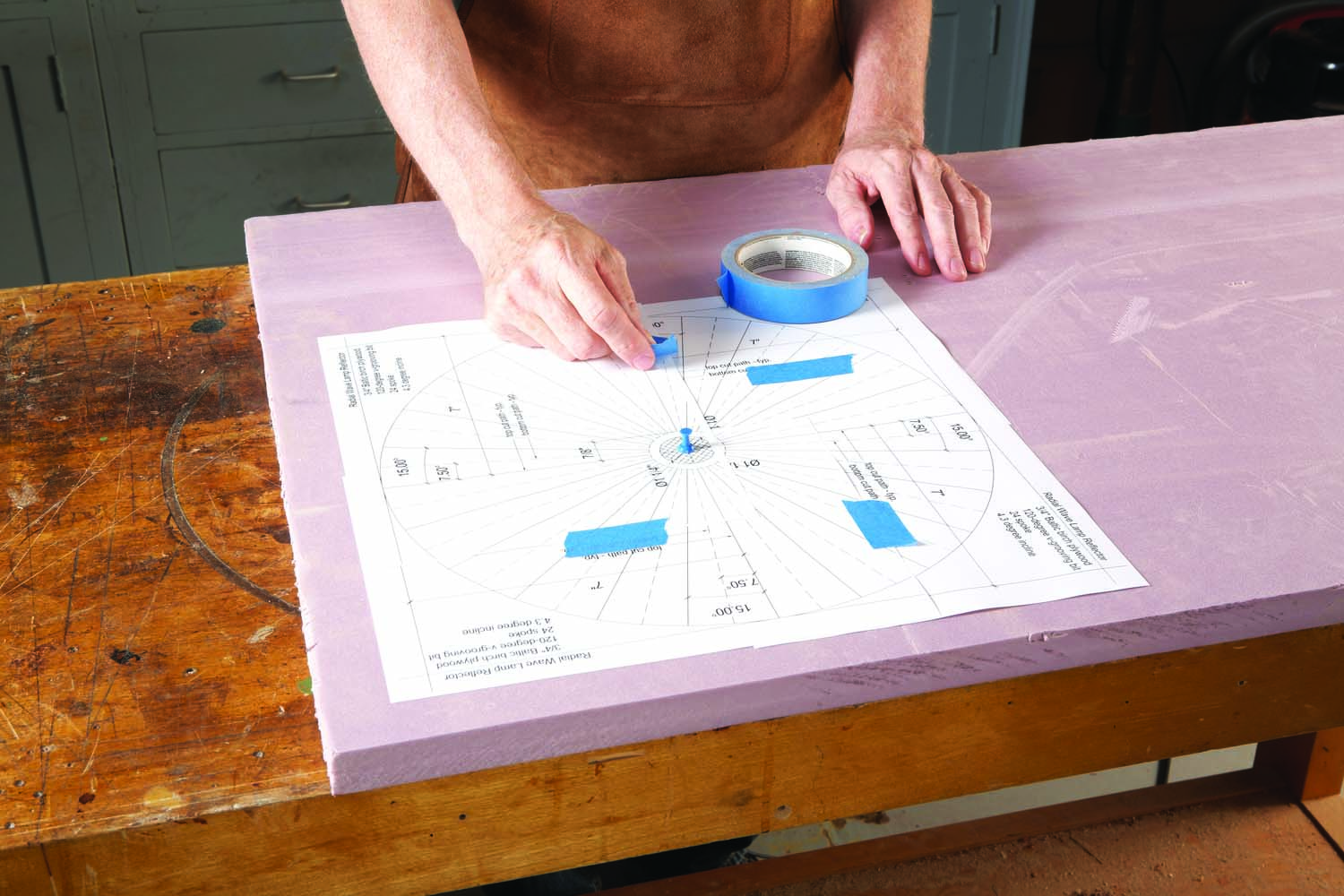
8. Make a pattern for the workpiece. This CAD drawing calls for 24 evenly-spaced V-grooves. It’s made from taping together four sheets of 8-1/2 x 11 paper.
The reflector requires 24 evenly-spaced grooves on both sides of the workpiece. I don’t need to draw the outline of each groove—just a short centerline. I use a scissors to cut each of the 24 pattern lines about an inch deep, then tape the pattern to the workpiece and trace each scissor cut (Photo 9). (To draw the opposite side, I turn the workpiece over and offset the pattern by half the distance between two tick marks.) Later on, I’ll show you an easy way to position the turntable to hit each line right on the money.
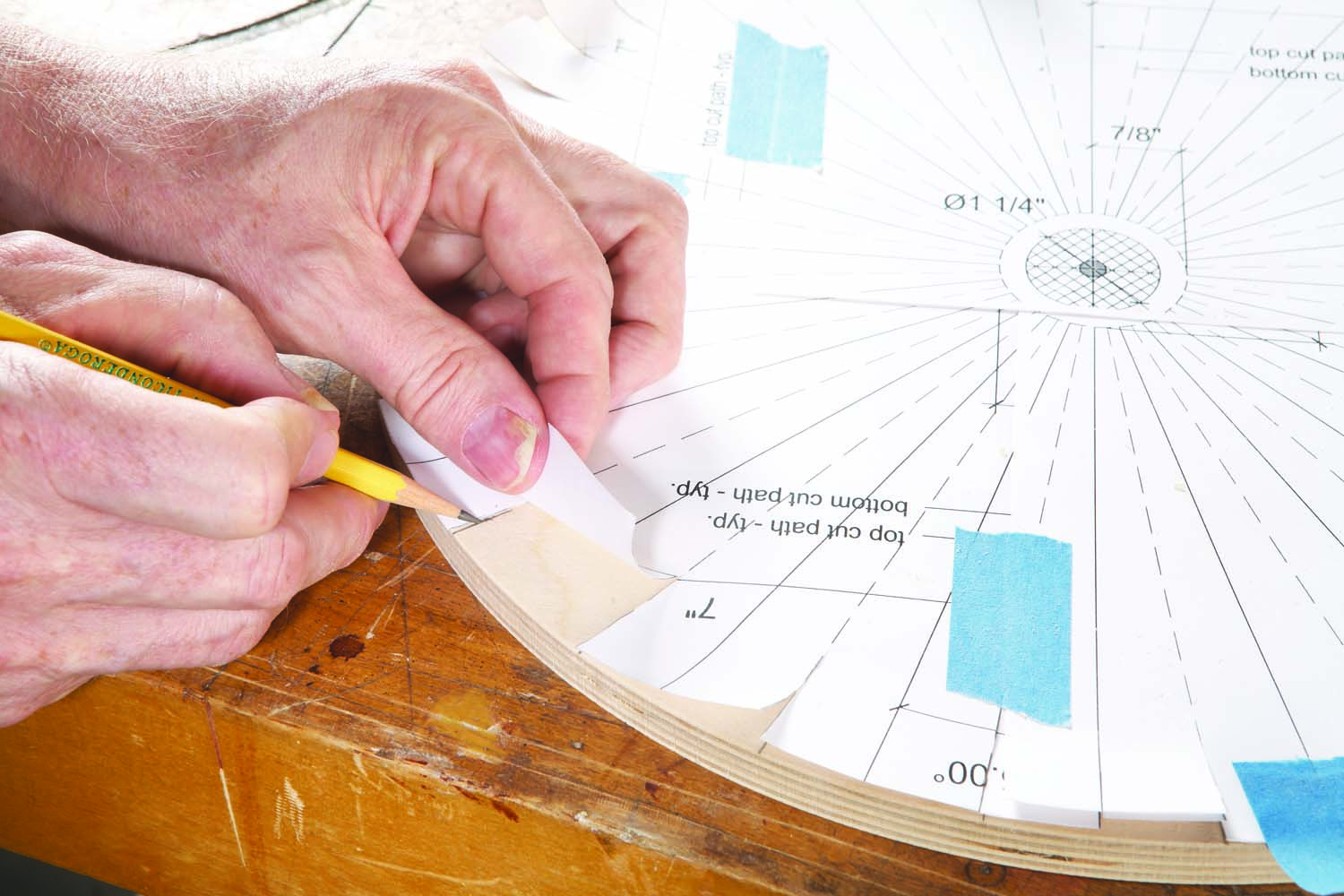
9. Mark the center of each V-groove by drawing a series of tick marks on the perimeter of the workpiece. Cut the pattern to guide your pencil.
Once you’ve marked the workpiece, place the turntable on the jig, then insert a short 3/16″ wooden dowel into the center of the workpiece. Fasten the workpiece to the turntable (Photo 10).
10. Fasten the workpiece to the turntable. The center of this pattern will be cut out later, so it’s OK to put the screws there.
Tilting the carriage
Here’s where the jig’s hinge comes into play: It allows you to tilt the carriage. When the carriage is tilted, the V-groove tapers in width and depth. To lock in the tilt, you’ll add a spacer under the carriage’s rear stretchers.
OK, so how are you going to figure out how much tilt is enough? Forget about measuring a precise angle. Just treat the taper like the slope of a roof—carpenter’s math. How much does it rise over a given length of run? Drawing a cross section of your workpiece should give you these numbers.
11. Tilt the carriage—this will cause the V-grooves to be tapered. Use a simple angle gauge that duplicates the exact rise and run of the taper. To lock in this angle, place a spacer board under the rear stretchers.
Once you know the rise and run, build a little angle-setting gauge that incorporates them (Fig. B), then place it under the carriage (Photo 11). Slide the gauge back and forth until the carriage rests on both of the “rise” pieces, then make a spacer (K) to support the rear stretchers. (Be sure to clamp the stretchers and spacer to the base before routing.) When you make some practice cuts, you can fine-tune the carriage’s tilt by adding shims under the spacer or by reducing the spacer’s thickness.
Setting up the router
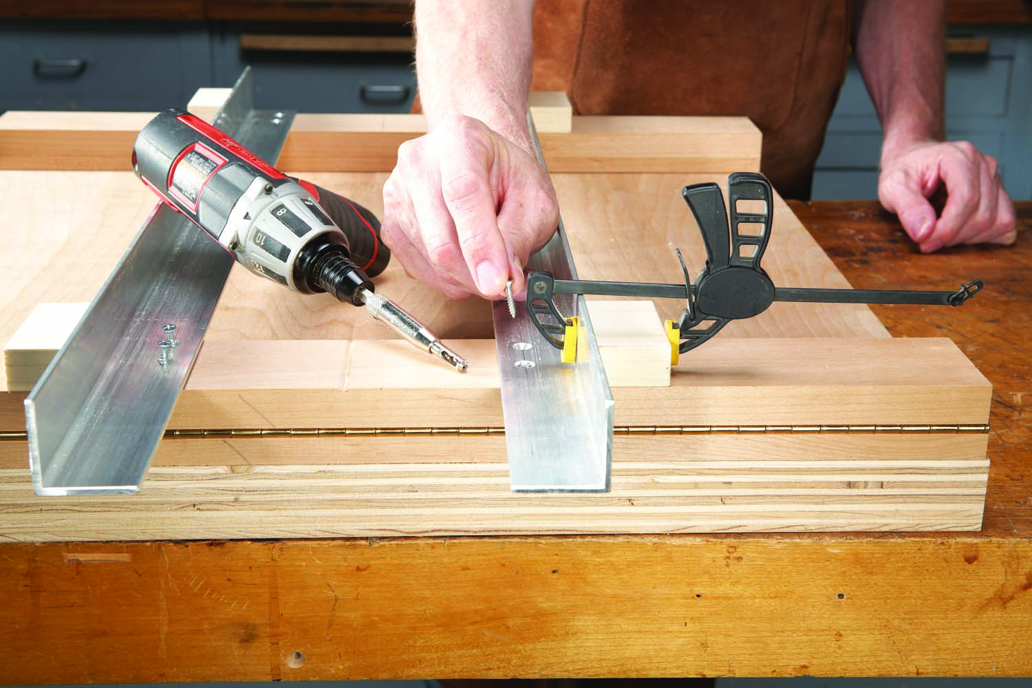
It’s time to take a test run. First, you’ll need to make some stops (L) to limit the router’s travel. Angle the front edge of the stops to prevent dust from catching in the corners.
12. Clamp two stop blocks to the carriage in order to limit router’s travel up and down the rails.
To position the stops, place the router in the carriage, then slide the router forward as far as you’ll want it to go. (I drew a circle on the workpiece to indicate the starting points of the V-grooves.) Clamp one stop against the router’s plate (Photo 12). Pull back the router until the bit clears the workpiece, then clamp the other stop in place. This stop will prevent you from inadvertently routing into the front stretchers.
13. Determine the router’s maximum depth of cut. Position the router so that the bit is centered on the inner circle of the workpiece. Plunge the bit until its tip contacts the wood. These practice cuts show the V-grooves tapering to nothing.
Next, set the router’s maximum depth of cut. For this pattern, I just lowered the router until the bit touched the penciled inner circle (Photo 13). I don’t intend to make a full-depth cut in one pass, so I also adjusted the plunge router’s turret to make two shallower passes first.

14. Make a spacer block for indexing the workpiece each time you rotate it. Line up the end of the block with each tick mark, then lock the turntable with toggle clamps.
Position the turntable so that one of the tick marks on the workpiece is aligned with the centerline routed into the front stretchers (Photo 14). You can eyeball this, but there’s a better way: Use an indexing block. Cut the block so its length is the exact distance between one of the carriage’s rails and the stretcher’s centerline. To use the block, butt one end against the carriage, then rotate the turntable until one of the tick marks lines up with the block’s other end. Lock the turntable with the toggle clamps and you’re ready to rout.
Here are some supplies and tools we find essential in our everyday work around the shop. We may receive a commission from sales referred by our links; however, we have carefully selected these products for their usefulness and quality.