We may receive a commission when you use our affiliate links. However, this does not impact our recommendations.
As easy to use as it is to build.
Editor’s note: This article originally appeared in the March 2008 issue of American Woodworker. Adjusting for inflation, the correct title would be “$121.49 Router Table”
Sometimes, less really is more. Take router tables for instance. It’s not at all difficult to ring up a $1000 tab for a manufactured router table, complete with a new router, loaded with convenience, durability, adjustability, and precision.
But to me, the compelling thing about a router table is that it converts a portable power tool into a stationary power tool and thus expands its utility and versatility.
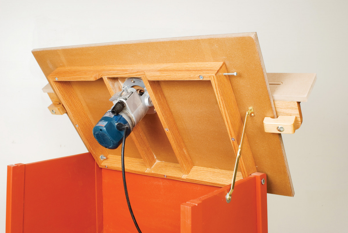
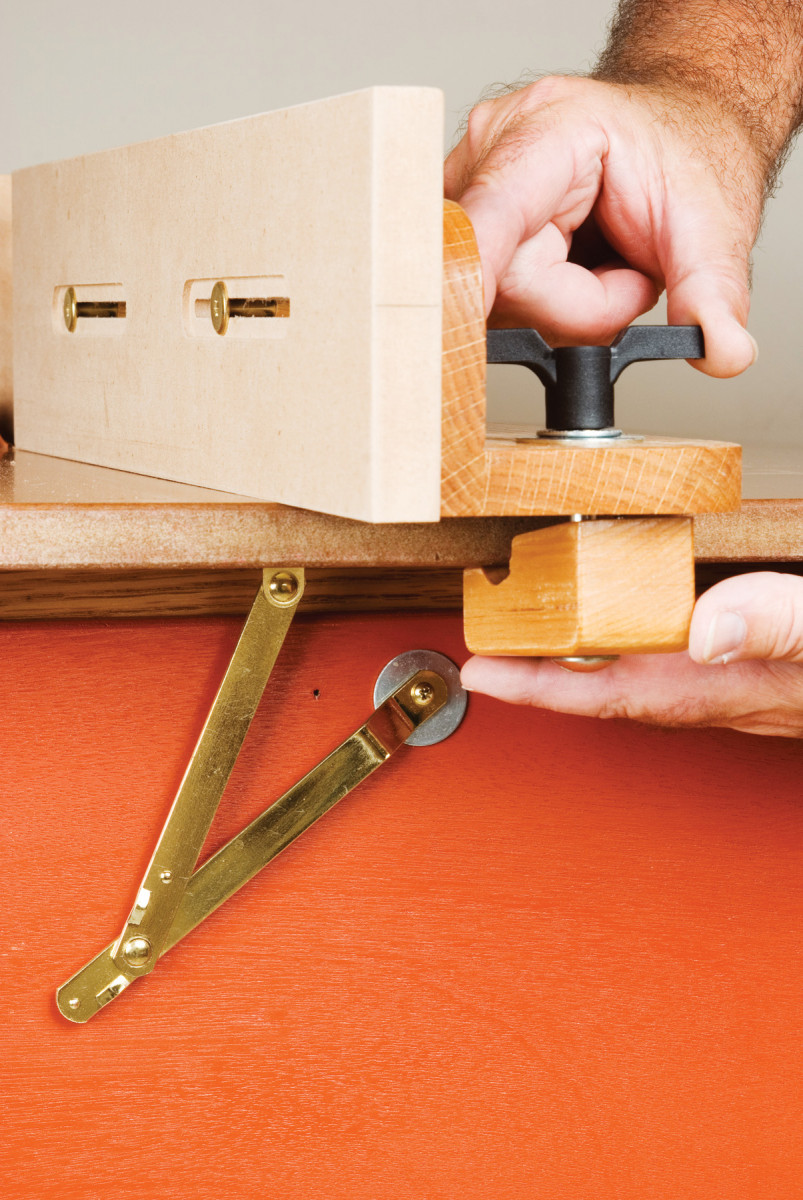
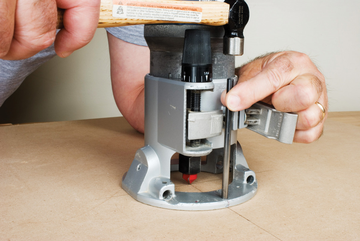
With the tabletop tilted up, it’s easy to pop open the base clamp and pull the motor to change bits.
A router table can be simple and quite inexpensive to make without sacrificing functionality. A basic table can be just as versatile, accurate and easy to use as one of those $1000 grandees but cost far less.
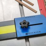
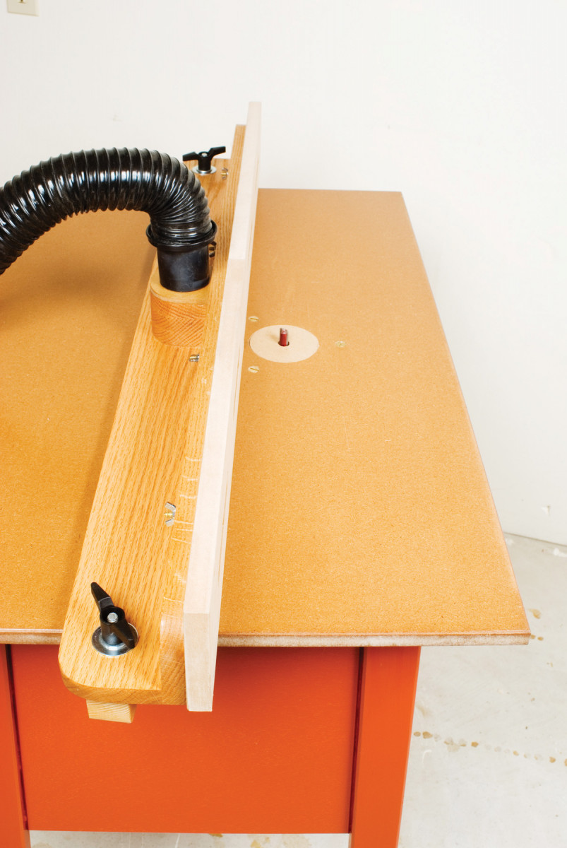
Integral clamps stay with the fence, yet allow it to be adjusted one end at a time. Big plastic wing nuts are easy on the fingers.
I’ve just finished a $100 router table (excluding the router). I bought most of the materials and hardware at a local home center.
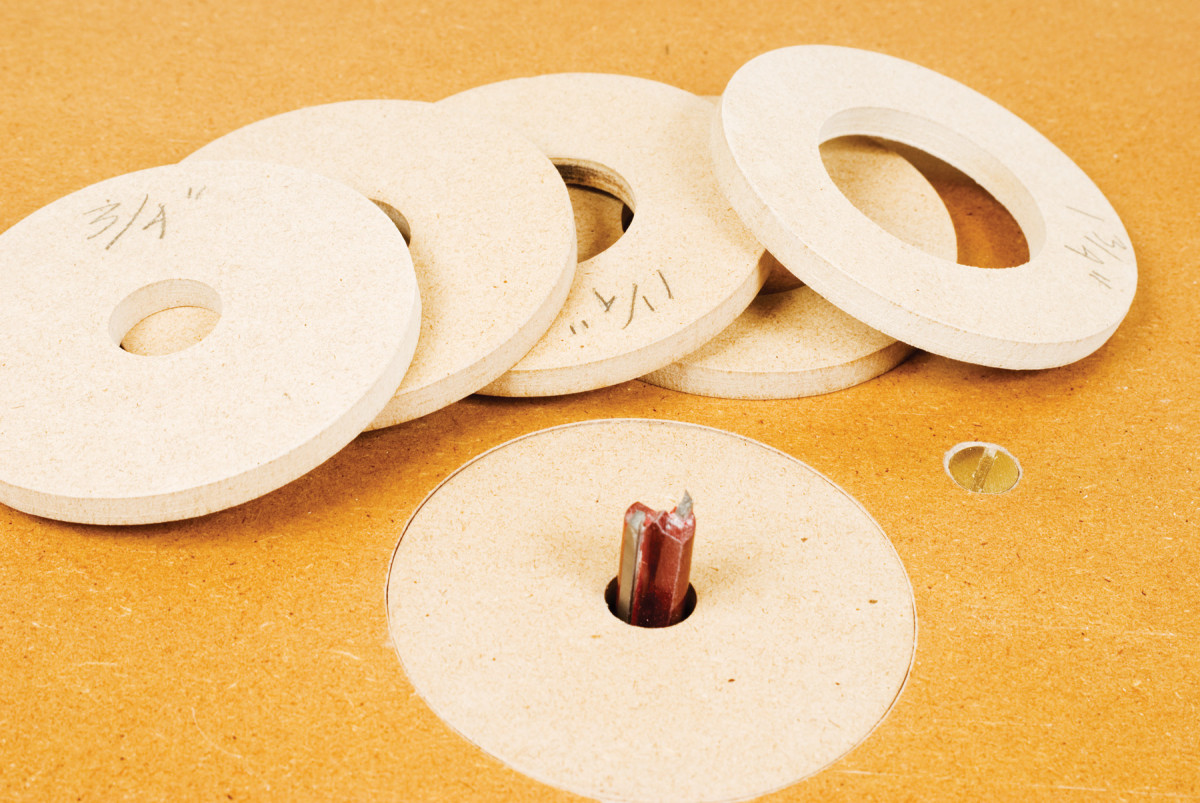
Shop made reducers improve the safety of your router table at virtually no cost.
There’s no router mounting plate to buy; the router attaches directly to the hinged top.
FEATURE PACKED
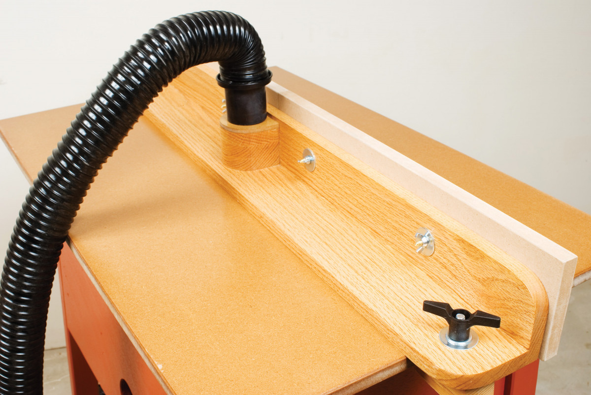
Dust collection is built-in to the fence and under the table.
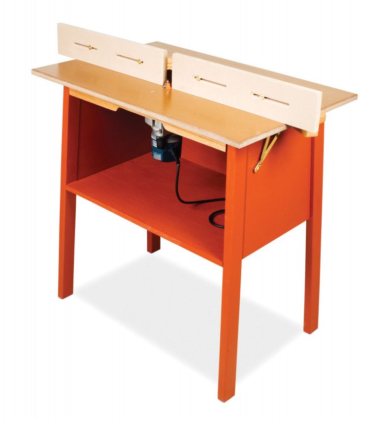
This is no bare-bones table, it’s packed with great features such as an easy to adjust zero-clearance fence with sacrificial faces, an offset router mounting that allows you to use more of the table for work support, table inserts to accommodate different bit sizes, a tilt top for easy access to the router and quick bit changes (even with a plunge router), and built-in dust collection.
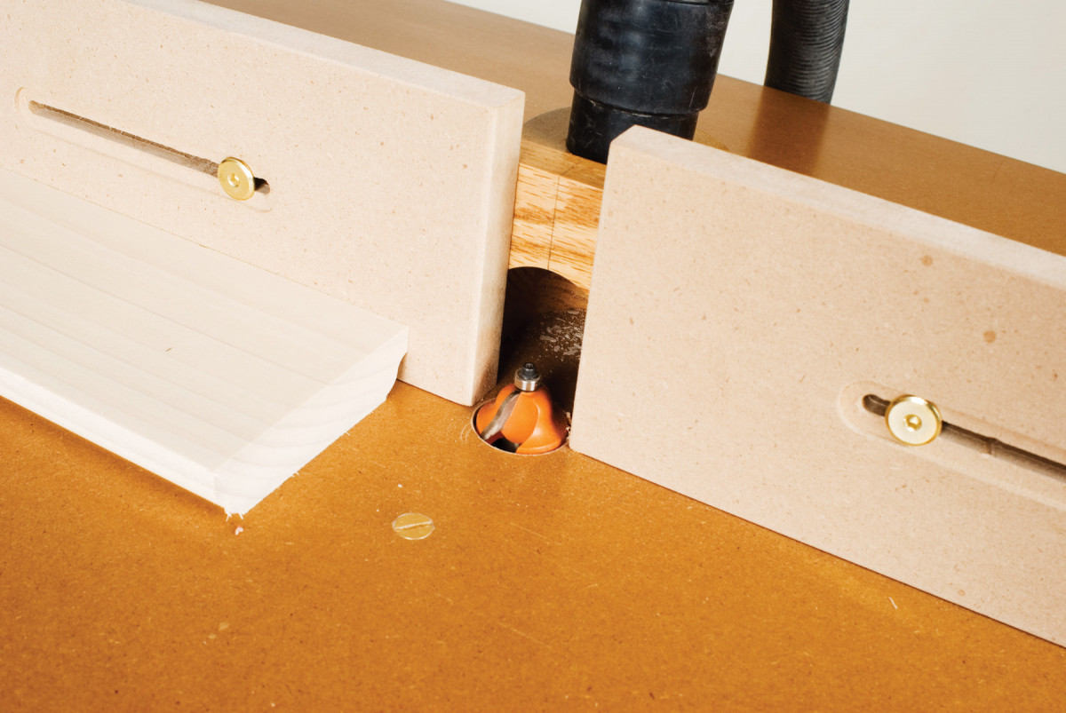
Adjustable fence faces are counterbored on both side giving you four faces that can be turned over as the ends get chewed up.
Of course there’s a host of enhancements to the basic router table including enhanced dust collection below the table, a front-mounted switch, and even bit storage.
An offset router location puts the router close to you for the lion’s share of router-table operations.
All these add-ons are covered at the end of the article.
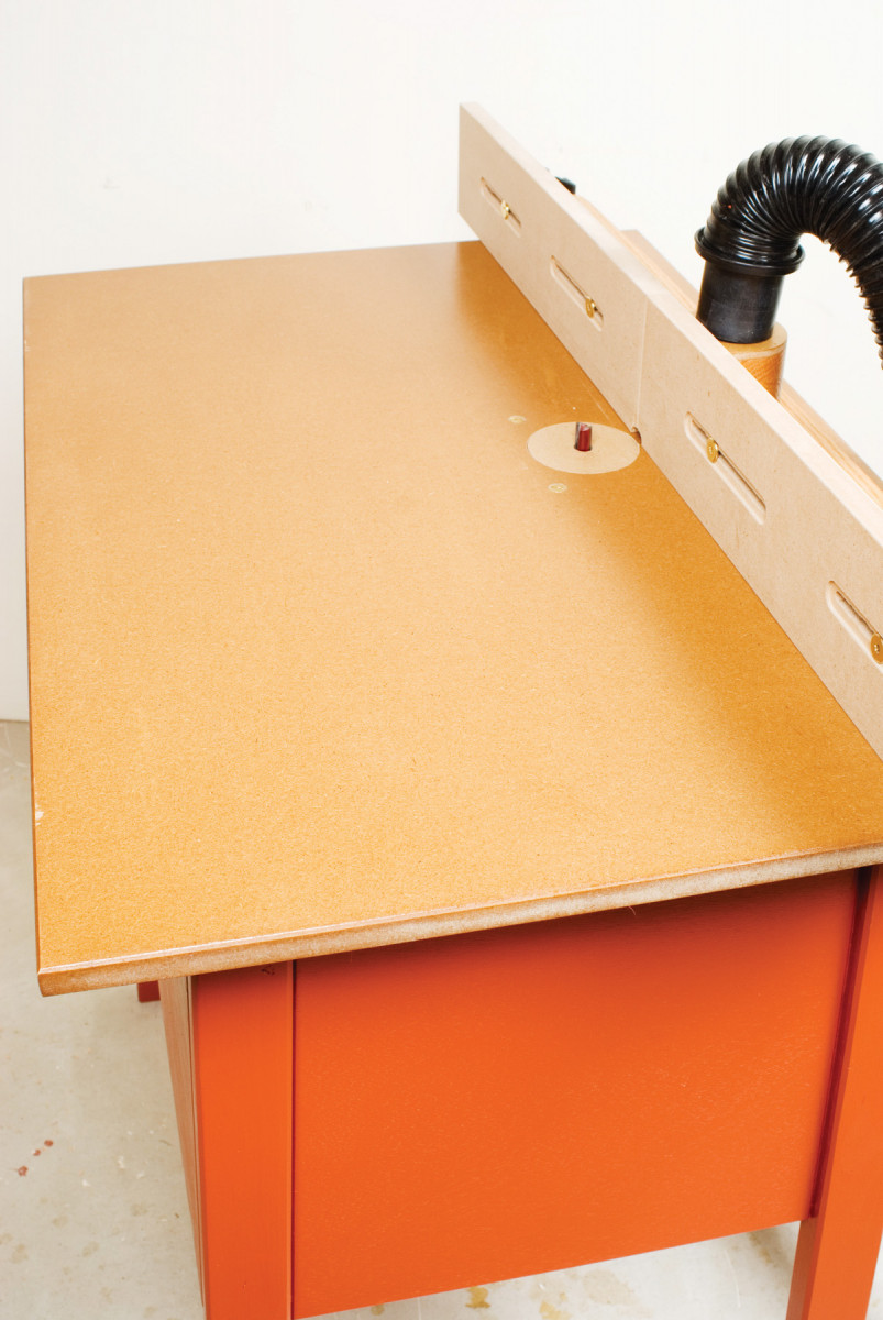
Flip the fence around to the back side of the top for a big offset. The extra support is ideal for panel raising.
100$ Router Table Cut List
Overall Dimensions: 24″ D x 36″ W x 34-1/2″H
Part Qty. Dimensions Material
A Tabletop 1 3/4″ x 24″ x 36″ MDF
B Frame front/back 2 3/4″ x 2 1/2″ x 27 1/2″ hardwood
C Frame ends 2 3/4″ x 2 1/2″ x 17 1/8″ hardwood
D Stretchers 2 3/4″ x 1 3/4″ x 17 1/8″ hardwood
E Legs 4 1 1/4″ x 2 1/4″ x 33″ 2 x 6
F Side aprons 2 3/4″ x 16″ x 15 3/16″ plywood1
G Back apron 1 3/4″ x 13 1/8″ x 29 3/16″ plywood1
H Bottom 1 3/4″ x 18 15/16″ x 29 3/16″ plywood2
J Edge band 1 3/4″ x 1/4″ x 29 3/16″ 2 x 63
K Fence base 1 3/4″ x 3 1/2″ x 42″ hardwood
L Fixed face 1 3/4″ x 3 1/2″ x 42″ hardwood
M Sliding faces 2 3/4″ x 4″ x 24″ MDF
N Dust pickup block 3 3/4″ x 3 1/2″ x 3 1/2″ hardwood4
P Dust pickup cap 1 1/4″ x 3 1/2″ x 3 1/2″ 1/4-in. MDF
Q Clamp jaws 2 1 1/2″ x 2 1/2″ x 3 1/2″ 2 x 63
1 Miter ends at 87°
2 Bevel edges at 3°
3 Cut from scrap
4 Stack and glue
BUILD THE BASE
Cut the leg blanks (F) oversize from 2×6 lumber that’s been seasoned in your shop for two weeks or more.
Cut 3-degree compound miters on the tops and bottoms of the legs. All the cuts are made with the head tilted 3- degrees. Divide the legs into 2-pairs consisting of one front and one back leg.
Cut the plywood panels (G-J). First, crosscut a 30-3/4-in. piece from a sheet of plywood. Rip it into a 19- in. wide piece for the bottom, a 13-in. wide piece for the back apron, and a 16-in. wide piece for the side aprons. Crosscut the side-aprons piece in half.
Tilt the tablesaw blade 3-degrees and cut bevel on all four edges of the bottom panel, reducing it to its final length and 1/8-in. shy of its final width.
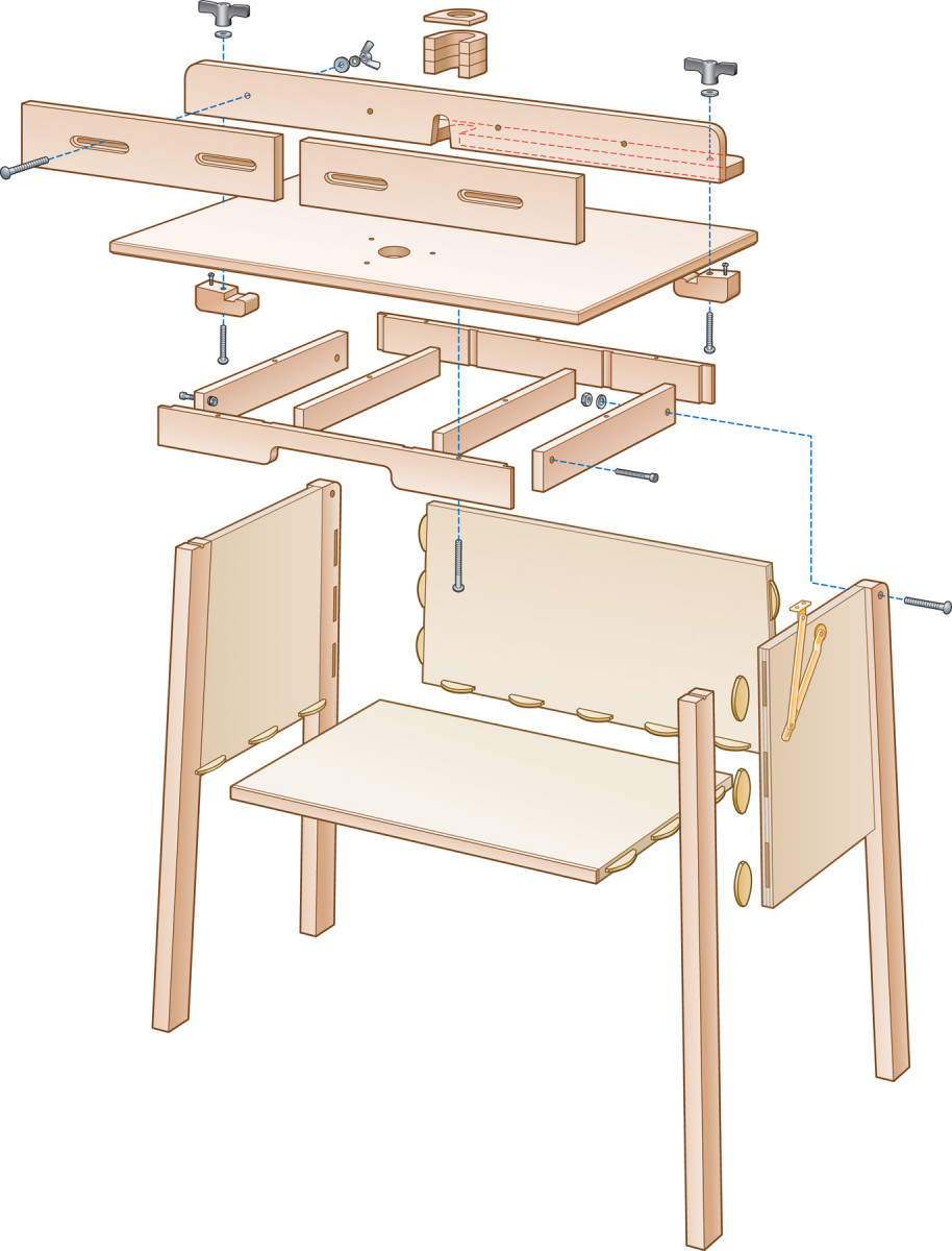
FIGURE A EXPLODED VIEW
Glue a 1/8-in. strip of solid wood to the front edge of the bottom panel. Trim flush after the glue’s dried.
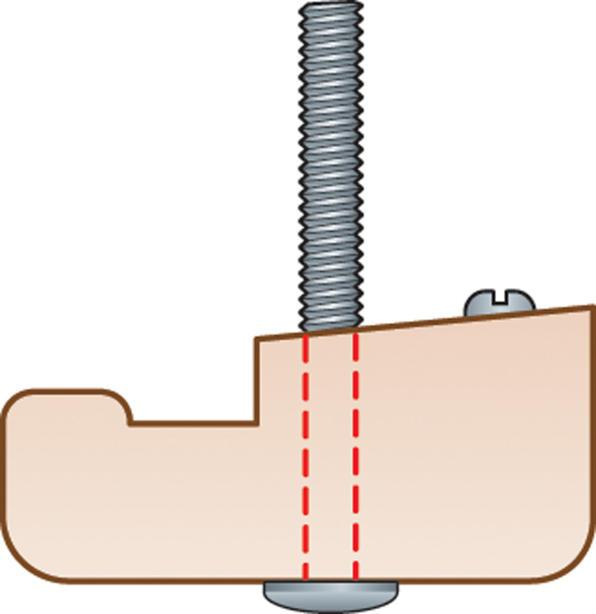
DETAIL 1 CLAMP BLOCK
Return the tablesaw blade to 90- degrees and set the miter gauge to 3- degrees. Cut the tapered ends on the side and back panels.
Lay out marks for biscuit slots on the ends of the side and back aprons. Align the legs with the aprons and transfer the marks.
1. Glue and clamp the two side assemblies. Use the offcuts from tapering the aprons as cauls so the clamps have parallel surfaces to address.
Lay out biscuit slots on the bottom shelf and transfer them to the bottom edge of the aprons.
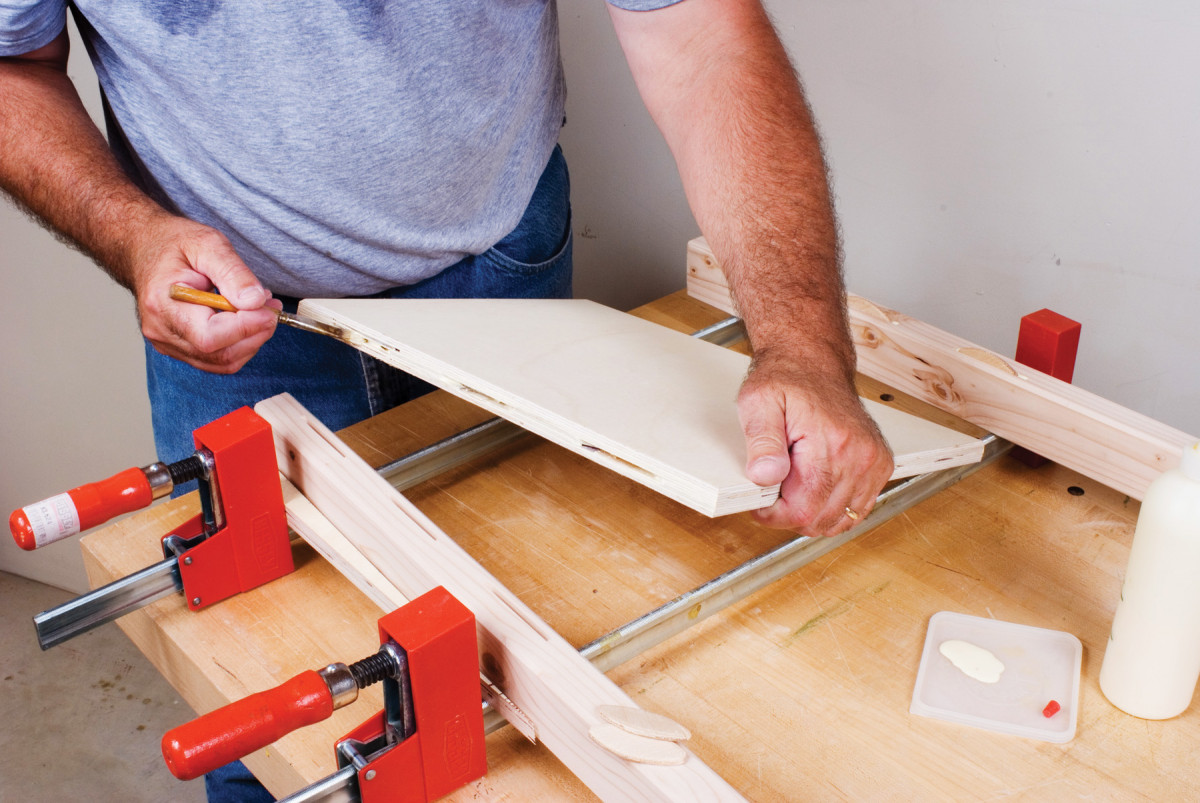
Cut the biscuit slots. Set the joiner’s fence to 87-degrees to slot the beveled edges of the bottom panel. Glue and clamp the two side assemblies together (Photo 1) as well as the back and bottom panel assembly.
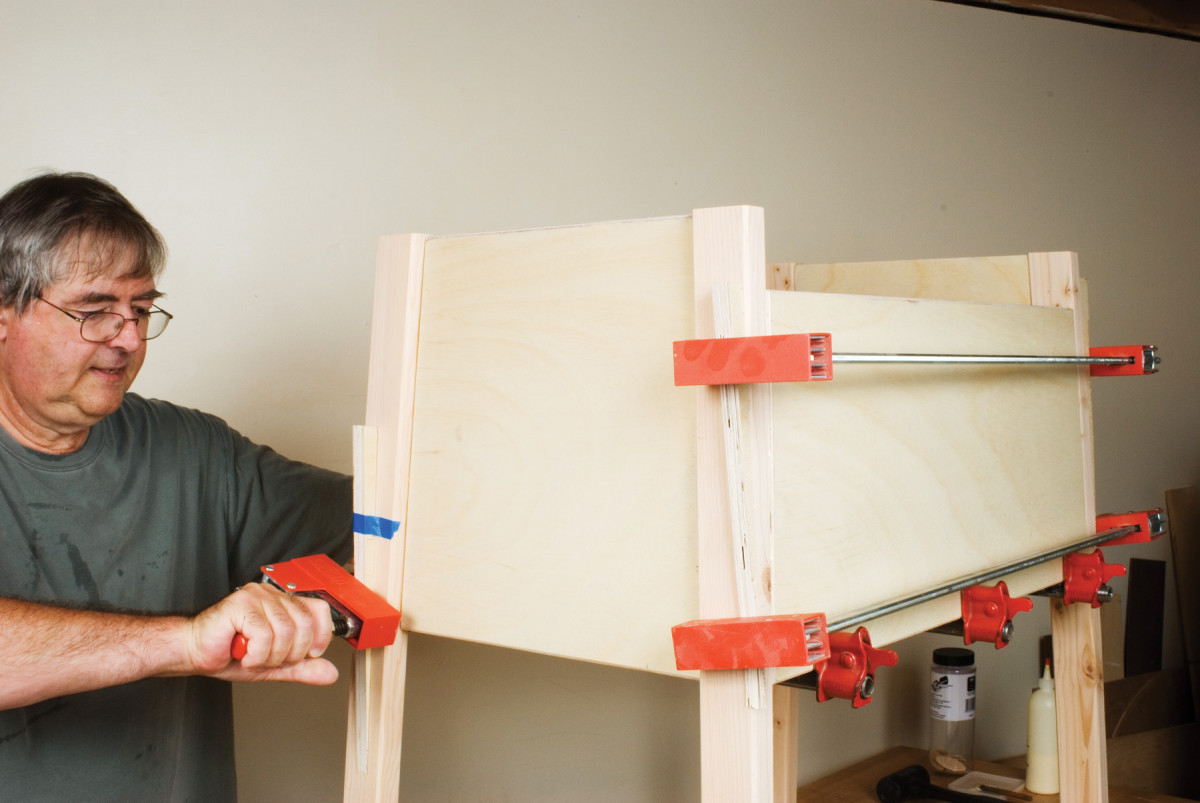
2. Glue and clamp the side assemblies to the back apron and bottom shelf. Use the tapered cauls to keep the clamps from slipping as they’re tightened.
Join the two leg assemblies to the back and bottom panel assembly (Photo 2). Use masking tape to attach the tapered scraps from the panels to the legs so clamps will have parallel bearing surfaces.
BUILD THE TABLETOP
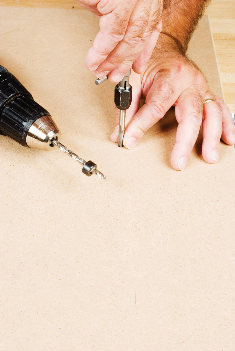
3. Mark the locations of the router mounting screws on the top with a transfer punch—a.k.a. a spotter.
Cut the tabletop panel (A). Chamfer all four edges, top and bottom, to minimize chipping.
Lay out the bit hole location on the top (Fig. A.).
Install a V-groove bit and park the router with the bit on the penciled crosshair. Orient the router exactly the way you want it—handles side-toside, front-to-back, or on a diagonal. Mark the center points for the mounting screws (Photo 3).
Drill and countersink the mounting holes in the top. Mount the router to the tabletop.
4. Transfer the mounting-bolt holes in the framework to the MDF top using a transfer punch.
Cut the support frame parts (B, C and D). Cut rabbets in the ends of the front and back pieces.
Dry assemble the frame on the tabletop. Use your router base to determine the spacing between the stretchers . Lay out the dadoes and rabbets in the front and back frame members as well as the cutout in the front.
Machine the frant and back rails. Then, assemble the frame on a surface you know is flat.
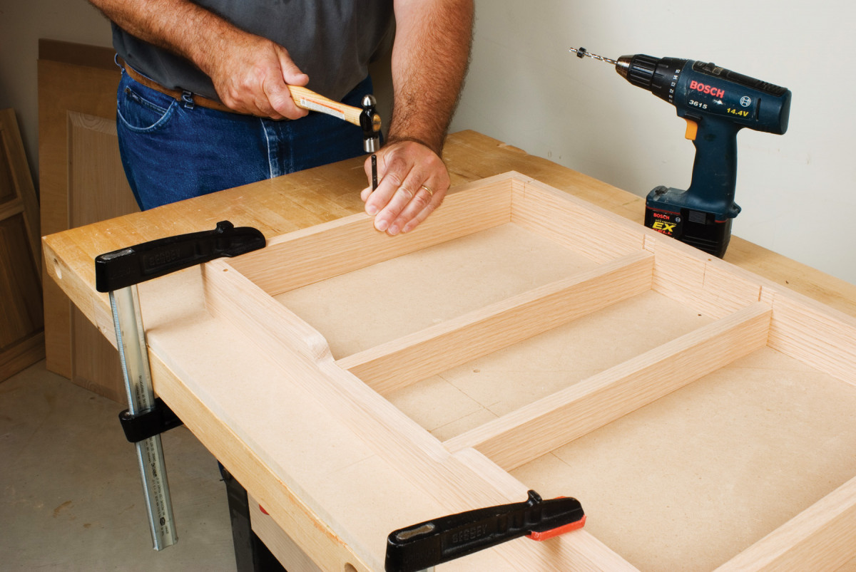
Drill 1/4-in. holes though the frame edges. Set the frame on the tabletop and transfer the hole locations to the tabletop (Photo 4).
5. Cut threads in the top with a 1/4″-20 tap. Use a 13/64-in. bit to drill a 5/8-in. deep stopped hole at each mark, first. Make sure you clear all the chips from the holes. Then turn the tap into the hole until it bottoms out.
Drill and tap stopped holes in the MDF for 1/4 – 20 machine screws (Photo 5). Threaded MDF has better holding power than wood screws driven into pilot holes.
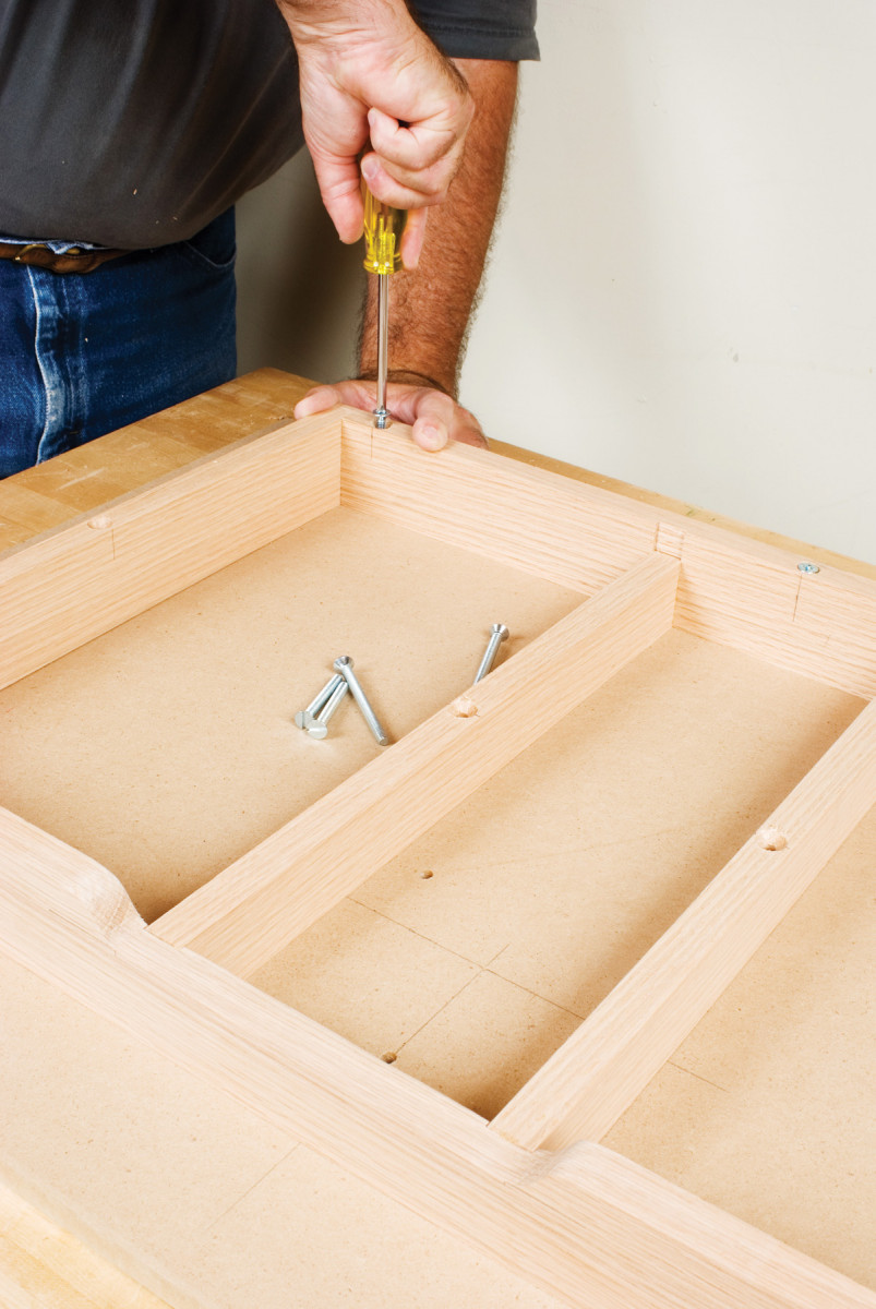
6. Reposition the frame on the tabletop and fasten it with 1/4″-20 flathead machine screws. I used seven 3″-long screws in the perimeter frame members and two 2″-long screws in the stretchers.
Mount the tabletop to the frame (Photo 6). You could glue the frame, but if you eever changed routers, you’d need to build a new top.
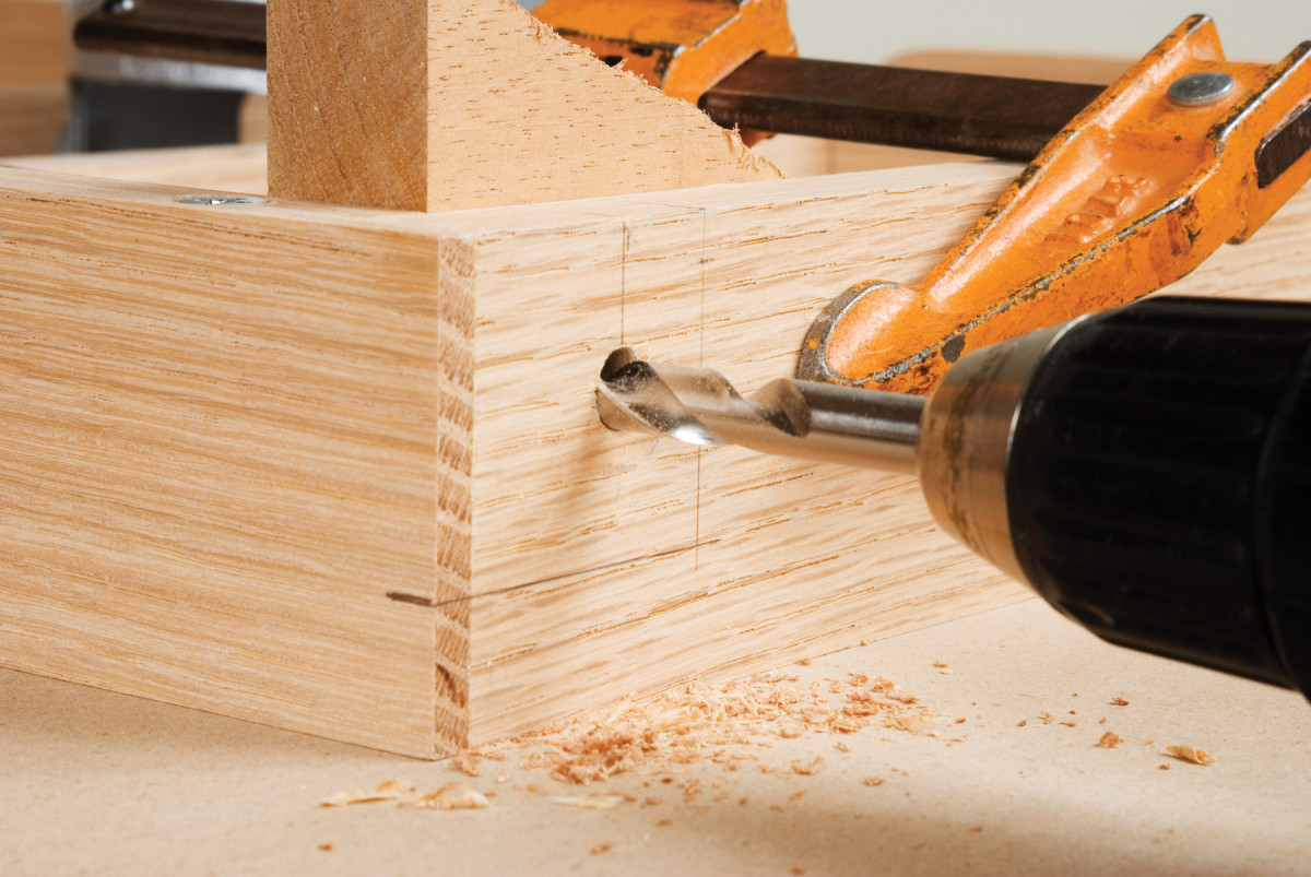
7. Lay out and drill the two 3/8-in. hinge-bolt holes in the frame. Clamp a backup scrap to the inside of the frame to prevent blowout.
Drill the holes for the hinge bolts in the frame (Photo 7, Fig. A). Cut threads in the rest bolt holes for 1/4 – 20 bolts.
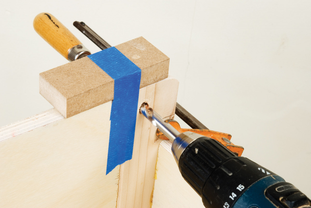
8. Drill hinge holes through the backlegs. Tape 3/4″ shims to the top edges of the stand and rest the tabletop on them. Use a transfer punch to mark the hinge-bolt hole locations on the back legs, then drill.
Set the top on the stand. Use shims between the top edge of the stand and the MDF top. This keeps the top floating above the stand so all the weight from the top is carried by the framework underneath.
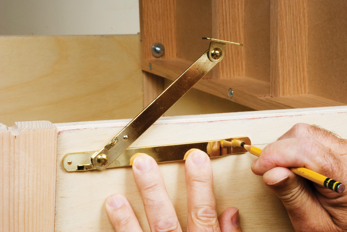
9. Mount the folding stay to the stand first. Measure down 1-in. from the stand’s top edge and scribe a line. Hold the folded stay on the line so it clears the front leg and mark the screw location.
Transfer the hinge boltholes from the top frame to the back legs of the stand. Drill the hingebolt holes through the back legs (Photo 8). Install the hinge bolts and rest bolts.
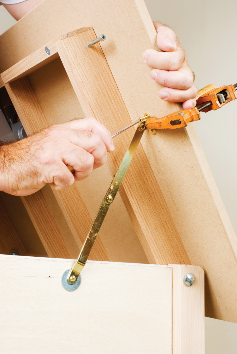
10. Attach the stay to the top. Hold the stay in position with a clamp. You decide the degree of tilt that suits you.
Mount the stay to hold the top open (Photo 9 and 10).
BUILD THE FENCE
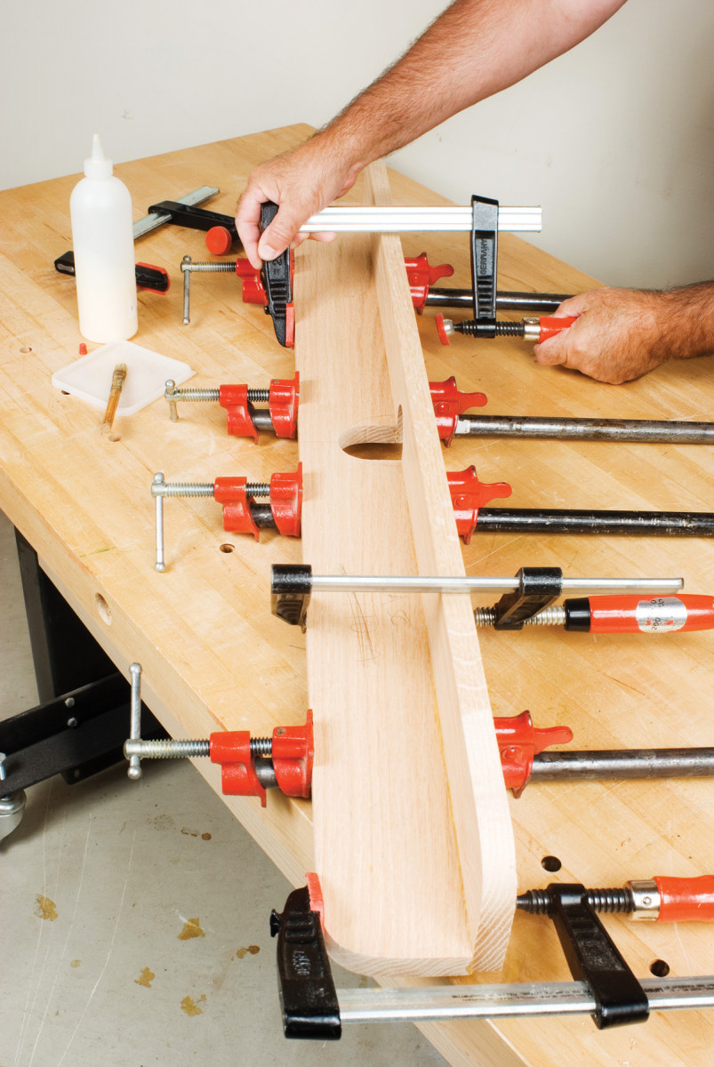
11. Glue and clamp the base and fixed face together.
Cut the fence base (L) and fixed face (M).
Cut the bit opening in the two fence pieces. Bore a 2-1/4-in. hole centered 1-in. from an edge using a Forstner bit or a holesaw. From the near edge, saw into the hole, transforming it into a U-shaped notch.
Assemble the base and fence. Glue the edge of the base to the upright’s face (Photo 11).
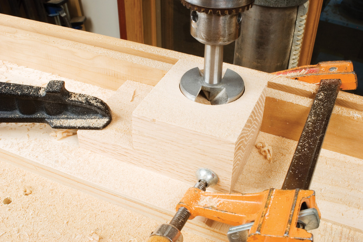
12. Bore a 2-1/4″ hole through the dust pickup housing block with a Forstner bit or holesaw.
Round off the outside corners at the ends of the fence on a band saw, then sand smooth.
Cut and glue-laminate scraps of hardwood to form the dust-pickup block (P).
Bore a 2-1/4-in. hole through the block (Photo 12).
On the bandsaw, cut a U-shaped hole and the outside profile of the block. Sand the sawed surface smooth.
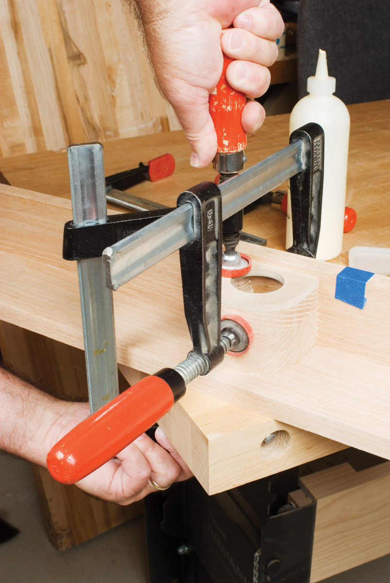
13. Glue and clamp the dust pickup to the fence. Tape scrap across the openings in the face to provide a bearing surface for the clamps.
Cut the dust pickup’s cap (Q). Bore a hole to fit your dust collector hose. Glue the cap to the dust pickup and the pickup to the fence (Photo 13).
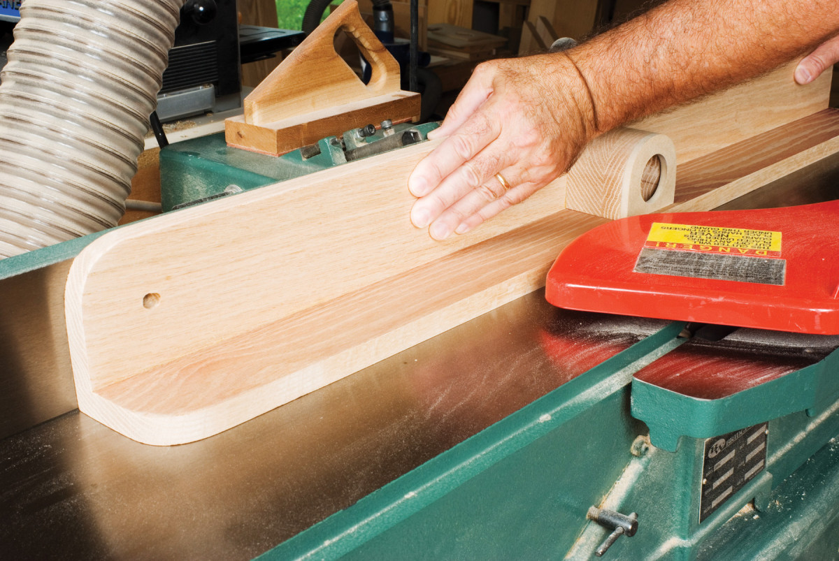
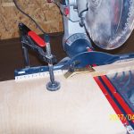
14. Joint the glued-up fence to square the face to the base. Joint the base surface first to flatten it; then joint the fence face with the base against the jointer fence.
Square the face of the fence to the base on a jointer (Photo 14)
Cut two clamp jaws (R) (Fig. A, Detail 1) from scraps. Sand the faces and edges.
Lay out and drill mounting bolt holes in the fence base and the clamp jaws (Fig. A).
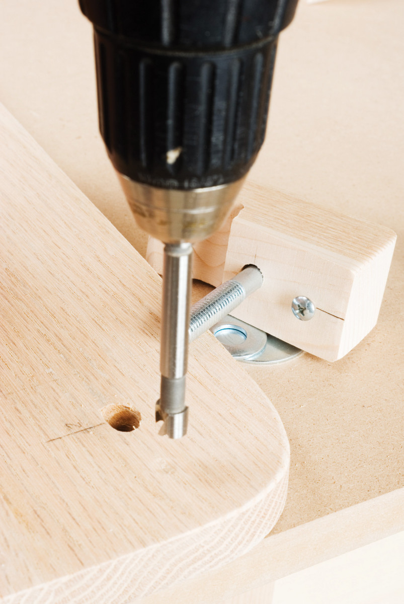
15. Drill a stopped hole in the fence base that will holdthe alignment screw head and keep the clamp block aligned perpendicular to the tabletop. To mark the hole, tighten the clamp block in place so the alignment screw head dents the base.
Drive a roundhead or panhead screw into the block near the bolt hole to act as an alignment screw. Drill oversize holes for the bolts in the fence base and add a shallow hole to house the alignment screw head (Photo 15).
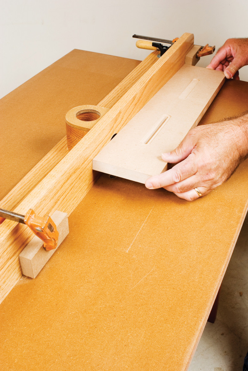
16. Use the fence to cut the countersunk grooves in the adjustable faces.
Make the adjustable facings (N) from pieces of leftover MDF. Cut faces to size, then use your new router table to rout stopped slots for the mounting bolts (Photo 16).
Drill mounting holes for the adjustable facings in the fence (Fig. A).
Use your largest bit to rout the opening in the tabletop. Cut a narrow rabbet around the opening, its depth matching the thickness of the material you use for the inserts.
Cut one insert that fits nice and snug, and use it as a pattern for routing out a half-dozen more. When you put a hole in an insert, label its diameter.
Enhancement 1
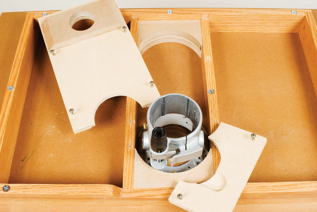
A) BELOW THE TABLE DUST COLLECTION CAPTURES FUGITIVE DUST
Capturing all the chips and dust generated by router-table operations is a tough proposition. A fence-mounted pickup is important, but without a pickup under the table, a lot of the dust will escape capture.
You can use the support frame’s stretchers as the basis of a very effective dust chute. Make a twopiece cover from scraps of MDF or plywood. Insert rounded baffles to close off corners where dust gets trapped. Fit the caps as close as possible around the router base and drill a hole for a dust-hose connector (Photo A).
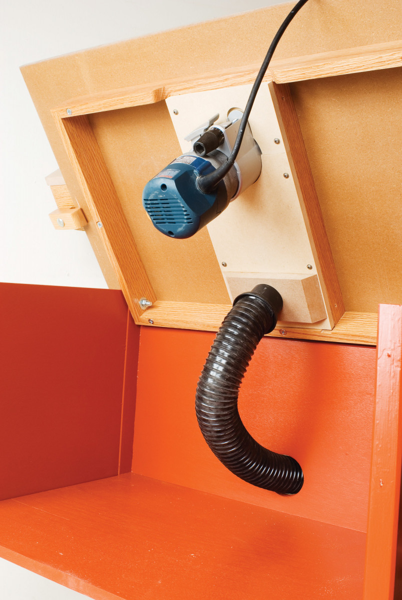
B)
Extend a hose from this under-the-table channel and splice it into the hose from the fence-mounted pickup with a wye fitting. Leave enough slack in the hose to permit tilting the tabletop (Photo B).
Enhancement 2
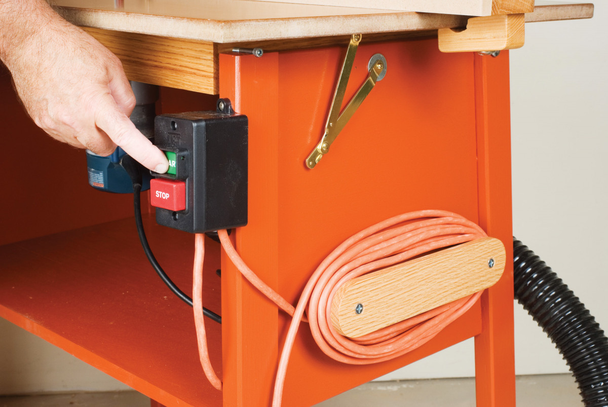
EXTERNAL SWITCH ADDS SAFETY AND CONVENIENCE
Powering up a table-mounted router with the router switch is usually a nuisance. And lots of us are uneasy about fumbling for an out-of-sight switch in an emergency. So a front-mounted switch is a worthwhile addition to any router table. I wired the switch to an extension cord. The cord wrap is made from hardwood scraps.
Enhancement 3
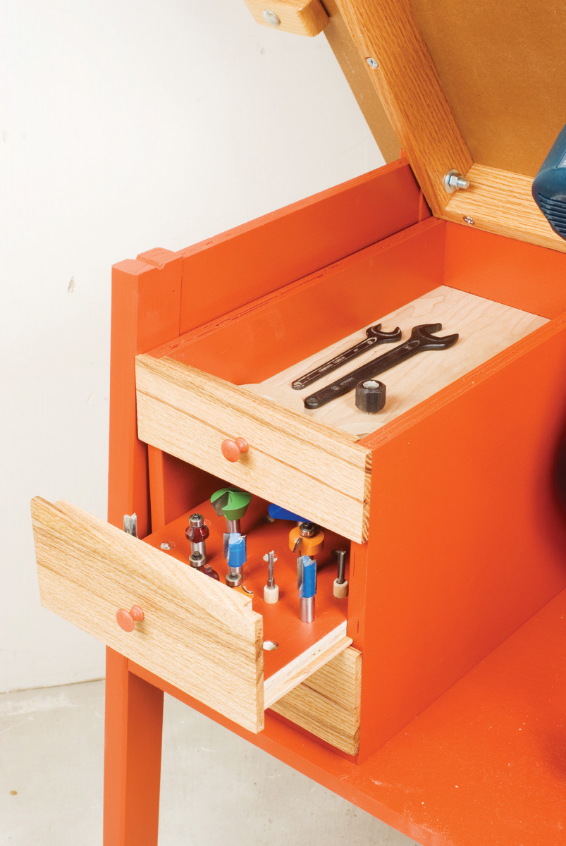
CONVENIENT ONBOARD BIT STORAGE
Bit storage is a practical addition to the table, and there’s enough plywood left to construct a small box for two or three drawers. The drawer fronts require an additional 4-ft. piece of 1-in. x 4-in. oak. The drawer bottoms are 1/4″ plywood and are cut wide enough to fit in slots cut in the box sides.
Two drawers have the bottoms drilled for 1/2-in. and 1/4-in. shank bits; together they’ll accommodate about 80 bits. The top drawer holds wrenches, collets, bit-opening inserts, and other accessories. It is exposed when the tabletop is tilted up for easy access during bit changes.
Woodcraft, www.woodcraft.com (800) 225-1153, 2 – Wing Knobs, #85J94, $4.
Optional Upgrades:
Switch Jet, www.jettools.com, click on “Shop Parts”, # 994542 Switch, $26, # 523028 switch box, $4, # 998654, 2 – strain relievers, $4, Hardware Store, 12/4 extension cord, $12
Dust Collection Woodcraft, www.woodcraft.com (800) 225-1153, 2-1/2-in. x 10-ft. hose with 2 end fittings, #128689, $16, 2 -1/2-in. Y fitting, #144282, $4, 2-1/2-in. end fitting, $3.
Bit Storage 3/4-in. plywood parts cut from leftover material 1/4-in. plywood for drawer bottoms 3/4-in. oak for drawer fronts and pulls
Here are some supplies and tools we find essential in our everyday work around the shop. We may receive a commission from sales referred by our links; however, we have carefully selected these products for their usefulness and quality.