We may receive a commission when you use our affiliate links. However, this does not impact our recommendations.

Make bent laminations on a big scale.
One sweeping curve, 18-ft. long: that’s the essence of this dramatic stand. Making up that curve are dozens of thin pieces of construction-grade redwood, all glued together to make an extremely strong beam.
 The beam is composed of three identical pieces: two are butted end-toend to make the lower curve, while a third piece bolted on top binds the two together.
 I’ll show you how to build an inexpensive bending form to create the three sections, how to cut the laminations and glue them together, and how to make the beam’s edges smooth and even.
 You’ll need twelve 10-ft. redwood 2x4s to make the laminations. (You could substitute western red cedar, as long as the pieces are fairly free of knots.) You’ll also need about 62 lineal feet of 2×4’s, including one 14-footer, to make the stand’s other parts.
BUILD THE BENDING FORM

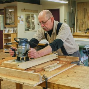
1. The stand’s curved beams are made of many thin laminations, glued together over a bending form. Begin by laying out the form’s arc on a large sheet of hardboard siding material, using a long board as a trammel.
To build the form, you’ll need one 4-ft. x 9-ft. sheet of 1/2-in.-thick house siding (hardboard or plywood). You’ll also need two 1x4s (one 10-footer and one 12-footer) to make a very large beam compass, also known as a trammel. Screw or clamp the 10-footer to the siding (Photo 1 and Fig. B).

2. Cut the hardboard using a jigsaw, then fasten pairs of short 2×4 blocks along the entire curve.
Attach the 12-ft. 1×4 to the end of the 10-ft. 1×4 with a bolt and nut, so the 12-footer will pivot as a swinging arm. Drill a hole to fit a pencil in the other end of the arm. Screw a short piece of 1×4 to the bottom of the arm, just inside the pencil hole, so the arm glides easily across the siding. Draw the arc, then disassemble the trammel.
Cut the arc using a jigsaw. Screw the trammel’s 10-footer to the long, straight side of the siding, to stiffen it.
Cut 68 blocks from 2×4 stock (you’ll need 18 lineal feet; Fig. C). Drill a 1/8-in.-dia. pilot hole in the center of each block. Glue and screw the blocks in pairs along the curved edge of the siding (Photo 2). Position each block so that the middle of its top edge is flush with the curve.

3. Screw a long piece of hardboard to the blocks. This creates a wide support for the laminations.
Cut two strips from the discarded portion of the siding. Glue and screw the strips to the top of the 2×4 blocks, butting the strips end-to-end (Photo 3). Apply wide masking tape to the form’s top surface to prevent the laminations from adhering after a glue-up. Wrap the tape over the form’s edges and down an inch on both sides.
RESAW THE LAMINATIONS

4. Resaw 10-ft.- long redwood 2×4’s into three pieces to make the laminations. Caution: You must remove your guard for this operation.
Make laminations for the beams (A, B) by resawing redwood 2x4s (Photo 4). You can do this using a bandsaw, but it’s just as easy using a tablesaw equipped with a rip blade. Attach a 3-3/4-in.-high subfence to your saw. Clamp or screw a board on top of the subfence to prevent the 2x4s from climbing up the blade. Position the subfence about 7/16 in. away from the blade in order to rip the 2×4 into three equal pieces. Raise the blade 2 in. above the table. Install a featherboard to hold the stock tight against the subfence.
Make the first cut. Turn the 2×4 over and make a second cut. Turn the 2×4 end-for end and make a third cut. This cut releases one lamination. Set the boards aside and repeat these three cuts on all of your 2x4s. Move the featherboard toward the fence and make the fourth and final cut in each board, releasing two more laminations.
Allow the laminations to acclimate in your shop for a week or so, then plane them 1/4-in. thick.
GLUE THE BEAMS

5. Plane the laminations 1/4- in. thick, then sort through the pile to select the bestlooking pieces. Use these for the top and bottom faces of each beam.
Sort through the laminations and select the most attractive pieces for the top and bottom of each beam (Photo 5). Strips with knots or defects are OK for middle pieces.

6. Spread glue on the laminations with a dense-foam roller.
Use a weatherproof glue for the laminations. I prefer Titebond III because it allows very little cold creep (which means the edges of the laminations will stay even over time). A dense-foam roller works well for spreading the glue. Keep the roller in a large, sealed plastic bag between applications, so you won’t have to wash it out every time. Select four laminations and pour glue in a wavy pattern on top of three of them. Spread the glue thick enough to obscure the wood’s grain pattern (Photo 6).
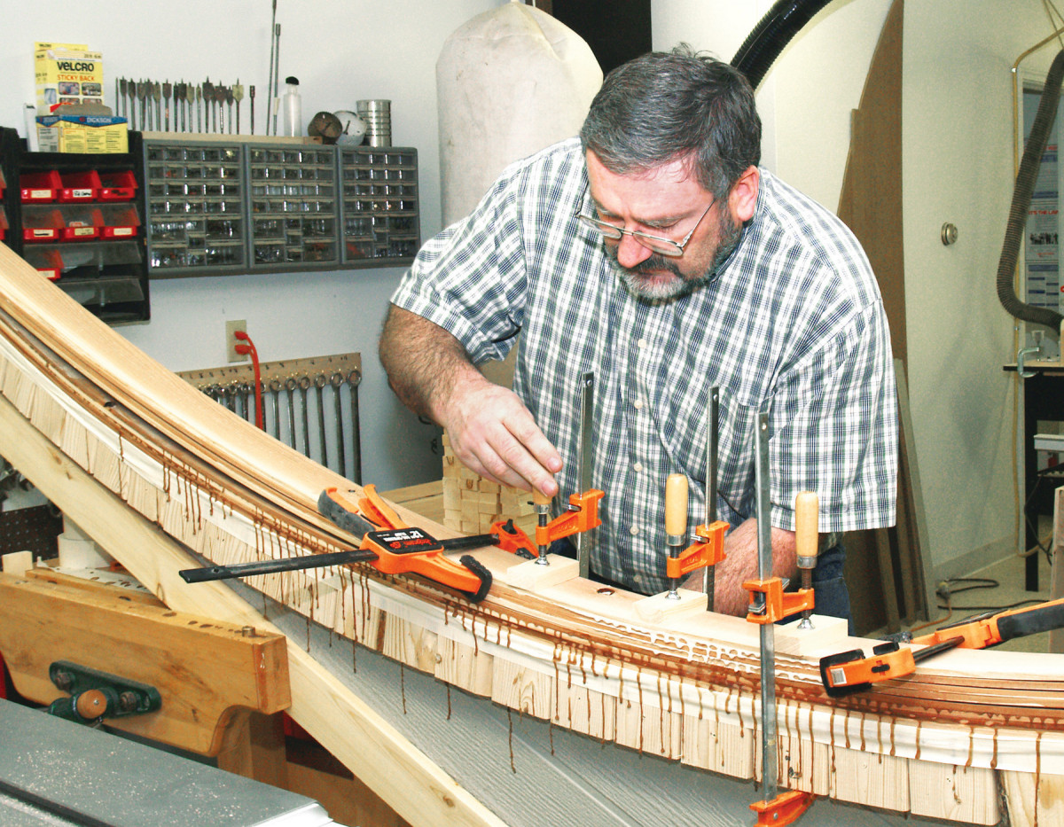
7. Clamp four laminations to the bending form, then let the glue cure. Each beam consists of twelve laminations.
Clamp the four laminations to the bending form (Photo 7). Place blocks under each clamp head to avoid denting the top lamination. Before applying final pressure, align the laminations with quick-action ratcheting clamps. Start at the center of the curve and work towards each end, placing a clamp on every other 2×4 block attached to the form. Alternate the clamps side-to-side to evenly distribute pressure. Inspect for gaps between the laminations before you let the assembly dry overnight. Use more clamps to close gaps as needed.
Repeat this procedure three times to complete one beam, which contains a total of twelve laminations. To remove the beam from the form, score through the glue run-off with a utility knife and push the beam sideways. Avoid prying it up. Glue together two more beams the same width and length.
DRESS THE BEAMS

8. Make three beams. Level and square one side of each beam using a jack plane. Then mill the beams to final thickness using a planer.
Use a paint scraper and jack plane to remove the dried glue from one side of each beam. Make sure that the side is square to the top (Photo 8). Scrape glue from the opposite side and run the beams through the planer. Make all three beams the same thickness.
Cut both ends of two beams at 90 degrees using a miter saw with added outboard support. These pieces become the bottom beams (A). Cut the other beam’s ends at 45 degrees. This piece becomes the top beam (B).

9. The stand’s bottom curve consists of two beams butted end-to-end, with the third beam fastened on top. Clamp the top beam to one of the bottom beams and drill holes through both pieces. Fasten the beams with carriage bolts.
Mark the center of the top beam and clamp it to one of the bottom beams (Fig. A). Use a 3/8-in.-dia. extra-long drill bit to bore four holes through both pieces (Photo 9). Assemble the beams using carriage bolts, washers and nuts. Clamp the other bottom beam to this assembly, drill holes, and bolt the pieces together, making one long beam.
Chamfer both ends of the long beam using a block plane or a bearing-guided chamfering bit in a router. Prepare two redwood balls (M) to decorate the beam’s ends. (These balls are available at most home centers. They’re used on decks.) Clamp each ball between the jaws of a handscrew and clamp this assembly to a drill press table. Bore a 5/16-in.-dia. hole 1-in. deep into each ball. Glue dowels into the holes. Bore a matching hole in each end of the beam and glue the balls in place.
BUILD THE LEG STANDS

10. From here, building the stand is just a matter of screwing, bolting, or nailing pieces together. These pieces form one of the two leg stands supporting the beams.
Cut the leg posts (C) to size and mark their round tops. Cut the ends using a bandsaw and smooth them using a belt sander. Joint and rip two leg spacers (D) the same width as the beam. Miter the top of each spacer at 45 degrees. Counterbore holes in the leg posts using a Forstner bit for the leg-to-spacer bolts and the leg-to-beam bolts. Fasten two posts to each spacer.

11. Reinforce the triangular braces of each leg stand with short blocks, glued and nailed in place.
Cut the base pieces (E) to length and chamfer the ends using a miter saw. Center the leg-and-spacer assembly on each base and mark the location of the lag screws that go into the end of each leg post. Counterbore and pre-drill holes for the screws and washers. Fasten the legs to the bases (Photo 10).

12. Connect the leg stands with a 14-ft.-long stretcher. Use extra-long deck screws to fasten the stretcher to the posts.
Cut braces (F) with 45-degree ends to stiffen this assembly. Fasten them to the posts. Reinforce these joints with corner blocks (G). Make the blocks in pairs, starting with 12-in.- long pieces mitered at both ends. Cut the blocks to length, then bandsaw and sand their rounded ends. Install the blocks with glue and galvanized finish nails (Photo 11). Screw and glue a pair of feet (J) to the bottom of each leg base.

13. The beams nest inside the leg stands. Fasten the beam to each stand with a single long bolt. This allows the joint to flex under pressure.
Make the stretcher (K) from a 14-ft. 2×4. Counterbore holes and drill pilot holes in the center of the stretcher for the stretcher-to-beam bolts. Attach the stretcher to the legs (Photo 12). Use a framing square to make sure that each leg is 90 degrees to the stretcher (Photo 13).

14. As the last step, fasten the beams to the stretcher in the middle of the stand.
Cut the beam spacer (L) to length and chamfer its ends. Leave a blunt edge about 1/2-in. wide. Place the spacer in the center of the stretcher. Drop the beam in place between the leg posts. It should rest on top of the leg spacers (D). If it doesn’t, adjust the beam spacer’s thickness or the length of the stretcher (K). Center the beam on the stretcher and clamp it so that it rests in the same location on both leg posts. Attach the beam to the legs. Raise one end of the hammock stand and support it with some low sawhorses or boxes. Fasten the stretcher and spacer to the beam (Photo 14).
HANG THE HAMMOCK
 This stand will handle hammocks up to 14-ft. long (most hammocks are 10- to 12-ft. long). Look for a hammock with spreader bars at the ends (see above) it will sag less in the middle and is easier to climb into.
You’ll need two 1/2-in. eyebolts to connect the hammock to the beam (Fig. A, below). These bolts must be threaded the full length of the shaft, which isn’t how they’re typically made. My solution is to disassemble a 1/2-in. turnbuckle, which provides two eyebolts with complete threads. One eyebolt has a left-hand thread, which requires two left-hand nuts. You should be able to find these nuts at a well-stocked hardware store. Spread the pressure from the eyebolts by using fender washers on both sides of the beam. Connect the hammock to the eyebolt with a short length of chain. Use spring snaps with the correct weight rating or threaded chain links to attach the chain to the eyebolts and to the hammock’s steel rings.
Remove the hammock hardware from the beam. Remove the beam from the stand and apply three coats of marine spar varnish or a similar weather-resistant coating to all of the wooden parts. After the last coat dries, reinstall the beam, hang the hammock… and take a well-deserved nap!
Hammock Cut List
Overall Dimensions: 0″ W x 0″ T x 0″ L
Part Name Qty. Th x W x L
A Bottom beam 2 3″ x 3-1/8″ x 112″ (a)
B Top beam 1 3″ x 3-1/8″ x 112″ (a)
C Post 4 1-1/2″ x 3-1/2″ x 36″
D Leg spacer 2 1-1/2″ x 3-1/8″ x 36″
E Base 2 1-1/2″ x 3-1/2″ x 70-1/2″
F Brace 4 1-1/2″ x 3-1/2″ x 40″
G Corner block 8 1-1/2″ x 3-1/2″ x 4-1/2″
J Foot 4 1-1/2″ x 3-1/2″ x 4-1/2″
K Stretcher 1 1-1/2″ x 3-1/2″ x 168″
L Beam spacer 1 1-1/2″ x 3-1/2″ x 15″
M Ball 2 3″ dia.
(a) composed of 12 laminations; each lamination is 1/4″ x 3-1/2″ x 120″

Fig A: Exploded View

Fig B: Bending form layout

Fig C: Bending form exploded view
Hardware
Part Name Qty. Size
H1 Bolt 8 3/8″ x 6-1/2″, carriage style
H2 Washer 8 3/8″ ID
H3 Nut 8 3/8″ nylon locking
H4 Bolt 6 5/16″ x 5″, hex head
H5 Washer 24 5/16″ ID
H6 Nut 6 5/16″ nylon locking
H7 Lag screw 8 5/16″ x 5″
H8 Screw 16 2-1/2″ deck screw
H9 Screw 2 6″ deck screw
H10 Bolt 2 5/16″ x 6””, hex head
H11 Nut 2 5/16″ nylon locking
H12 Lag screw 4 1/4″ x 5″
H13 Washer 4 1/4″ ID
H14 Dowel 2 5/16″ x 2″
H20 Eyebolt 2 Parts from a 1/2″ x 13″ turnbuckle
H21 Nut 1 1/2″, standard thread
H22 Nut 1 1/2″, left-hand thread
H23 Washer 2 1/2″, fender style
H24 Chain 2 36″ each, 500 lb. minimum rating
H25 Link 4 3/8″ spring snap