


We may receive a commission when you use our affiliate links. However, this does not impact our recommendations.
Torsion-Box Workbench and Expandable Assembly Table
Double your work space without doubling your shop space.
By Randy Johnson and Luke Hartle
|
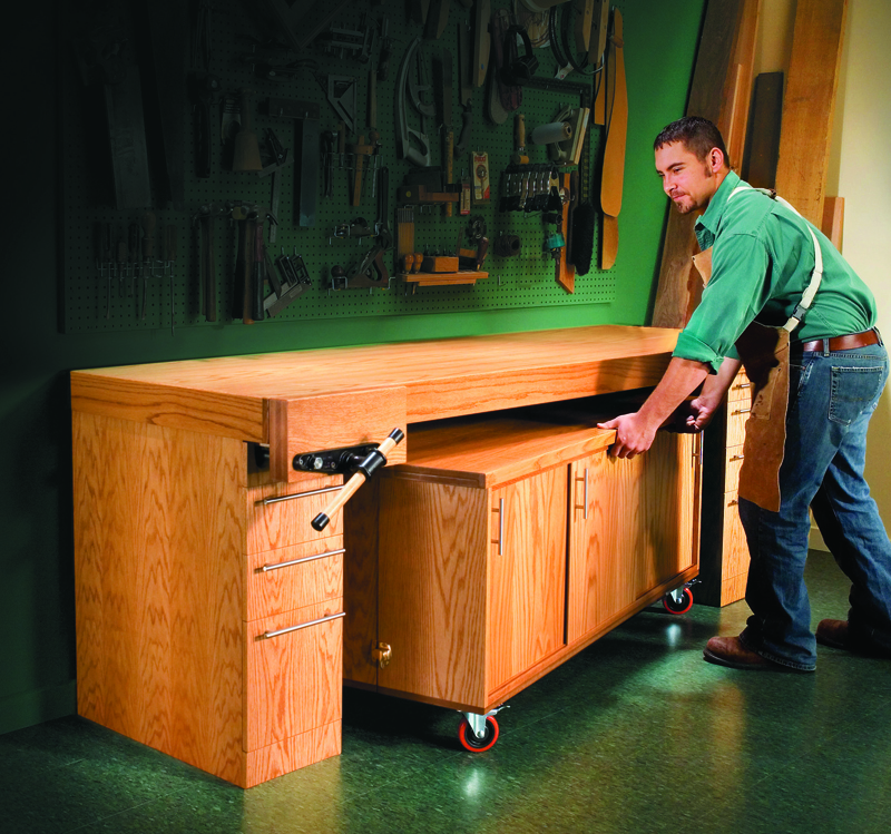
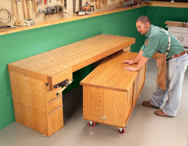
In our shop, we used to pile tools, parts and hardware on top of a wobbly workbench made from 2x4s. When we had to glue a project together, we shoved everything aside. Finally, we got tired of searching for tools and space and set out to make a new style of workbench. Our new workstation is two benches in one. The best part is a rolling storage unit that opens into a huge assembly table. Closed, it tucks right under the bench. We built the bench’s top as a torsion box, so it can span the distance over the assembly table without sagging. Both parts are made from home-center materials using simple joinery. Two work surfaces, lots of drawers and shelves—what a great excuse to buy more tools. |
Click on any image to see a larger version.
|
THE WORKBENCH
Build the Torsion Box1. Cut out the parts according to the Workbench 2. In the skins, drill the screw holes that will be 3. Lay the bottom skin on a pair of plywood 4. Cut the inner torsion-frame parts (D, E) to size 5. Screw the short inner torsion-frame parts (E) 6. Test-fit this grid assembly in the outer frame that’s 7. Flip the assembly and add screws through the 8. Now flip the torsion-box assembly back and glue 9. Next, add the top skin with glue and screws. 10. Drill the access holes through the torsion box 11. Cut the side trim boards (G, H) to final size. 12. Screw the work top into place (Photo 6). For a nice 13. Now is good time to glue together the three parts Build the Base Cabinets14. Cut out the sides, top and bottom, and back (M, 15. Cut slots for biscuits in the cabinet parts (Fig. A). 16. Because these cabinets are only 10-1/2 in. inside 17. Assemble the cabinets with biscuits, glue the cabinets Assemble, Install the Drawers
|
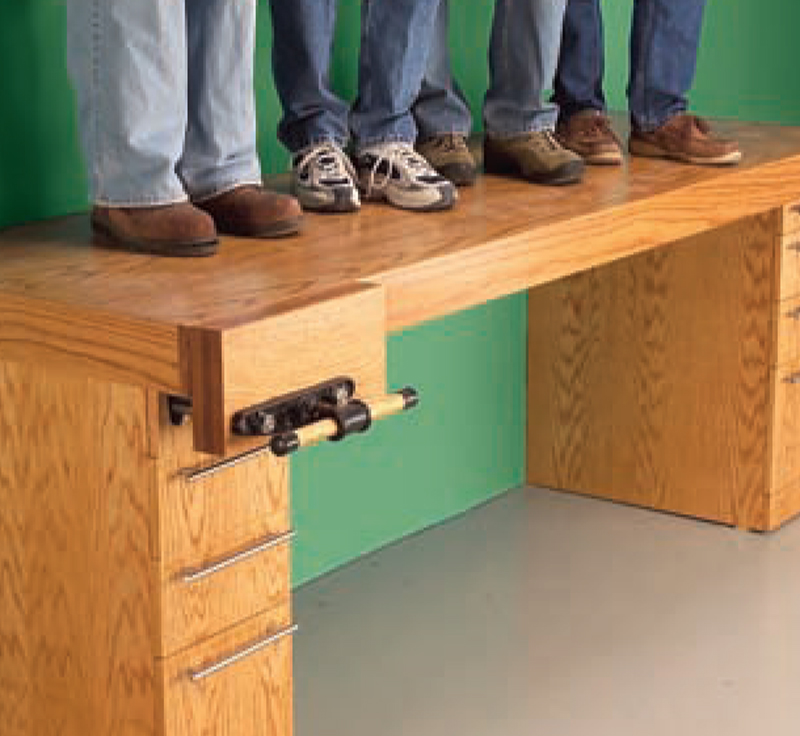
Rigid Top. This bench’s top is amazingly
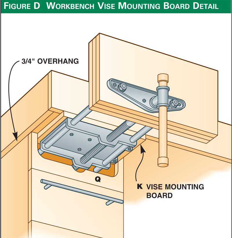
Sturdy Vise. The front vise has a large
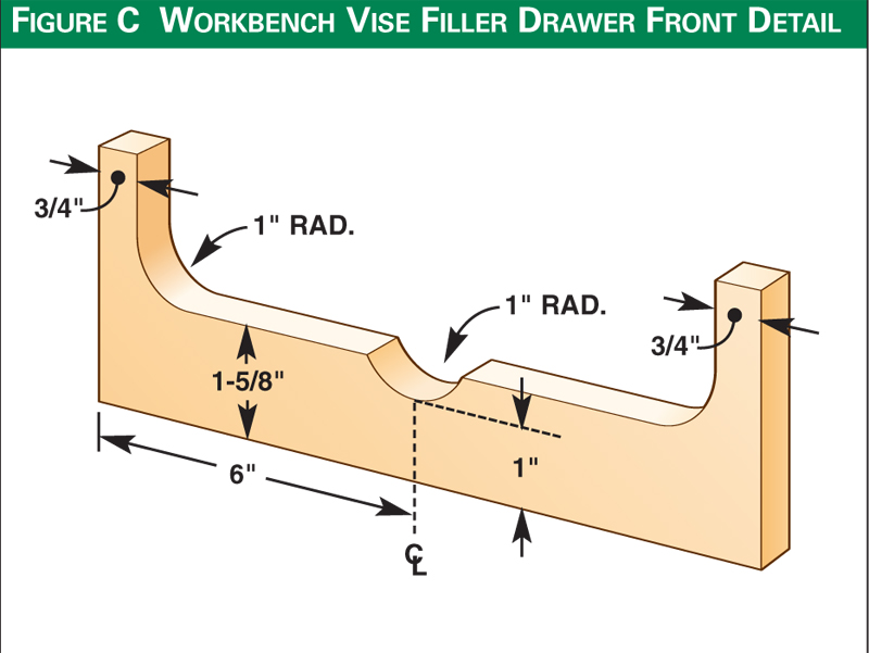
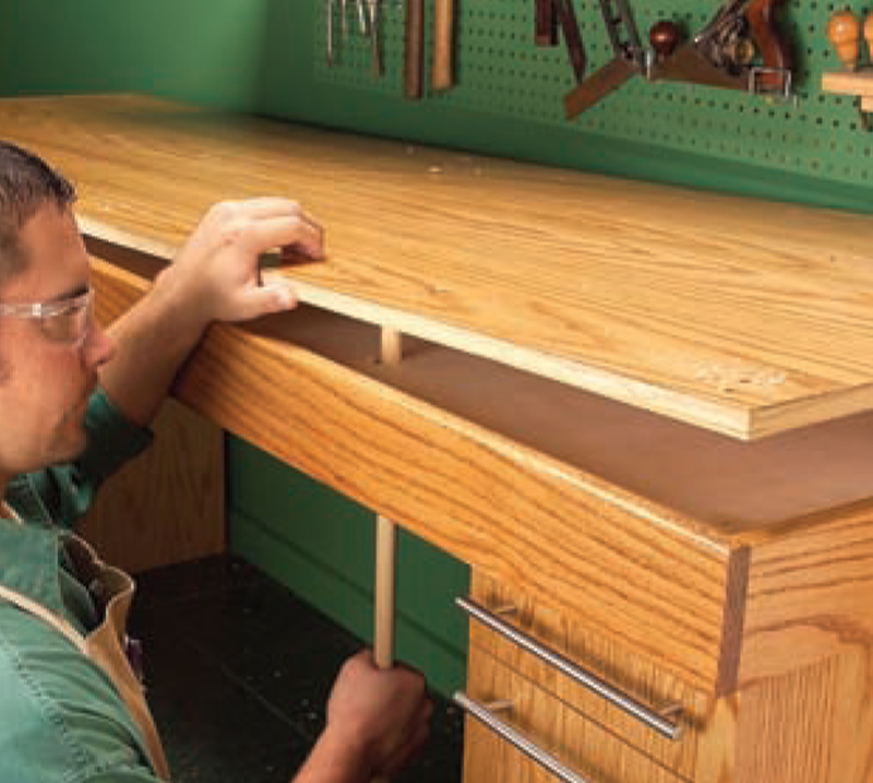
Replaceable Top. The bench’s top is
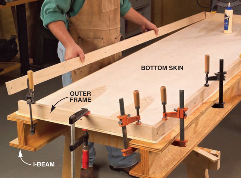
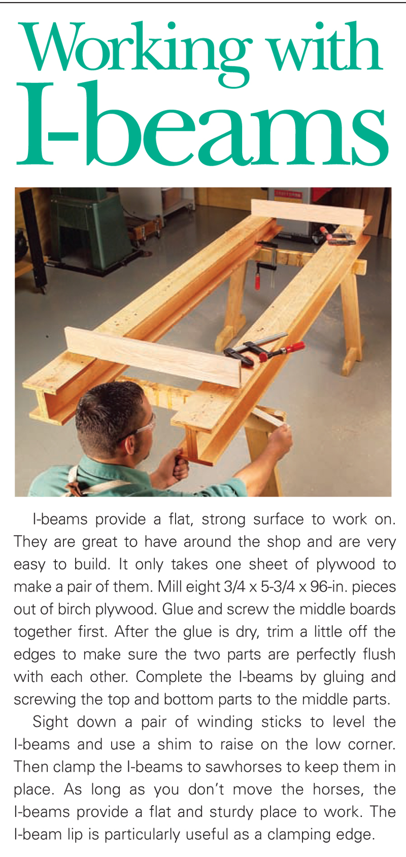
1. A torsion box is composed of two sheets of plywood, or Working with I-Beams
2. Cut the bridle joints on the inner torsion-frame parts with a
3. Test-fit the inner torsion-frame assembly. It should slip into
4. Flip the assembly and screw the bottom skin to the
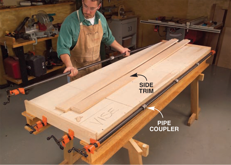
5. Glue the trim boards to the torsion box. Install them
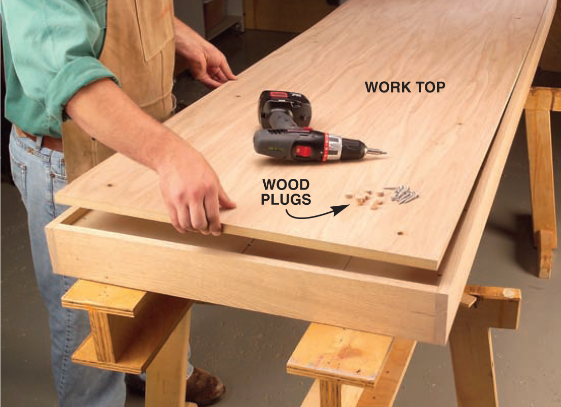
6. Install the work top. Screw it to the torsion box and use
7. Use spacers to position the drawer slides for mounting to
8. Add levelers to the base cabinets if your shop floor is |


THE EXPANDABLE ASSEMBLY TABLE
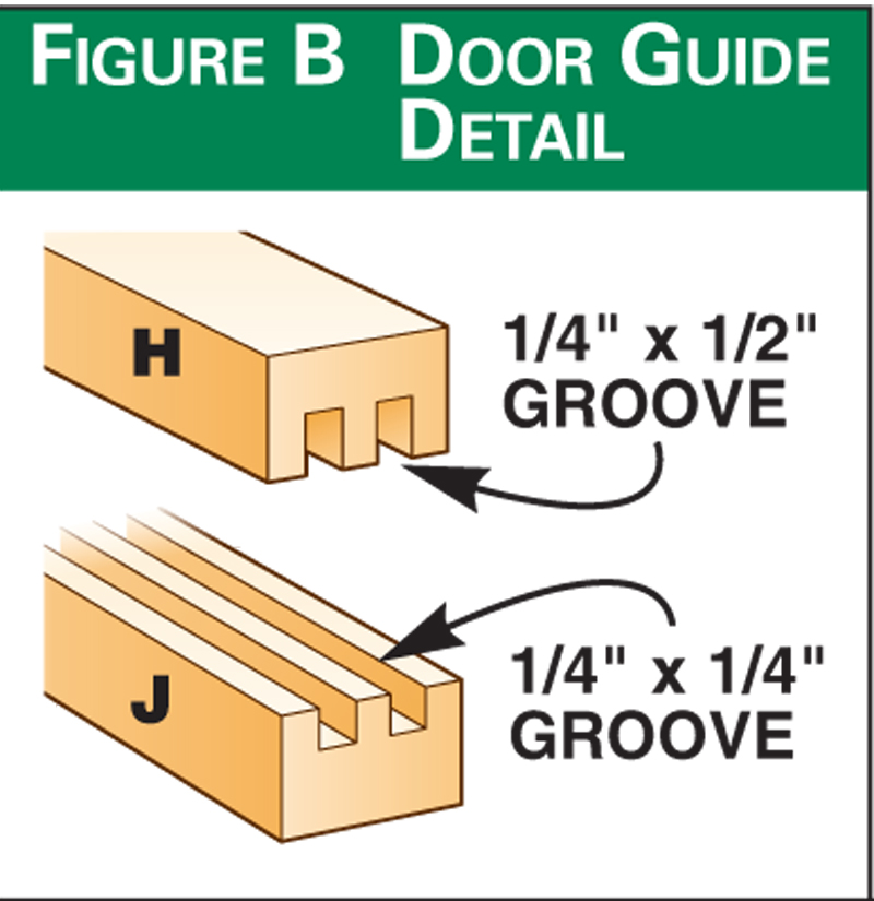
Build the Base Cabinets1. Cut out the parts for the base cabinets according to the 2. The cabinet subtops and subbottoms, ends, partitions, 3. Apply iron-on edge banding to the front edges of the 4. Assemble the partitions, subtop, subbottom and back 5. Attach the bottom (F) and top (G) with screws and glue. 6. Add the top and bottom door guides (H, J, Fig. B; Photo 2). Add the Hinged Panels7. Make three sets of hinged panels by attaching the 8. Add hinges to the outer edges of the panels. They go on 9. Mark the locations for the hinged panels on the back of the cabinets (Fig. A). Center the middle panel and then 10. Attach the pairs of panels to one cabinet first 11. Next, attach the panels to the back of the other cabinet 12. With the hinged panels installed, fold the cabinets 13. With the cabinets locked together, roll them over Add the Removable Top14. Roll the cabinets back upright and unfold them. 15. Carefully measure the opening width for the removable 16. Glue the edge strips (L) to the removable top panel. 17. After the glue has dried, test the fit. It should fit 18. Check the fit of the removable top with the cabinets 19. When the removable top fits correctly, round the 20. Drill holes for shelf supports and add the adjustable 21. Finally, add the sliding doors (N, P, Photo 7) and 22. We finished our cabinet with a golden oak stain and
Assembly Table Cutting List
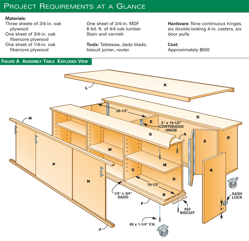
Fig. A: Exploded View
Fig. B: Door Guide
Fig. C: Plywood Cutting Diagrams
This story appears in American Woodworker January 2006, Issue #119.
|
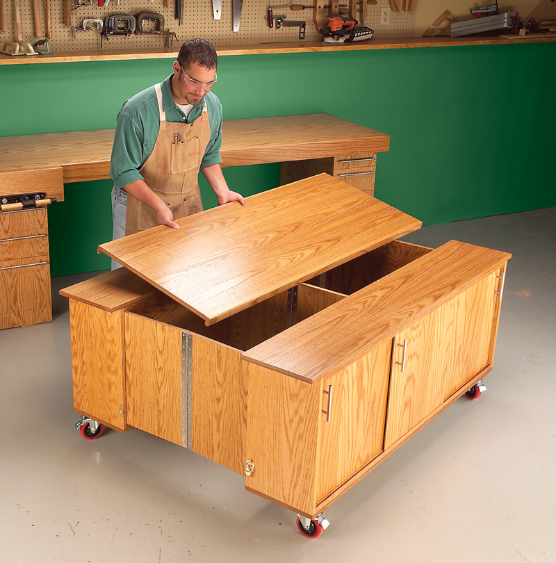
Expandable! This assembly table opens
Lots of Storage. The base cabinets
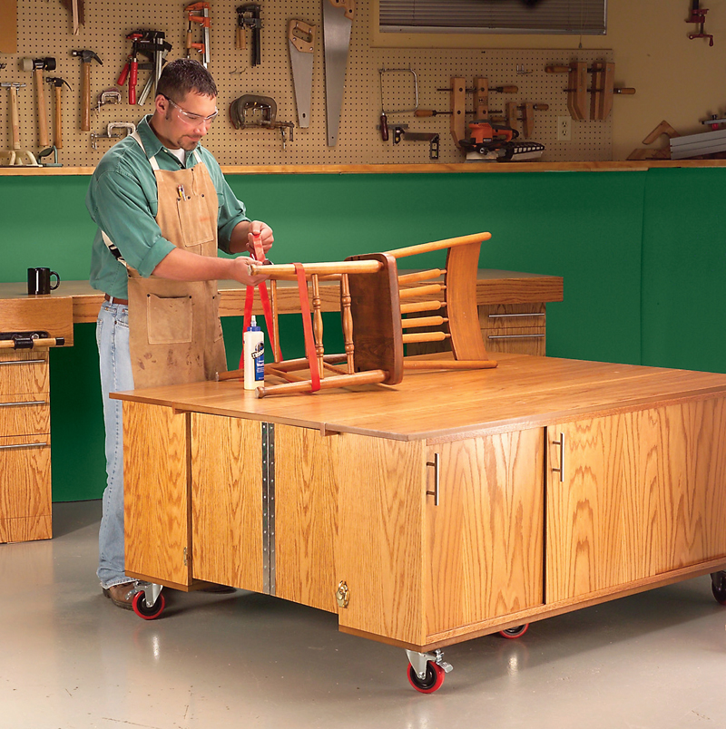
Perfect Height. The large work surface
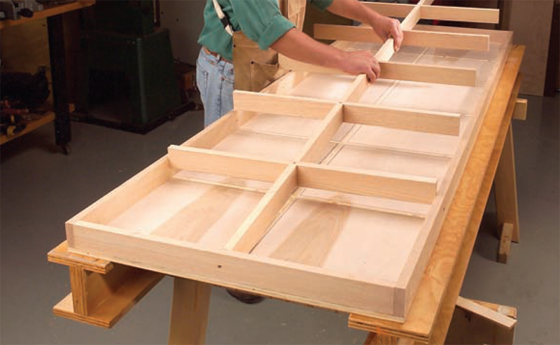
1. The assembly table is composed of two identical cabinets. Joinery
2. Glue and clamp the door guides to the doubled-up top
3. Install the hinged panels to the back of one cabinet,
4. Attach the hinged panels to the back of the second cabinet.
5. Install the wheels. The center wheels provide support for
6. Measure for the removable top. You want the top to fit
7. Slip the sliding doors into the slotted guides. The doors |


Here are some supplies and tools we find essential in our everyday work around the shop. We may receive a commission from sales referred by our links; however, we have carefully selected these products for their usefulness and quality.


