


We may receive a commission when you use our affiliate links. However, this does not impact our recommendations.

Country-Style Grandfather Clock
By Tim Johnson
For many of us, a grandfather clock is the ultimate project. Traditional high-style clocks often involve such advanced skills as spiral turning, veneering and figure carving, to say nothing of the cost of the figured wood.
This country-style tall clock is much, much easier to build, while still being a grand, stately and impressive piece of furniture. The only tricky part is the top,with those curved moldings, but we’ve come up with some jigs and a building process that makes it almost goof-proof.
In essence, this clock is composed of three boxes that are connected with cove moldings. The ornate “hood” rests on top of the slender “waist,” which is supported by the wide, footed base.The base and waist boxes are fairly easy to build, so we won’t spend much time explaining their construction.We’ll concentrate on the hood. Its arched top,door and moldings are the challenging part of this project. A prototype, a shopmade compass and a couple of shopmade jigs are the keys to success.
Behind the beautiful paper dial, this clock is designed to house either a traditional mechanical or modern quartz movement (see Sources, below). You’ll need about 55 bd. ft. of lumber; we used cherry. Including the mechanical movement and paper dial, we spent about $800 to make our clock. Choosing a quartz movement will knock off about $250. A hand-painted dial is an authentic, but costly upgrade (see Sources, below).
This project takes a well-equipped shop.You’ll need a tablesaw with an accurate miter gauge, a bandsaw, a router table and router, a drill press, a spindle sander (or sanding drum for your drill press), a jointer, a planer and a good selection of router bits (see Sources, page below).
The Base and Waist
Assemble the face frames of the base and waist sections (B1-B3 and W1- W3, Fig. A) with splines (Photo 1). The slots for the base’s face frame run full length on all the inside edges, to house the panel (B4).The waist’s face frame doesn’t house a panel. Here, the slots stop, so the splines don’t show.You have to round one end of the splines to fit these slots.
When you rout the slots,orient the face sides of the pieces the same way, so the joint surfaces will be flush.
Cut the cross-grain splines on a tablesaw equipped with a zero-clearance insert.The spline should slide into the slot easily,with just enough tolerance to keep it from binding.
Apply glue to both slots, slip the spline into the rail and assemble the joint.Don’t put any glue on the spline.Clamp the face frames together, and check to make sure they’re square. Using the patterns (Detail 1, below), saw out the feet on the base frame and sides.
Dadoes and Rabbets
The base and waist assemblies go together with dadoes and rabbets (Photo 2). Cut notches in the waist sides (W4) for the backs (B8 and W11).
To keep the waist assembly square during glue-up, install a piece of scrap plywood as a substitute for the back.
It’s important for the waist sides to extend exactly 4-5/8- in. above the top of the face-frame rail so the clock movement installs at the right height (Fig. B and Photo 6). If you use a different movement, you may have to adjust the dimensions.
Install the back (B8) and glue the three centering blocks (B7) on the base. They center the waist section and act as anchors for the screws that fasten the two assemblies together (Fig.A). Lower the waist assembly into position (Photo 3), drill pilot holes and screw the two sections together.
Tablesawn Cove Moldings
Make both cove moldings (W6 and W7, and Detail 2, below) from the same tablesaw setup (Photo 4). Use your miter gauge, set at 45 degrees, to position the fence. To create the cove, start with the blade only 1/16-in. above the table.Push the workpiece over the blade,while holding it firmly against the fence.Make successive passes, raising the blade about 1/16 in. each time,until it reaches its maximum height (1/2 in.). You’ll have to sand the coves smooth after sawing.
Cut the back shoulders with the blade tilted away from the fence (Photo 5). The moldings are different sizes, so they require different fence settings. Make sure the back shoulders are square to one another.Complete the moldings by sawing the square front edges.
Make the half-round bead (W8) with a bullnose bit (see Sources, below). Rout both edges of a wide board and then saw off the thin moldings. Glue the beads onto the coves.
Miter the front molding pieces and glue them in place. Fit the miters on each side piece before cutting them to length. Glue the miter joint and the first 2 or 3 in.of the side molding. At the back, fasten each side piece with a screw from inside the case, to allow seasonal movement.
The upper cove moldings have to be installed precisely (Photo 6), so the dial, (which mounts with the clock movement on top of the waist) lines up with the door opening in the hood.
Lipped Door
The waist’s door (W9) has rounded-over front edges and a 3/8-in. rabbet around the back. Install the door with off-theshelf hardware (see Sources, below).
The Hood
The hood features the same construction as the base and waist sections: stopped slots, rounded splines,dadoes, rabbets and miters (Fig.C). The arches are the new challenge.
The hood’s arched components are all derived from the shape of the metal dial plate (Fig.D). The opening in the dial frame (H4-H6) masks the outer edge of the dial. The fill block (H9) fills the cavity between the dial frame and the front cornice board (H10). These two parts define the upper arch of the door. The door (D1-D4) sits directly in front of the dial frame and its opening for the dial is the same size. The cornice boards (H10 and H11) are the bottom pieces of the built-up cornice moldings, which also include coves (H12 and H14) and ogees (H13 and H15).
Make a Prototype
The arched pieces require careful layout and execution.The relationship between these pieces can be downright confusing.Our best advice is to build a prototype of the hood so you can test your procedures, become familiar with the parts, and verify your results.A half sheet of MDF ($20/full sheet) is more than enough. If you make mistakes in MDF, who cares?
When you manufacture the hood’s arched pieces, follow these guidelines:
• Always use centerlines for alignment.Mark them on all sides of every blank. When you sand or cut off a centerline, re-mark it.
• Make a dedicated compass so your arches are always consistent (Photo 7).
• Be aware of the location of the arch’s centerpoint. Sometimes it’s on the blank, sometimes it’s below (noted on Cutting List, below).
• Be precise: Carefully sand each arch to the line (Photo 8).
Assemble the Hood Box
Build the hood’s base frame (H1 and H2) and test its fit on the assembled waist. It should lay flat atop the upper moldings, kiss the waist sides and butt up to their fronts.
Cut rabbets in the sides (H3) for the door and dial frame. Then cut additional rabbets for the top (H7) and the back (W11). Finally, bandsaw notches for the fill block (H9).
Assemble and glue the dial frame (H4-H6) after marking, cutting and smoothing the inner arch on its upper rail. You’ll need a thinner slot cutter for this frame, because of its 1/2-in. thickness (see Sources, below). Glue the hood together; the dial frame arch should sit dead-center. Next, center the hood on the base frame and screw them together. After sawing and sanding the arches, glue the dial frame crown (H8) and the fill block in place (Photo 9).
Make the Arched Molding
The cornice moldings are built up in three pieces (Fig.C and Detail 3, below). You’ll need to make arched and straight versions of each built-up molding.
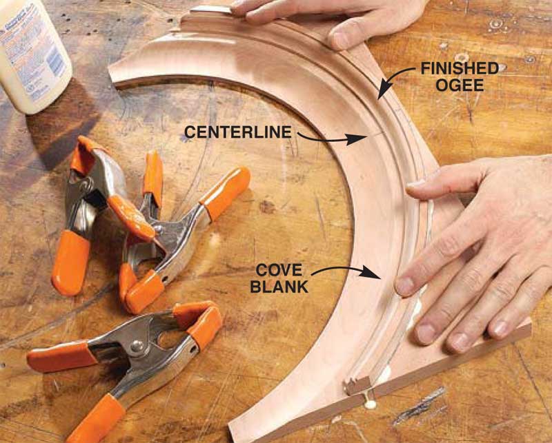
Keep things simple by making the blanks for the arched front cornice board (H10), cove and ogee moldings (H12 and H13) the same size. This allows you to use the same layout tools and procedures throughout. Lay everything out on the front cornice board blank (Photo 10).
Draw both the inside and outside arches on the cove and ogee molding blanks, but cut and smooth only the inner arches. Check the curves of these arches on your pattern before you rout the profiles (Photo 11). Next, cut and sand the ogee molding’s outer curve and glue it to the coved blank (Photo 12).
Mark and cut the 28-degree angle miters on the built-up arched molding (Photos 13 and 14). Miter the straight shoulder moldings at the same angle.
Glue the straight shoulders to the arched molding, using a jig made by fastening a fence to a piece of MDF (Photo 15). Simply fasten the arched molding to the MDF while holding its mitered points against the fence. Apply glue and clamp the straight shoulders in place.
Install the Cornice Molding
Cut and sand the arch on the front cornice board (H10) so it matches the arch on the fill block. Rout the ogee profile on its bottom edge, taking care to leave a 3/8-in.-wide flat surface for the door’s hinge pivot screw.Center the cornice board blank on the fill block,mark the corners and cut the miters. Glue on the front cornice board, then fit and fasten the sides (H11).
Measure the exact length of the installed front cornice so you can miter the built-up cornice molding. For the angled blade to cut all the way through the built-up moldings, your mitering sled can’t be more than 1/2-in. thick (Photo 16).
With the hood on its back, glue the cornice molding in place, using the layout marks and centerline on the cornice front.Then install the side moldings (Photo 17).
Slide the hood into position on the case so you can locate and install the retainer blocks (W10). Then fit and install the waist back (W11). The adjacent edges of the waist and base back pieces are rabbeted, to keep out dust. Sand and finish the case.
Build the Door
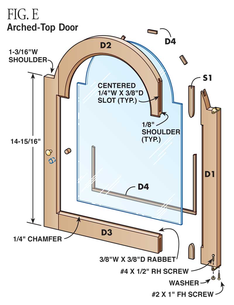
Clamp the door’s stile and rail blanks (D1-D3) together without glue, to form an oversized rectangular blank.Mark the door’s shoulders and then draw both of the arches on the top rail.The outer arch runs onto the stiles before it meets the shoulder line.
After disassembling the blank,cut and sand the upper rail’s inner arch. Then glue the door blank together and cut the shoulders and the outer arch (Photo 18).
Rout the chamfer around the door’s inside edge and square the corners with a chisel. Then rout a rabbet for the glass around the back inside edge (square these corners, too). Have the arched glass cut at a commercial glass company or stained glass studio (about $20).
Trim the door to fit the opening in the hood (Photo 19). Leave 1/16-in. clearance (a dime’s worth) on the sides, around the arch and at the shoulders. To keep the door’s opening aligned with the opening in the dial frame, cut 3/32-in.off the bottom for the hinge and washer after you’ve fit all the other sides. The washer provides clearance so the hinge doesn’t wear on the base frame.
Install the Mechanism
The metal dial plate and the clock movement are connected by a universal adapter called the “false plate”(see Sources, below). Epoxy the dial plate and false plate together after cleaning both surfaces.They have to be perfectly aligned, or the dial will be crooked when it’s attached to the mechanism. Drill out the holes for the movement’s winding posts and sand the burrs flat.
Adhere the adhesive-backed paper dial (it comes with mounting instructions, see Sources, below) to the dial plate. Then attach the dial plate to the movement (Photo 20).
With the seatboard/ movement/dial assembly resting in place on top of the waist sides, carefully slide the hood into position. The dial frame should butt up against the dial.You’ll likely have to adjust the seatboard to center the dial in the opening before you fasten it to the waist sides.
Lock the hood in place (Photo 21). Install the hands, weights and pendulum. Now, what time is it? Step back, it’s time to enjoy what you’ve accomplished!
The Quartz Movement

Cutting List

Detail 1: Pattern for Base Cutouts (1" Grid)

Detail 2: Pattern for Cove Molding

Detail 3: Arched Cornice Molding Profiles

Fig. A: Base and Waist Sections
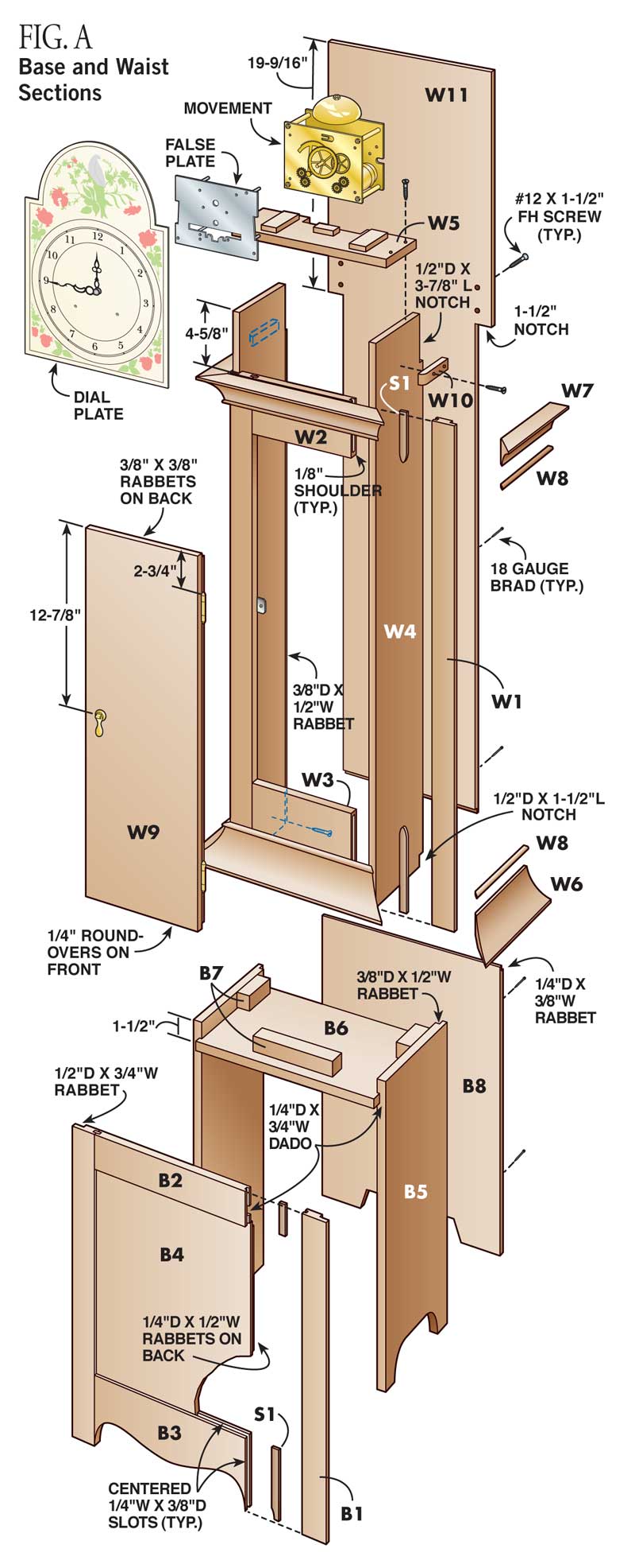
Fig. B: Hood Cross Section
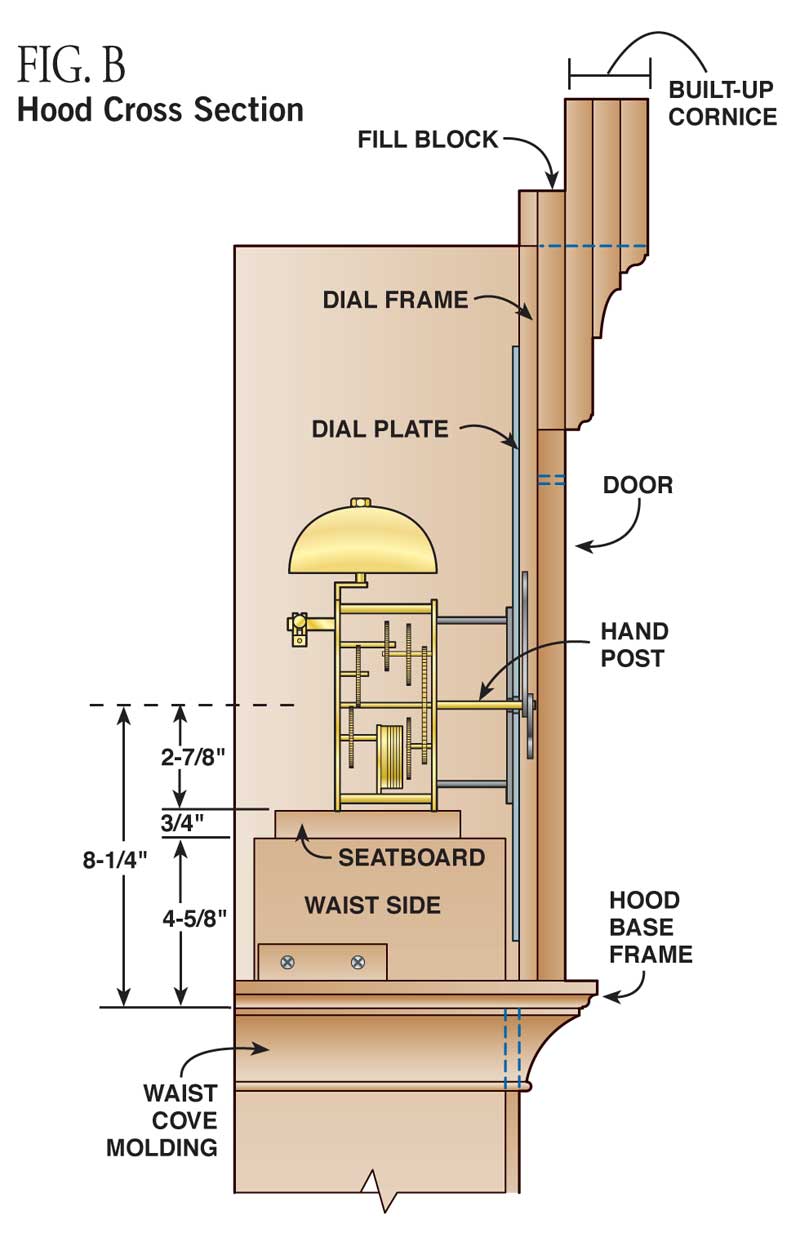
Fig. C: The Hood

Fig. D: The Arches
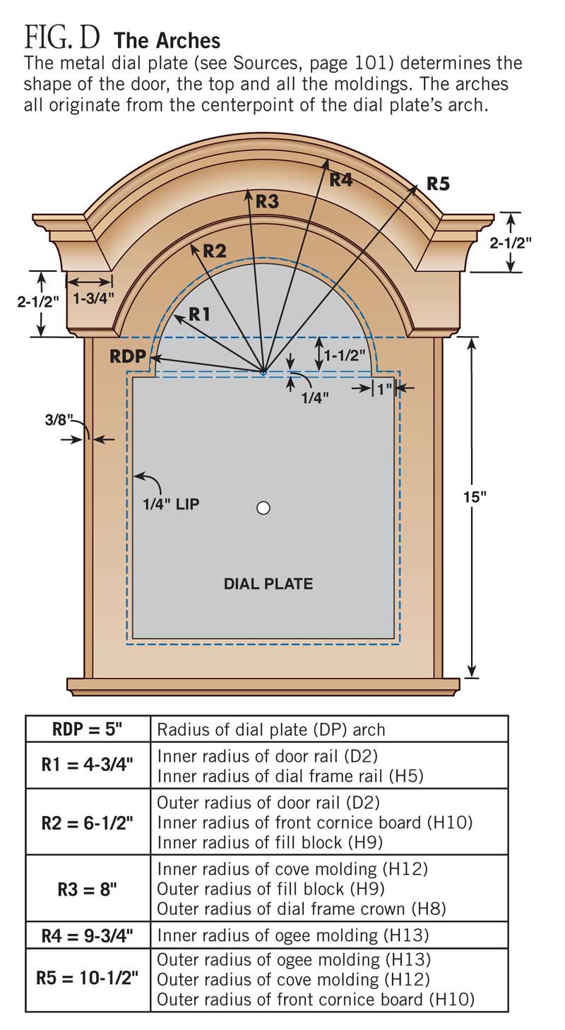
Fig. E: Arched-Top Door
Click any image to view a larger version.
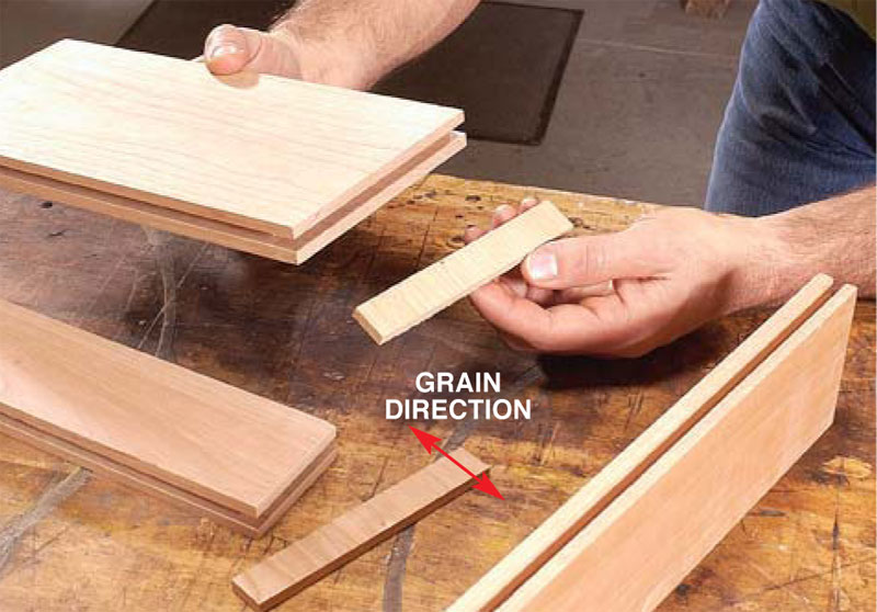

1. Slots and splines join all of the face frames. Cut the slots on your router table and the splines on your tablesaw.An oversized bearing limits the depth of the slots. For strength, the spline’s grain must run across its width.

2. Rout rabbets for the sides on the edges of the face frames.Then, when you glue up the base and waist sections, the edges of the face frames virtually disappear, because they’re so thin.

3. Place the waist on the base.Then fasten them together with screws into the centering blocks.

4. Cut the cove moldings using this setup. First, unplug your saw. Raise the blade 1/2-in. above the table.Then mark the throat insert where the back tooth emerges. Clamp a fence 9/16-in. behind this mark, angled at 45 degrees.

5. Rip the back sides of the cove molding at 45 degrees. To support the molding for the second 45- degree cut, reattach the offcut from the first cut with double-faced tape.

6. Attach the upper moldings flush with the top of the front rail.The hood rests on top of this molding, so use clamped-on guides to make sure the moldings are level sideto- side and front-to-back.

7. Draw arcs for all the arched pieces with a shop-made compass. Centerlines drawn on each blank keep the arcs centered.When the arc’s centerpoint lies below the blank, as shown here, house it on a separate extra-long piece. Mark the centerline of this piece as well.
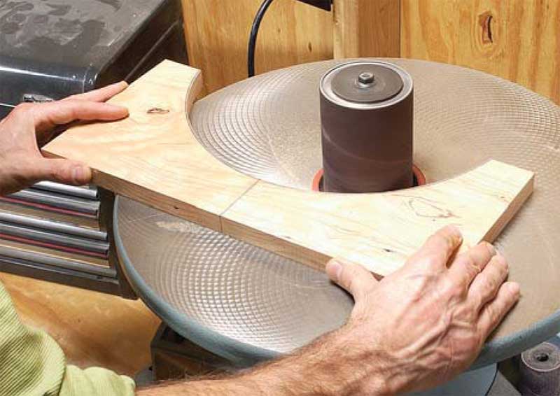
8. Sand the arches true after rough-cutting them on the bandsaw. If you don’t have a spindle sander, use a sanding drum on your drill press.
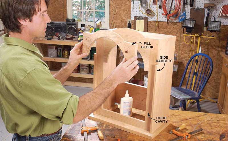
9. Installing the fill block completes the recess for the door and readies the hood for its arched cornice.
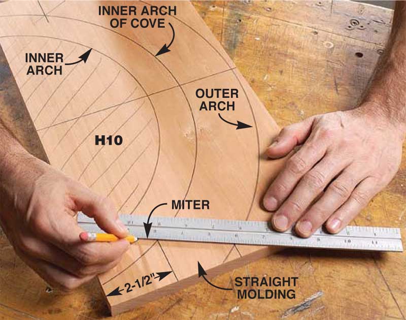
10. Make a pattern for the moldings right on the blank for the bottom-most of the three boards that’ll make up the cornice. First, lay out the arches.Then establish the miters.

11. Rout the arched moldings before you cut the outer curves, so the blanks are big enough to handle safely.A start pin on your router table will give you additional control.
12. Build the cornice molding by gluing one routed piece on top of another. Leave a straight edge on the bottom piece to help you cut the miters later.

13. Mark the miters on the molding, using the layout lines from the pattern you created earlier (Photo 10).

14. Miter the built-up arched molding using your miter gauge, the remaining straight edge of the blank, and the reference lines you’ve just drawn.

15. Glue on the straight shoulders, using a jig to keep everything in place.Waxed paper keeps the molding from sticking to the jig.

16. Miter the assembled molding, using a sled with mitered edges. Cut the sled so it’s exactly the length that the molding should be cut to. Center the molding on the sled and screw it in position, making sure it lies flat. Line up the sled’s mitered edge with the saw blade and make the cuts.

17. Fit the miters and fasten the side moldings. Use a couple of pin nails to hold the moldings in place while you apply the clamps.
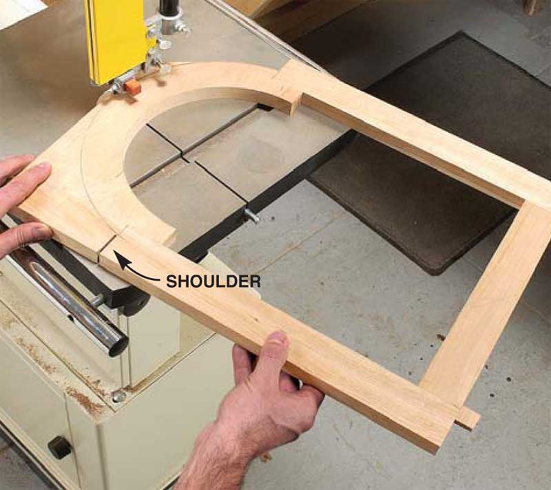
18. Cut the door’s outer arch after gluing the door together. Before cutting the arch, cut the door’s straight shoulders.
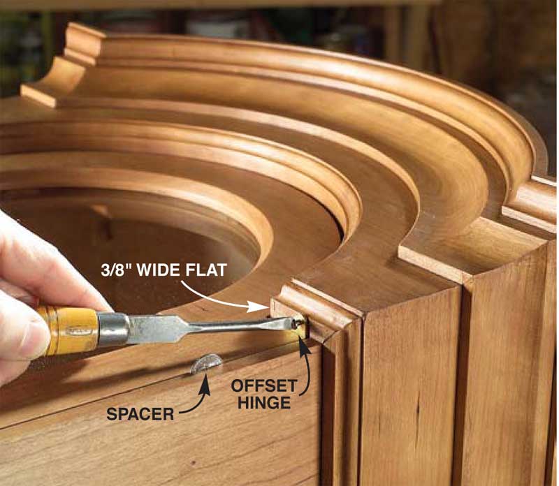
19. Install the door. Special offset hinges (see Sources, below) allow the door to open without binding. The mounting screw acts as the pivot pin.

20. Fasten the dial to the clock movement after fastening the movement to the seatboard (W5). Latches on the movement lock the posts on the false plate.

21. Slide the hood into position on top of the waist molding. Retaining blocks on the waist sides hold it in position. Fasten the hood to the back with brass hooks.
Sources
Note: Product availability and prices are subject to change.
Merritt’s Clock Repair Supplies, merritts.com, 800-345-4101, P-1322, metal dial plate; P-1344, false plate; P-1126C, complete 8-day movement (includes pendulum, weights, hands, etc); P-176, brass pivot hinges (pr); P-92A, brass hooks (6-pak); P-1375, quartz chime movement.
TEC Specialties, tecspecialties.com, 570-323-0594 (9-5 eastern, M-F), 121695, 12" paper dial (face) for grandfather clock.
Dial House II, 770-943-5676, Hand-painted grandfather clock dials.
Jesada Tools, jesada.com, 800-531-5559, Router bits (all 1/2" shank): 622-364, 1/4" slot cutter; 622-348, 3/16" slot cutter; 624-127, slot cutter arbor; 791-014, oversize bearing for 3/8" depth cut; 611-690, 3/4" x 1" straight; 654-503, 3/8" bull nose; 638-754, 1/4" round-over; 637-722, 1/4" cove; 636-920, 45-degree chamfer; 600-640, rabbeting bit and bearing set; 690-504, cove raised panel; 640-850, 3/4" Roman ogee; 640-770, 1/2" Roman ogee.
Rockler, rockler.com, 800-279-4441, 29272, round magnetic catches (4-pak); 65836, 3/8" inset magnetic catch; 27003, 3/8" overlay hinges (pr); 35659, Pendant pull; 67553, 1/2" sash knob.
This story originally appeared in American Woodworker May 2003, issue #100.

Here are some supplies and tools we find essential in our everyday work around the shop. We may receive a commission from sales referred by our links; however, we have carefully selected these products for their usefulness and quality.


