We may receive a commission when you use our affiliate links. However, this does not impact our recommendations.
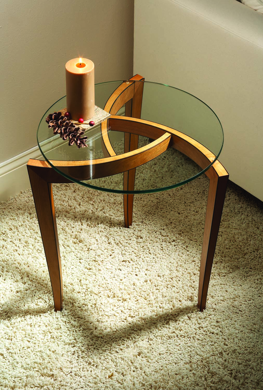
Tripartite occasion. This three-legged occasional table can be made with steam-bent hardwood or from bent laminations. This example is of steam-bent cherry with ebony inlay.
Steam-bending or bent laminations can be used to make this eye-catching design.
The design of this table is part of a series that I revisit from time to time. The original concept for the series was based on a pinwheel (a common example of which is a child’s pinwheel on a stick that blows in the wind.) This shape lends itself to repeating one design element several times then attaching them together, an efficient approach when making furniture. So far I’ve made several different stools, cabinets and even massive boardroom tables based on the same pinwheel motif. Generally speaking, I come up with an idea then problem-solve how to do it, often relying on the well-documented history of furniture making in books and magazines.
For this table I revisited a sketchbook that is 25 years old. At the time I had completed a commission for stacking tables with Australian lacewood tops and steam-bent cherry frames. In my design exploration there were several sketches that I thought had some value but didn’t work for that particular commission so so I filed them away for use at a later date. My old sketchbooks have become an idea bank that I’ll make a withdrawal from when I’m casting about for something to make.
To start this table I did a few more sketches then drew a full-size plan view that gave me the radius for the curve. From this I made a rough full-size mock-up of the table, the curves were simply band sawn from spruce 2x4s then glued and air nailed together. After holding up a leg at various angles, I expeditiously hand cut the miter joint where the curves met the legs.
With the basic idea confirmed, I made a bending form that would accommodate both laminating and steam-bending techniques. This way, I could use either exotic or domestic species. Here I’ve made the table in air-dried cherry that has been steam-bent. If the table were to be made in an exotic wood or if only kiln-dried domestic wood were available, then laminating would be the appropriate choice. However, my preference is to steam-bend solid wood when possible so I can avoid cutting or shaping through the glue lines in a lamination.
The Full-size Drawing
After my sketches, I always draw each project at full size. The drawings are often pretty basic, but it does get me thinking about the relationships of the various parts before cutting and possibly wasting wood. The drawing board is also basic. I put a piece of particleboard on sawhorses, lay out some cheap paper (bought on a roll) and use a drywall square to draw my lines. A beam compass or tension bows will draw the arcs. Any part I’m making can be laid right on the drawing to confirm the shape.
I’ve been woodworking for 35 years and have a full-size drawing rolled and stored alphabetically for every project. This step is very important in my design and construction sequence. Some projects are even built right over the top of the drawing. This drawing will help make the bending form, two cut-off jigs, the drill jig for the center joints and the center clamping cauls.
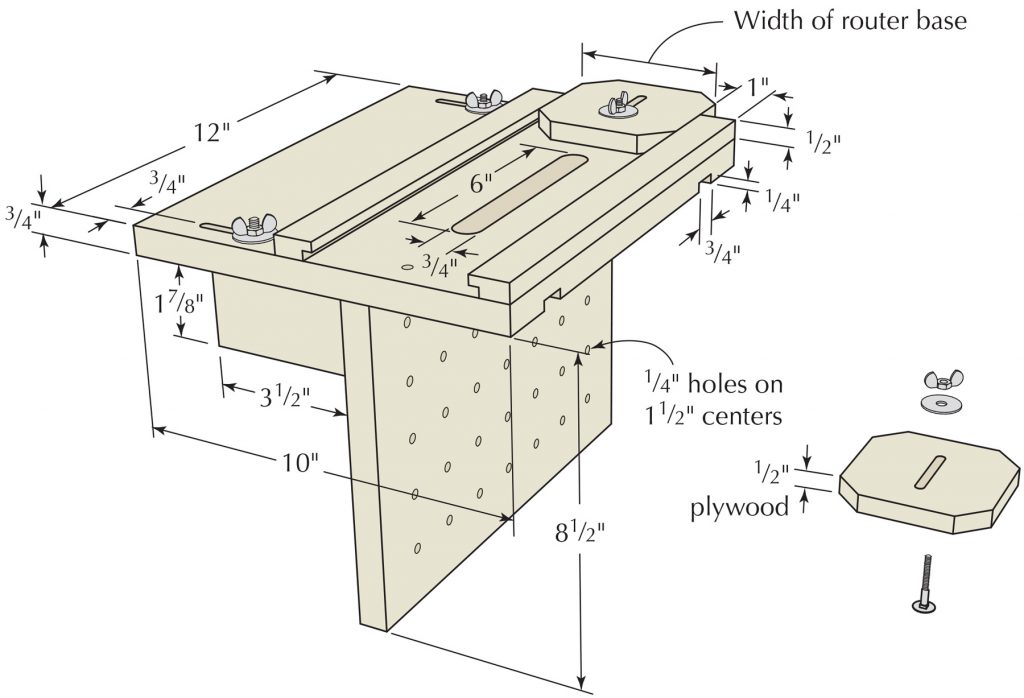
Making the Form
The drawing provided the dimensions of the particleboard form. The curved parts are 17⁄8“ wide (side view) so I laminated the three pieces of particleboard together for a total of 21⁄4“. The true radius for the arcs is 12″, so I made the form with a radius of 117⁄8“. The inside face of a lamination is smooth whereas the inside face of a steam-bent piece may not be. When I’m laminating I simply add a padding strip of 1⁄8“ hardboard to the form face. When steam-bending I can smooth out any imperfections along the inside and achieve the 12″ radius.
Draw out the radius on the form and cut it freehand on the band saw if you can follow the line closely, or use a circle-cutting jig on the band saw.
Steam-bending
I’ve used air-dried cherry for this table. In addition to steam-bending well, air-dried domestic wood is much more pleasant to work with hand tools and generates less fine dust when planing by machine. It can also be less expensive. I pay about $2.50 per board foot for 8/4 stock (but it will be more expensive if it is not available in your area). The bending blanks are 11⁄4“ x 2″ x 18″. If you are bending two at a time end to end, then the blank is 36″ long.
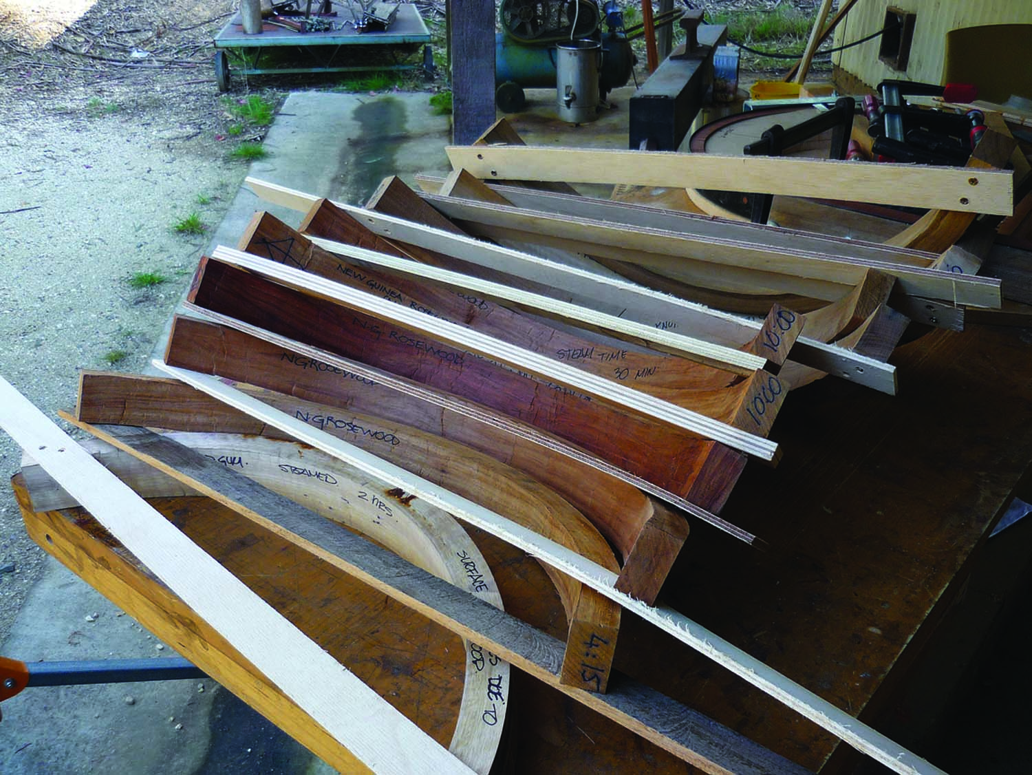
Two parts at one time. The parts are removed from the bending form after sitting for 10 minutes and are restrained with a wooden tie bar. They will acclimate to the curve in about seven days. Here are various air-dried woods that have been steam-bent.
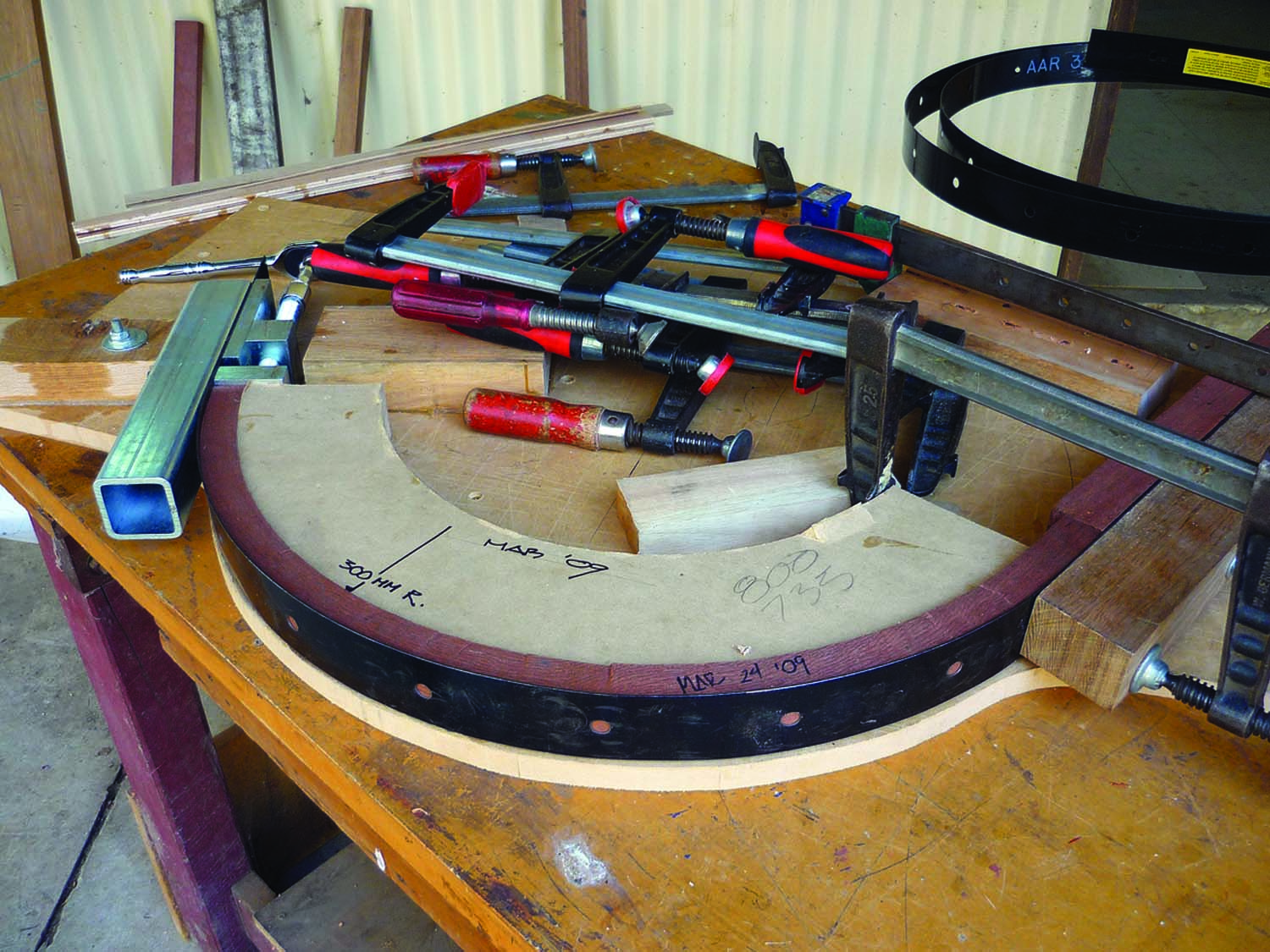
Compression strap. The end stops bolted to this Veritas compression strap stop the wood from stretching and failing. The inside face must be put into compression for successful steam bending.
The steam-bent curved parts on the table taper both in thickness, and in width along the 18″ length, but I usually bend parts that are machined parallel, then cut the tapers afterward.
I use a Veritas 2″-wide compression strap. In a nutshell, wood that has been steamed then bent around a form will always fail along the outside face. The wood fibers stretch then separate. However, if the piece of wood is restrained with a strap and end stops (and thus restrained from stretching), then the inside face is put into compression. Steamed wood will compress a phenomenal amount before it fails.
In this case, the double blank was 36″ long when steamed. After bending, the outside dimension remained the same while the inside was compressed to 321⁄2“. The adjustable Veritas end-stop assembly makes it easy to remove the compressed blank. The bent parts are transferred over to drying jigs and left to set for at least five days (seven is better).
When bent properly, the bent part has no memory of being anything other than its new shape.
Or Laminating
The three identical curves on the top can be laminated. I always use a fixed male form with a flexible female form. This approach makes clamping tapers much easier.
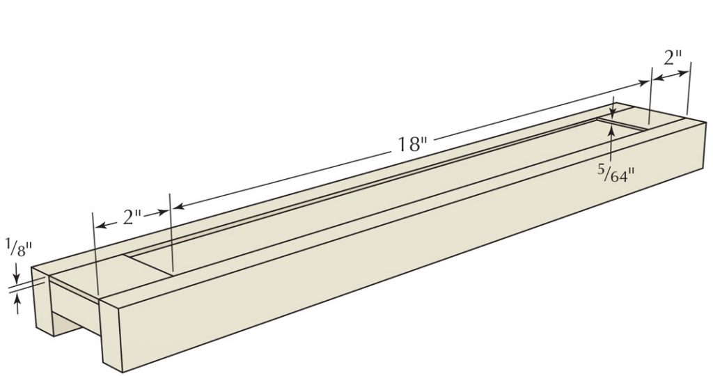
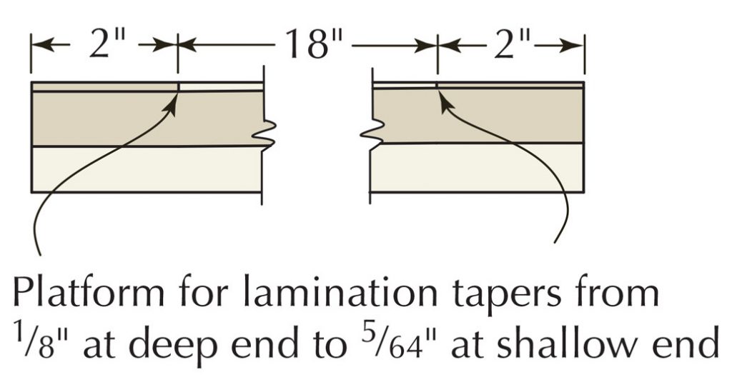
 For this application it is best to make tapered laminations so that when the outside curve is cut it doesn’t run obliquely through the glue and laminations. This would compromise the finish in the completed table. I use a jig on the band saw (see drawing above) to cut the tapered laminations. There are nine laminations on each bent part. The thick end is 1⁄8“, totalling 11⁄8“, while the thin end is 5⁄64“, totalling 45⁄64“, or just over 11⁄16“.
The block of wood that yields the laminations is marked with a triangle so it’s easy to reassemble the laminations the way they came off the board. Start with two boards 2″ x 4″ x 18″ long. They have to be machined to the same dimensions so they’ll fit in the jig. Rift-sawn grain is best because it disguises the glue lines and both the top and side surfaces have the same grain configuration.
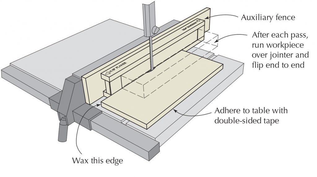
After each lamination has been band sawn, the boards are jointed and flipped end for end. This way the edges of the board remain parallel throughout the process of cutting the tapered laminations. You’ll get two stacks of laminations from each board, with the grain match missing by a lamination. If you forget to flip the board you’ll run out of wood on one end due to tapering.
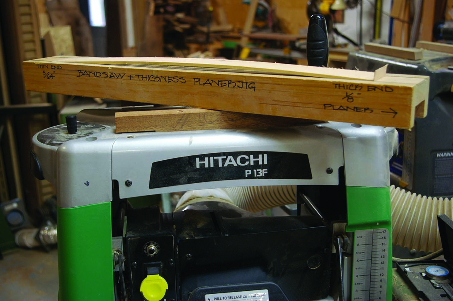
Band saw & planer jig. The shim makes the tapered lamination bow up about 1⁄8″. It is tack-glued to an end stop and flushed off with a knife. When the infeed rollers press the lamination flat it is wedged tight against the end stops. This avoids the laminations getting picked up and shredded by the planer.
After all the laminations are band sawn (all are band sawn on one face, jointed on the other face) the laminations can be passed through the planer on the same jig. A wonderful trick here is to tack-glue a slip of veneer to one end stop on the taper jig. The laminations will now fit only between the stops if they are bowed up slightly, about 1⁄8“. As they are passed though the planer (thick end first) the infeed and outfeed rollers press the bowed laminations down and snug between the stops. This will eliminate shredding laminations in the planer.
To spread out the clamping pressure I always add about 1″ of padding strips to the lamination. These are either extra laminations or strips of 1⁄8“ hardboard. This spreads out the clamping pressure and ensures even glue lines. I start clamping on the thick end and progress down the length, alternating the bars on either side.
For exotic woods I’ll use a slow-set epoxy; my choice here is System3, G2. For medium- or dark-colored domestic woods I’ll use Franklin Titebond III. On light woods I’ll use a high solids white PVA such as Franklin Titebond II. Adding at the very most 5 percent of cornstarch to the PVA will make it more rigid.
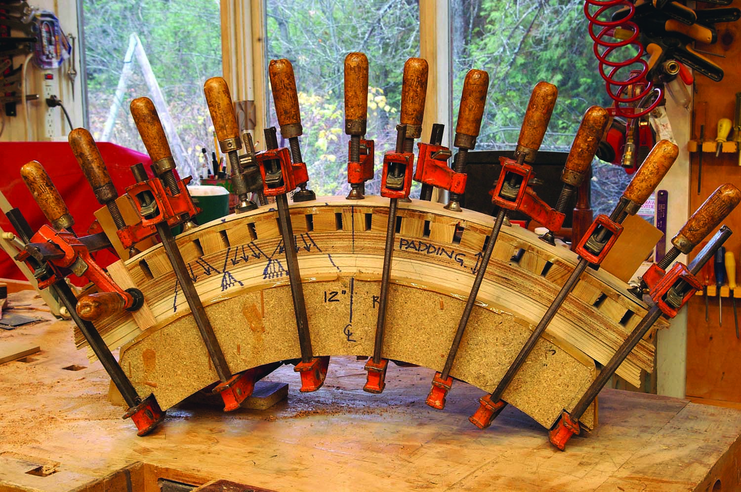
Particleboard lamination form. About 1″ of padding strips (hardboard) and a flexible caul (with the stapled cross blocks) spread out the clamping pressure so the glue lines are perfectly consistent. Start clamping at the thick end and alternate the clamps, working toward the ends.
I spread the glue with a notched metal spreader. This spreader deposits the perfect amount of glue – too much would make a wasteful mess; too little would yield dry joints. With domestic woods, glue has to be applied to only one side of each lamination. Exotic woods should have both sides coated.
Whether laminating or steam-bending, the three curved parts should be jointed then planed to 17⁄8” wide.
A Process in Design
I started with very rough sketches on tracing paper. I looked on the web for glass tops and found an 18″-diameter 3⁄8“-thick tempered glass top that was about the size I had in mind for this table. I thought the shape of the table should dominate the glass so I let the legs stick out farther than the diameter of the glass.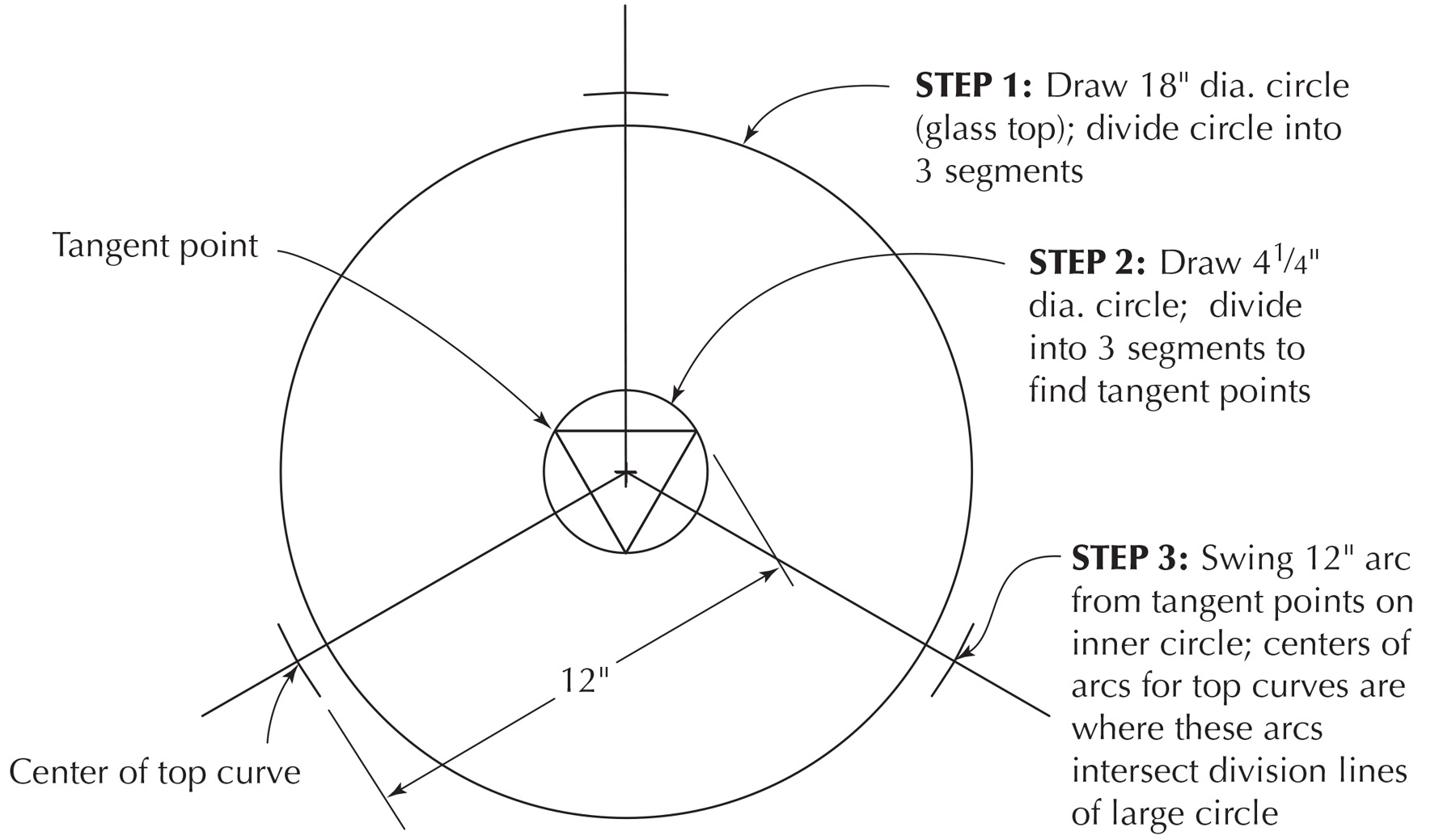
I made a full-size mock-up from the rough sketches to prove the concept in three dimensions, then used information from the sketches and the mock-up to generate an accurate full size drawing. The full-size drawing provides all the information needed to build the table precisely.
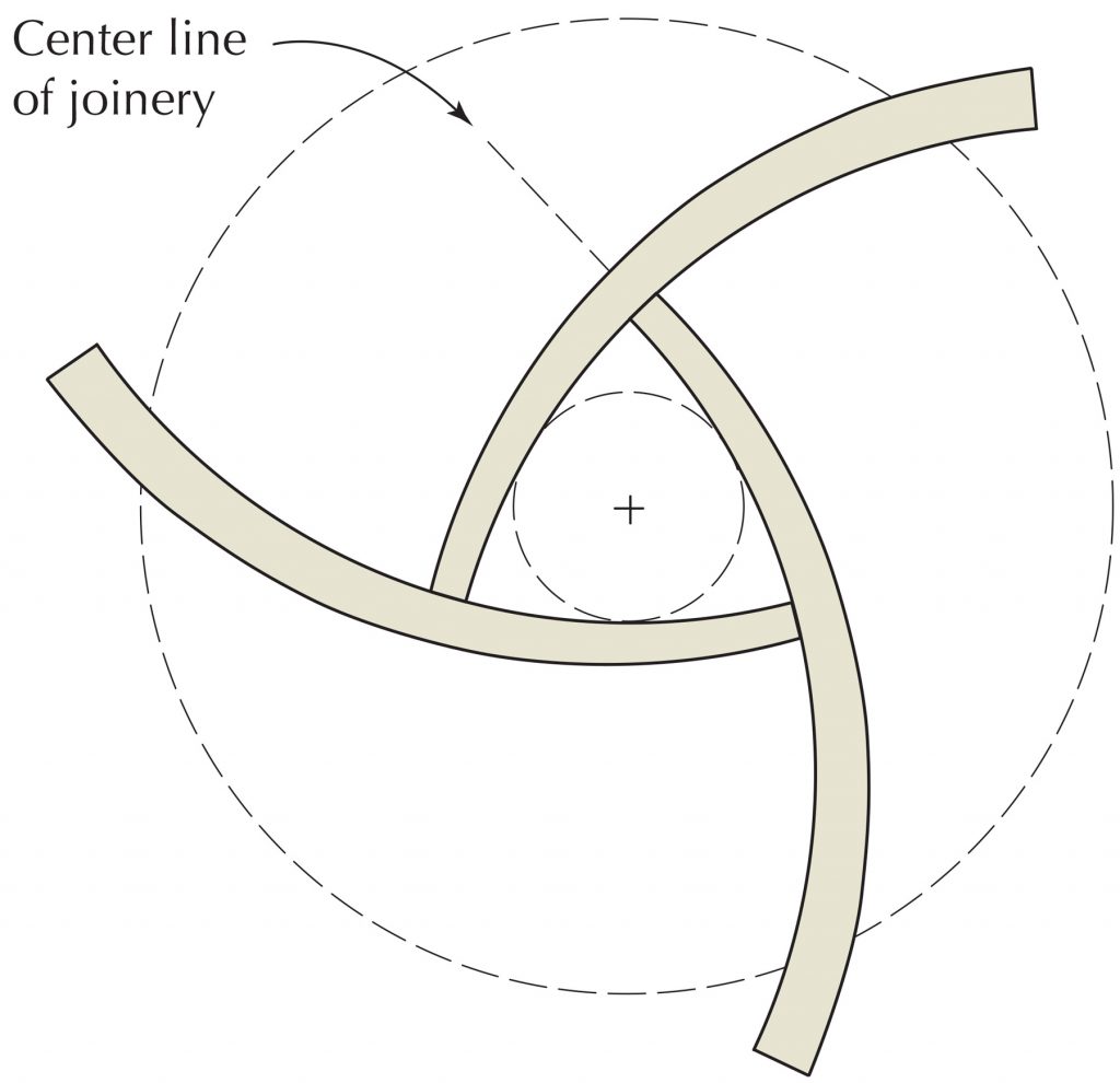
I started the full-size drawing with the diameter of the glass. I divided the circle in three parts by stepping off divisions around the circumference with the beam compass used to draw the circle. This makes six segments around the circle. I drew a line from the center to every other mark to define the three divisions.
The next decision to make was the size of the triangular center shape. I roughed in a few different-sized circles and swung different-sized arcs tangent to the circles. My full-size mock-up told me that the three curves, with a radius of 12″, should be tangent to a 41⁄4” diameter circle.
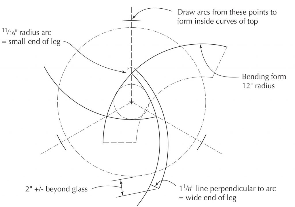
I drew the 41⁄4” circle and divided it into three segments, opposite the divisions in the large circle, to locate the tangent points. I swung 12″ radius arcs from these points to intersect with the lines dividing the large circle to locate the center points for the arc of the inside curve of the top rails. The outer curve of the rails is offset from the inner curve by a different dimension on each end: 11⁄16” where the curves intersect each other in the center, to 11⁄8” where the rails meet the legs, beyond the edge of the glass.
 I picked the length of the curves where they overhung the glass by blackening out the ends of the lines with electrical tape until the size looked pleasing to me.
With the design decisions made, I darkened in the curved lines and radius points I was going to use in construction. The bending form and all of the joinery jigs relate to the arcs and radius points so there is no guesswork. Because I had a full-size drawing, I could confirm all my shapes by comparing them to the drawing as I worked.
The drawing became the repository for all of my sketches as I figured out how to build the bending form, the jigs to cut the joints, and the cauls used to clamp the parts together during final assembly. The drawing is more than documentation; it is a valuable tool that is essential to have during the building process.

 Cutting the Joints
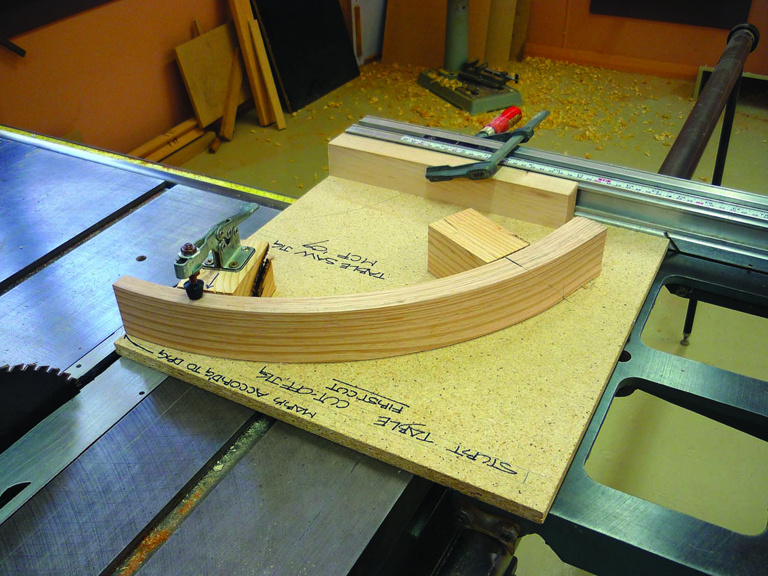
Cut-off jig. This table saw cut-off jig ensures the small end is cut square to the curve where it intersects a second rail.
I recommend making a table saw jig to cut the three parts to length. The length can be marked on one of the pieces right from the drawing as can the configuration of the table saw jig to hold them.
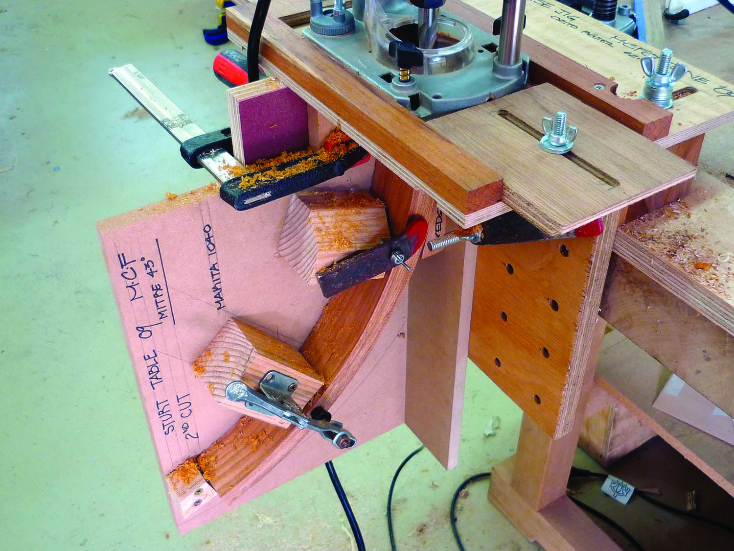
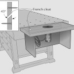
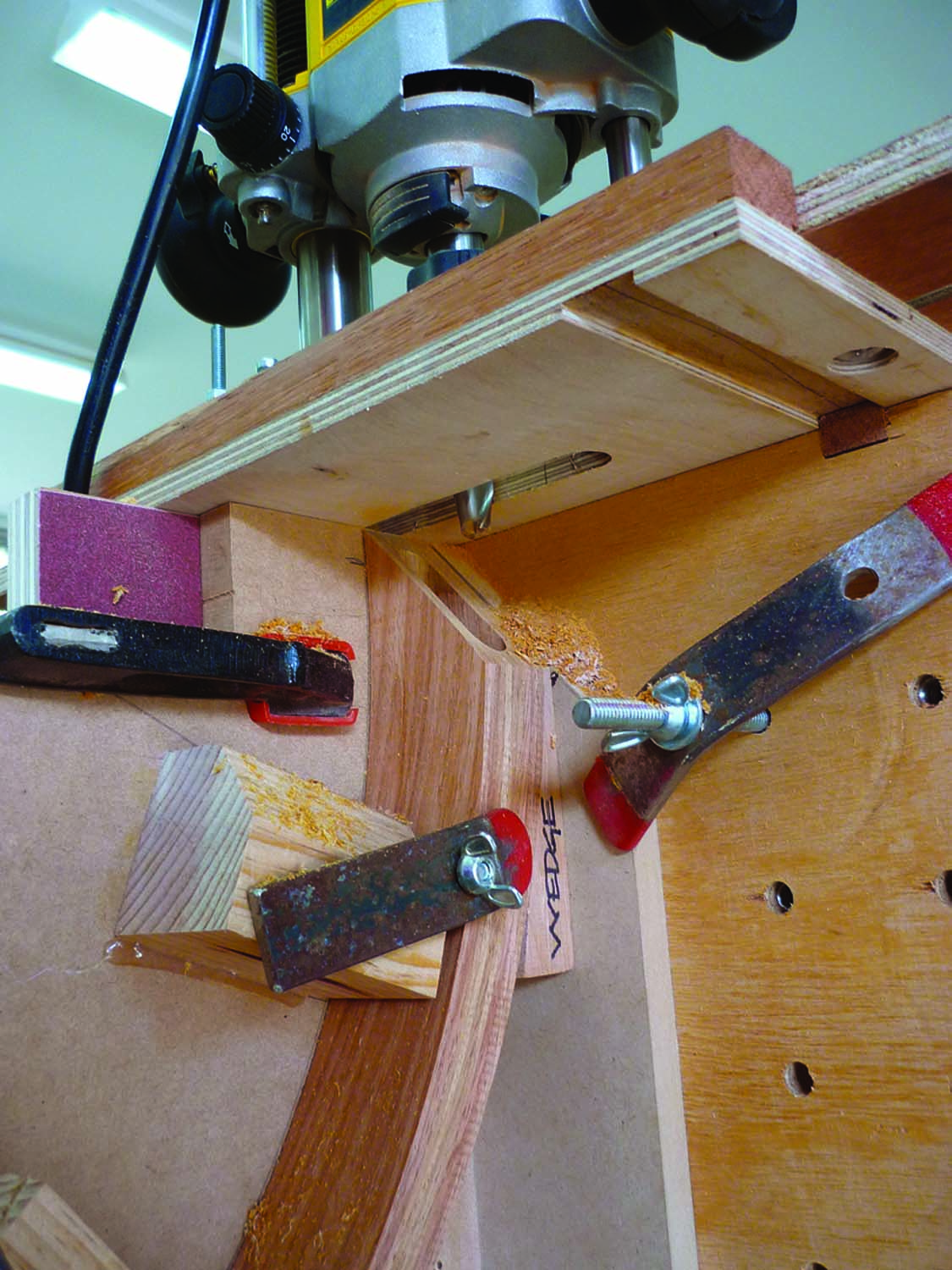
Two jigs in tandem. The miter saw jig is clamped to the shop-made mortising jig. A plunge router slides in a track and bores the mortise in the mitered face of the curved parts.
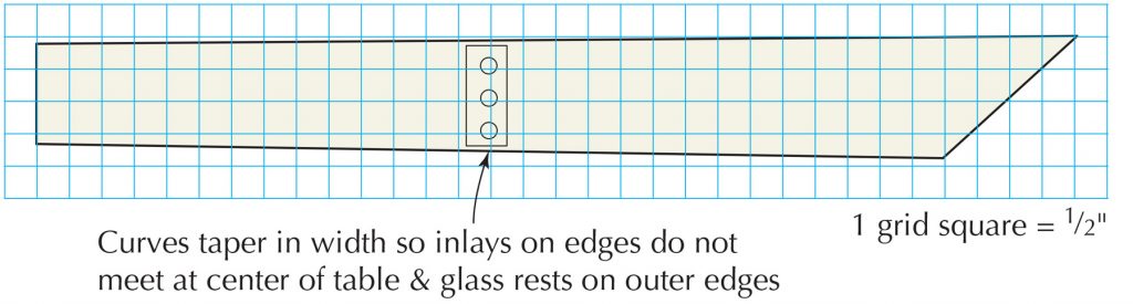
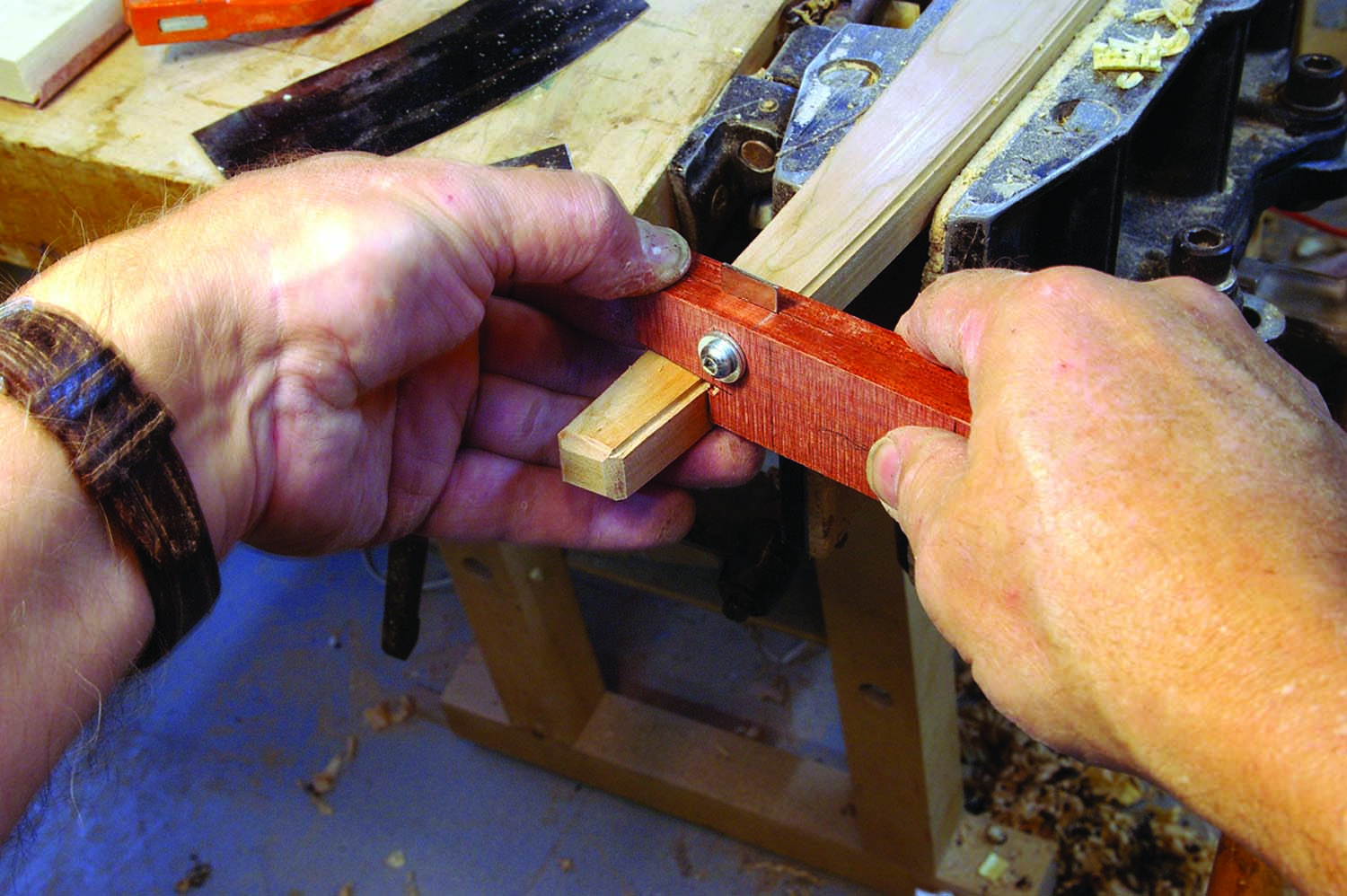
The curved rails taper in width, so the inlays on the joined edges at the center of the table don’t meet (the glass rests on the outer edges of the rails). Cut the thin end off first. This cut becomes the reference for the miter cut that is done on a miter saw.
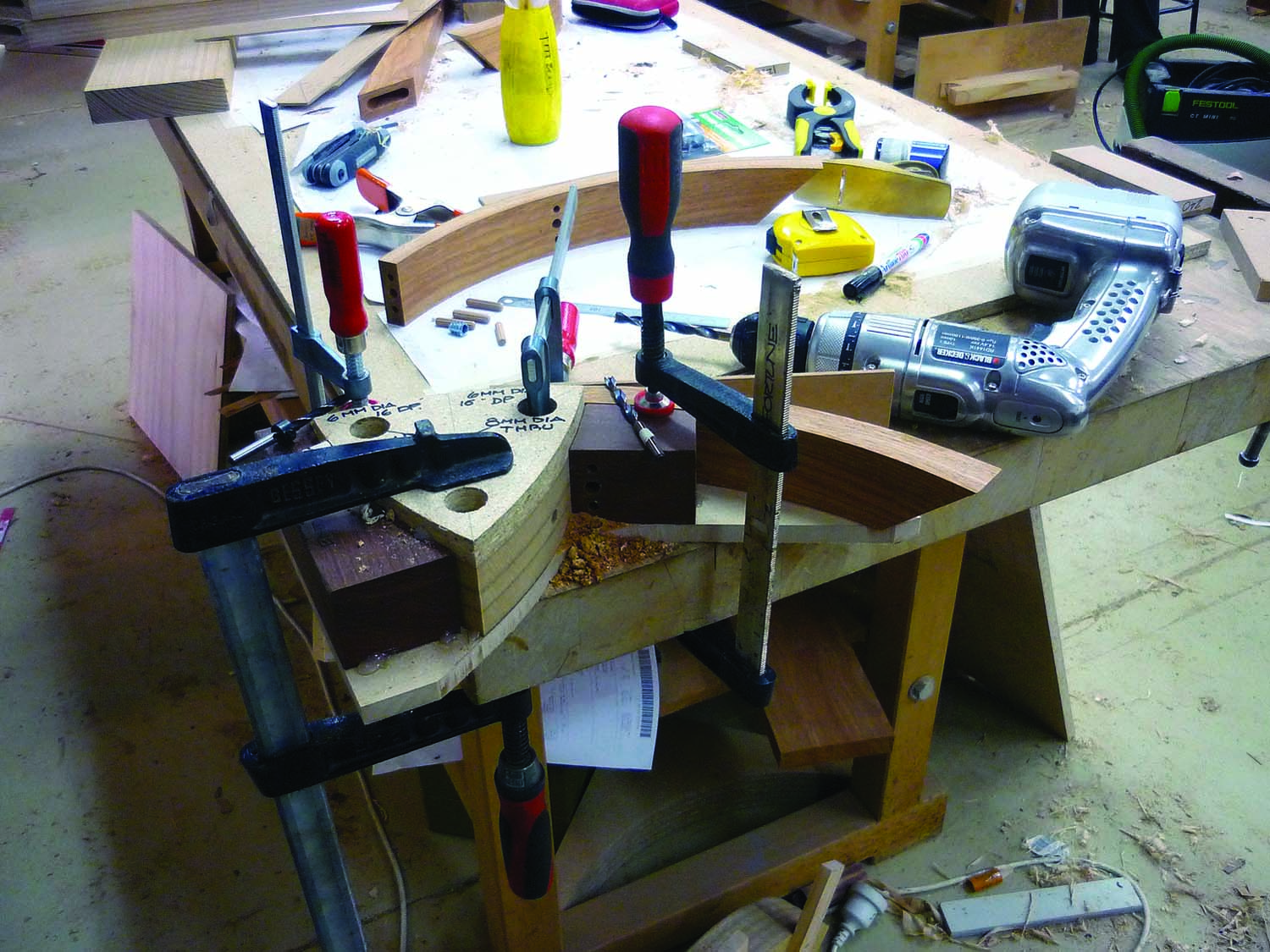
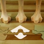
Center space. The center triangle shape is the center space between the curves. The curved parts are clamped to this shape. The blocks of hardwood are drill jigs. These holes were drilled on a drill press. The actual dowel holes are bored in the parts with a hand drill. The dowel holes are bored going in opposite directions through the same hole – this way the dowel holes always line up. I used metric drills for this variation of the table because I constructed it in Australia where the metric system is widely used. This one jig drills the side dowel holes as well as the matching end dowel holes.
The miter joint has to be strong so I’ve chosen to use a right-angled floating tenon. The curve and the corresponding leg at each joint have deep-bored mortises cut into the end grain. A right-angle Baltic birch plywood tenon – that not only bridges the joint but penetrates both members – is inserted.
Bottom up. Here is an underside view of the shop-made mortising jig with the miter saw cutoff jig and curved part clamped in place.
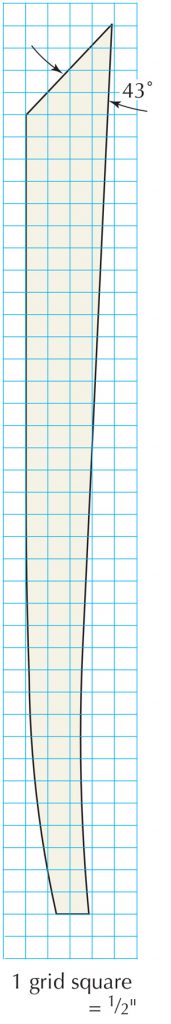
The rough mock-up suggested that the angle between the top curve and the leg should be about 86°, so the jig to hold the part on the miter saw will cut the thick end of the curve at 43°. Again, the drawing comes into play here. The radius point on the miter saw jig is identified so the cut is square to the curve. The jig should be securely mounted on the miter saw. I drilled and tapped the miter saw fence years ago for this purpose. Hold-downs should be installed and coarse sandpaper glued to the jig face so the part is held firmly during the miter cut.
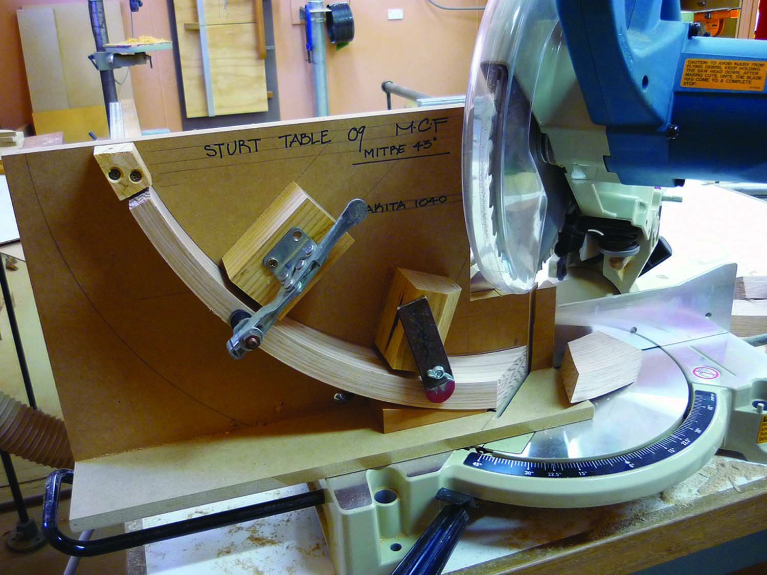
Mitered curve. The position of the curve is drawn on a piece of particleboard. It has been duplicated from the full-size drawing. The thin end offcut from the table saw is placed against the stop. The miter saw is set for 43°. A hold-down is necessary close to the miter cut. Coarse sandpaper is glued to the jig so the part is not pulled out of position as the cut is made.
Once the miter cuts have been made, the jig can be moved over to your mortise jig. I made this jig from Baltic birch plywood and I use it when I’m teaching in locations that do not have a mortise machine. I have used this jig for many years and recommend it as an inexpensive and effective means of cutting mortises.
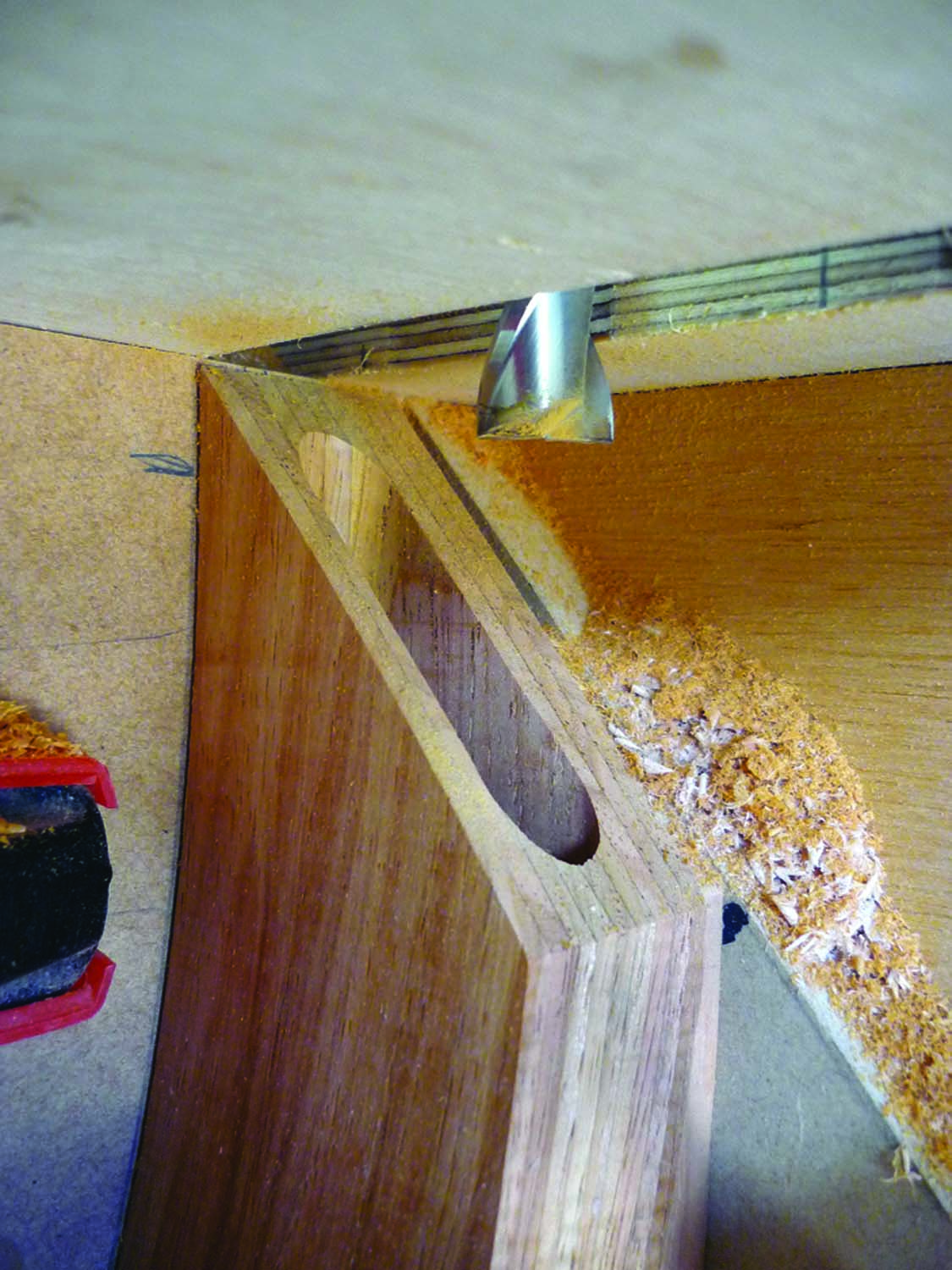
Clean mortises. A two-flute aluminum cutting end mill, when mounted in a plunge router, cuts a clean mortise. These bits are inexpensive (approximately $12) and are available from machine tool supply companies. Avoid three- and four-flute bits – they don’t like to plunge cut.
The mortise bits I use are actually used for milling aluminum. They are described as two-flute aluminum cutting end mills. These bits are very inexpensive and come in a wide variety of sizes. For this operation I am using a 3⁄8“-diameter x 4″-long high speed steel bit. The shank is 3⁄8“ diameter, an adapter sleeve can be purchased from Woodcraft to make it fit a 1⁄2“ collet plunge router. Light passes are best, plunging in only 1⁄8“ each time. A cautionary note, only the two flute bits will plunge, the three- and four-flute bits will not plunge.
Because the mortise is cut into the end of the curve, the mortise should be placed closer to the inside curve – otherwise it may penetrate the outside curve. The depth of the mortise is 21⁄4“.

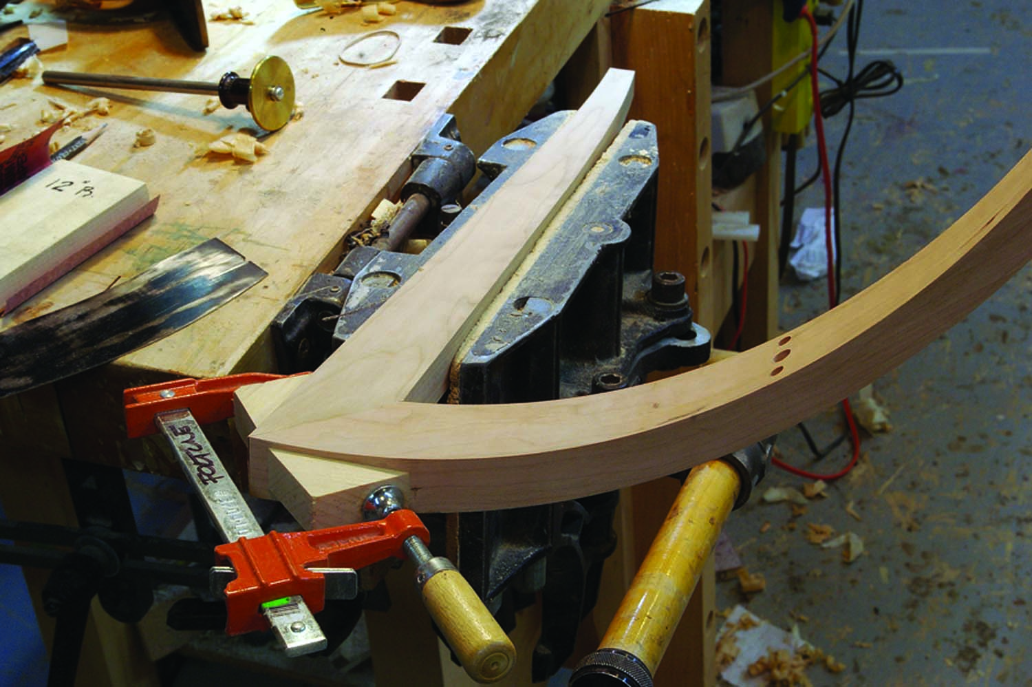
Taper. The taper is cut along the outside of the three legs.
The triple dowel joint on the thin end of the curves can be done now. The negative space created where the three curves come together becomes a mandrel to hold the parts during the boring operation. The drill guides made from blocks of wood are drilled on the drill press so the holes are tangent to the curve. Choose a hard resinous wood for your drill guides. The holes in the side of each curve and in the end grain are made with a hand drill through the block to keep the drill square. If care is taken, this type of drill jig will last for many years. Keep the dowels closer to the middle of the joint; this will allow the curved part to taper so it doesn’t sit flush at the intersection. I’ve made some of these tables to be assembled by the purchaser, so the middle hole is actually a metal fitting while the two outside holes are dry dowel joints.
The leg blanks can be made next. This small side table is about 20″ tall, the width of the leg blank is 17⁄8“ and the thickness is 13⁄16“. The extra thickness on the leg will allow for some hand fitting when the legs are joined to the top curves. Once the miter joint is cut and the mortise is deep bored, then the part can be band sawn to shape and tapered in thickness so the footprint at the floor is about 5⁄8“ square.
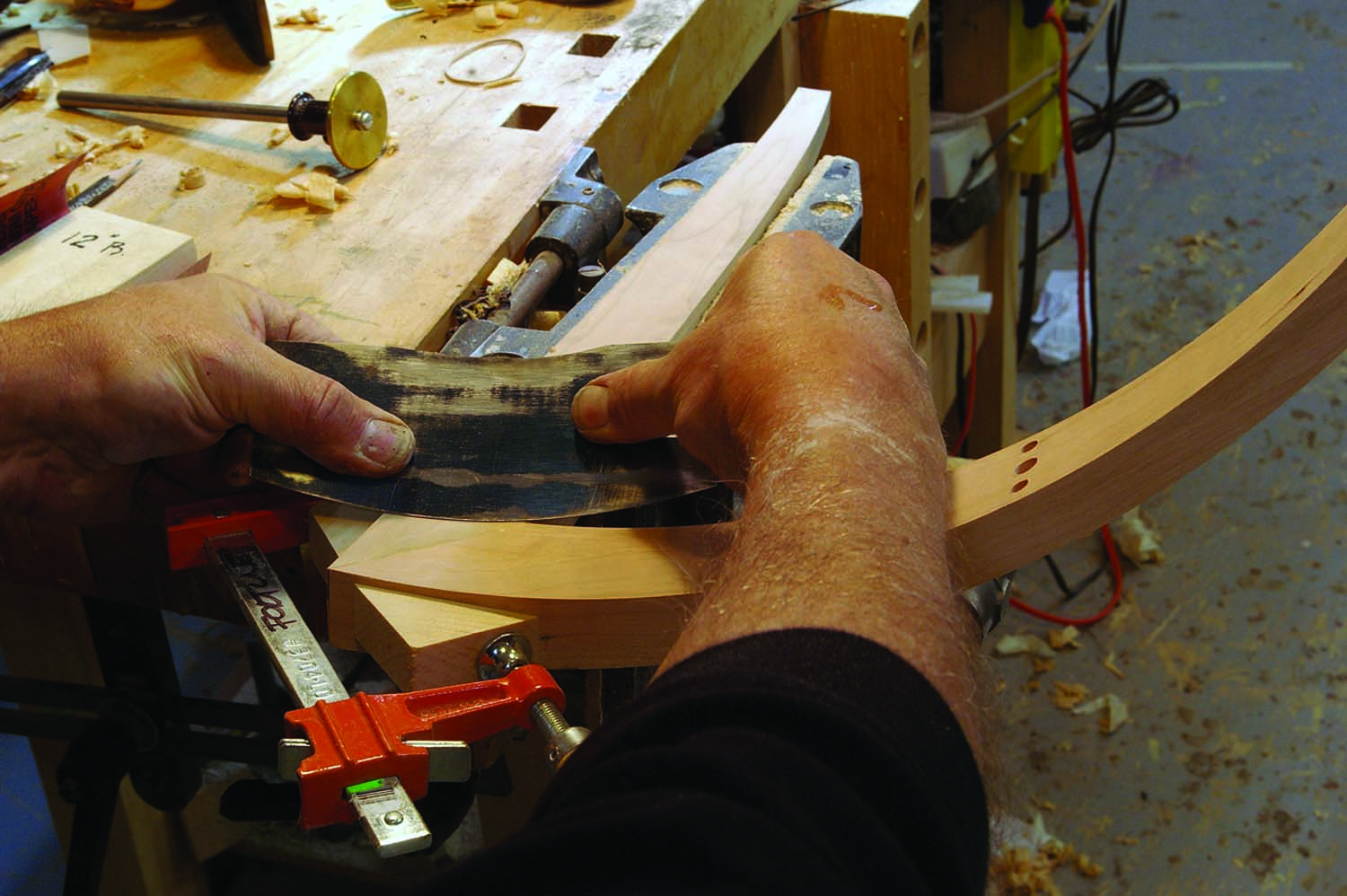
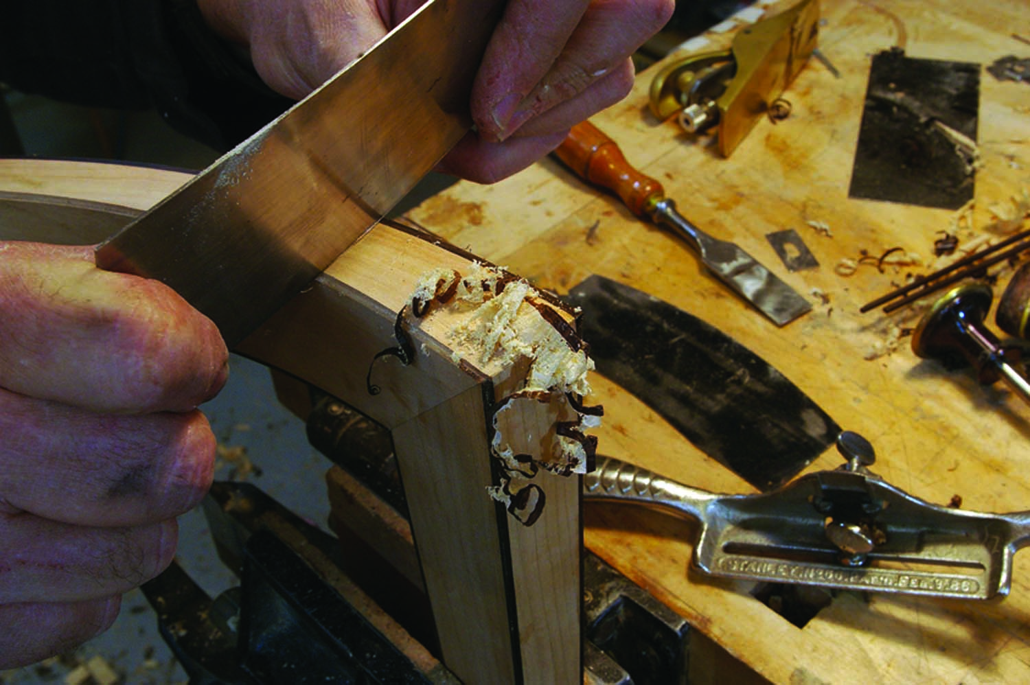
Scrape. The inside face of the leg, all the way to the floor, is card scraped to a concave surface to match the apron curve.
Dry-fit the miter joint and scribe the shape of the miter curve onto the miter face of the leg. The surface of the leg is actually concave on the inside and convex on the outside. I use a stiff card scraper shaped to the concave face and a block plane to create the convex face on each leg.
 Insetting the Ebony
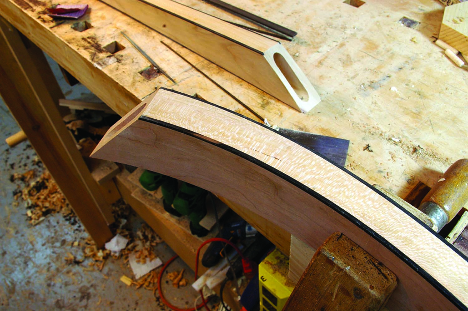
Inside, then out. The inside corners are done first.
Once all the miter joints have been flushed, the three assemblies are ready for the inlaid ebony. This is a two-stage process. The inside edges are done first. This way it is easier to get a perfect match where the ebony intersects. After the joints have been glued the outside two edges are done. It is easier to line up two ebony edges rather than four at once.
I thickness plane ebony strips to 3⁄32“. Each strip is about 1″ wide and 20″ long. I use a small benchtop planer with a fixed sled. I slowly rip the strips to 3⁄32“ on the band saw with a piece of hardboard underneath for zero clearance. This gives me lots of 3⁄32“ square ebony inlay.
Shop-made rabbetting tool. Some of the edges aren’t square where they intersect concave and convex surfaces. I’ve mounted small pieces of tool steel in hardwood blocks that mimic the angle at these edges to form the rabbets.
I use a rabbet bit on the router table to take some of the waste away then finish the rabbet with Stanley No. 66 beader and a shop-made beading tool that I’ve fitted with a square piece of hard steel. The ebony strips are hand sanded with a hard block to remove any oxidation immediately before gluing in place. This provides fresh unoxidized glue faces. Slow set cyanoacrylate glue is laid in the rabbet and the ebony is clamped in place with tape and elastic bands. Accelerator is sprayed on a Q-tip and run along the joint. The ebony is flushed off with a card scraper. Avoid sanding; the dust will be pushed into the surrounding lighter colored wood.
Don’t sand. Use a card scraper to flush the ebony. Avoid sanding, as the dust would contaminate the surrounding light wood.
Assembling the Miters
Curve transfer. The concave curve of the apron is transferred over to the leg.
I am very particular when gluing projects together. Something that went together well in a dry-fit may not be so cooperative when the glue is applied. When I am clamping curves or angles I always use glue blocks that give perfect perpendicular pressure across the glue line. In this case I’ll use pine cauls that have been glued with PVA right to the surface so the caul doesn’t slip when the clamp across the joint is tightened. The pine triangles are easy to remove. Use Titebond III for domestic woods and epoxy for exotic woods (or if your joinery has a gap or two).
Assembling the Dowel Joints
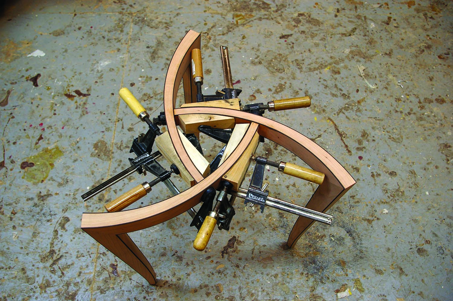
Cauls. Clamping cauls faced with #100-grit sandpaper are clamped to the curves. The clamping pressure must always be perpendicular to the glue line. I determined the shape of the cauls and direction of the clamping pressure from my full-size drawing.
Perpendicular clamping pressure is key here. All three dowel joints have to be assembled at the same time. I made custom cauls faced with #100-grit sandpaper for that purpose. Cleaning the inside corners can be difficult so I dry-fit the joint then sparingly use Waxilit around the joint. The glue is applied and left to squeeze out onto the Waxilit. The hardened glue is easily removed. The Waxilit residue is removed with denatured alcohol and a toothbrush. I’ve been using Waxilit for 15 years and have never had it detrimentally affect a finish.
One final detail: Chamfer the feet about 1⁄8“ all around so the wood doesn’t splinter when the table is dragged across the floor. This table base has a satin lacquer finish, but an oil finish is OK, too. The top is 3⁄8“ tempered glass with a polished pencil edge; it sits on three sticky back plastic “fish eyes” meant to hold glass tops in place.
Web Site: See more of Michael’s work on his web site.
Web Site: Find out when Michael is teaching at the Marc Adams School of Woodworking.
Michael is an internationally recognized furniture designer and builder, and a woodworking instructor. He lives and works in Lakefield, Ontario.
Here are some supplies and tools we find essential in our everyday work around the shop. We may receive a commission from sales referred by our links; however, we have carefully selected these products for their usefulness and quality.