We may receive a commission when you use our affiliate links. However, this does not impact our recommendations.
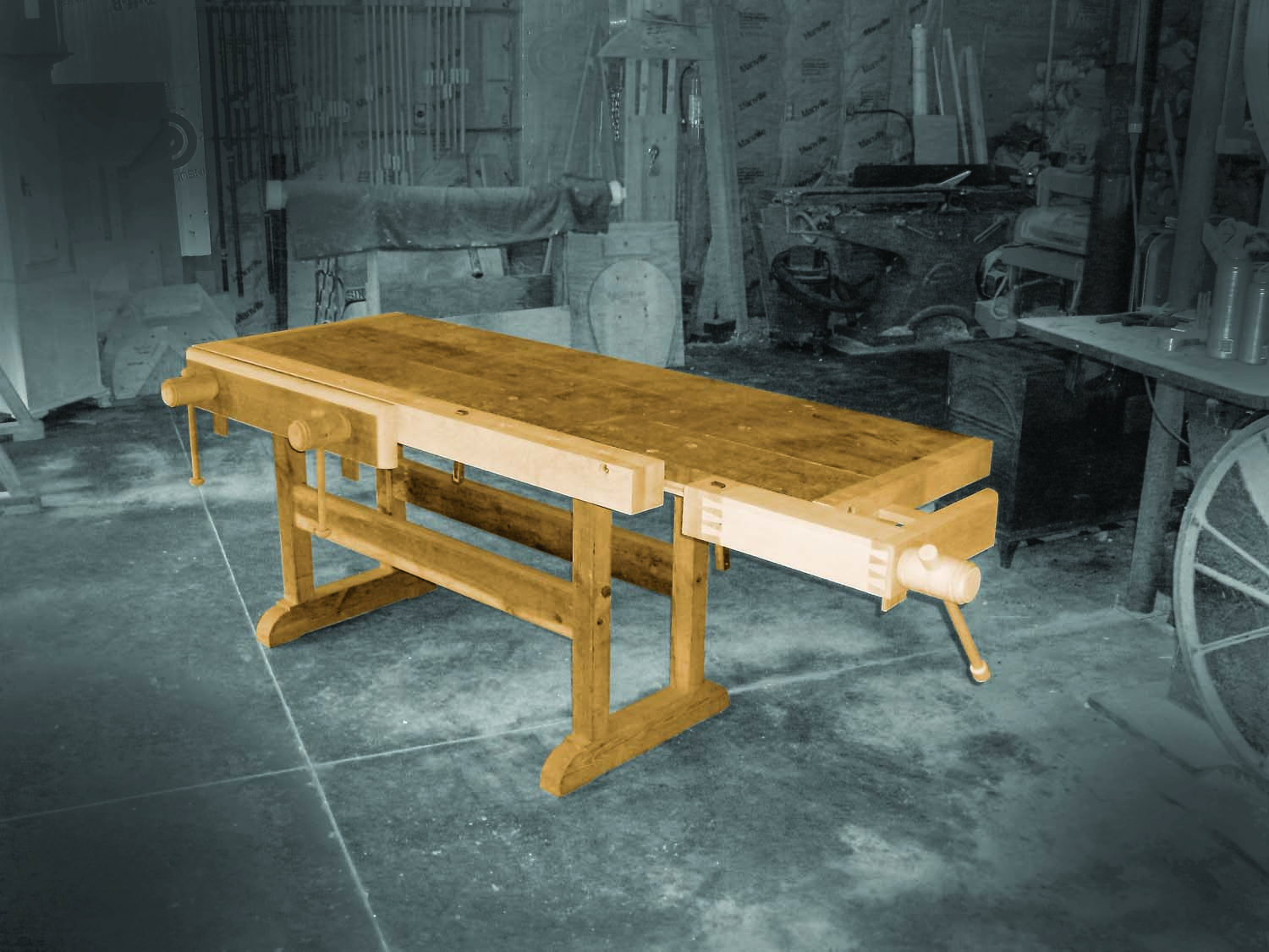
Built for hard usage, this traditional-style bench won’t vibrate like a kettledrum when you chop a mortise or skitter across the floor then you plane a board. It features a spacious 1-1/2″ thick solid-wood top and an extra-large double-screw face vise that can securely hold work of almost any size. Heavy timbers form the trestle-style base, which provides full-width support for the top and assembles with time-tested knock-down joinery—mortises, tenons and bed bolts. Build your bench of dense hardwood, such as hard maple or beech—or save money by using a combination of hardwoods culled from your lumber pile, as shown here. You’ll need a lathe and basic turning skills (or a wood-turning friend), along with a $50 wood-threading kit to create the wooden screws and threaded holes.
For additional functionality, consider outfitting this bench with a fully functional wooden tail vise. Doing so will make the bench 4″ deeper, and it requires altering the end caps and vise shown here, so it’s best to decide up front if you want to take on the challenge. The reward is that you’ll have built your own European-style woodworking bench entirely from scratch.
Make the Trestle Rails
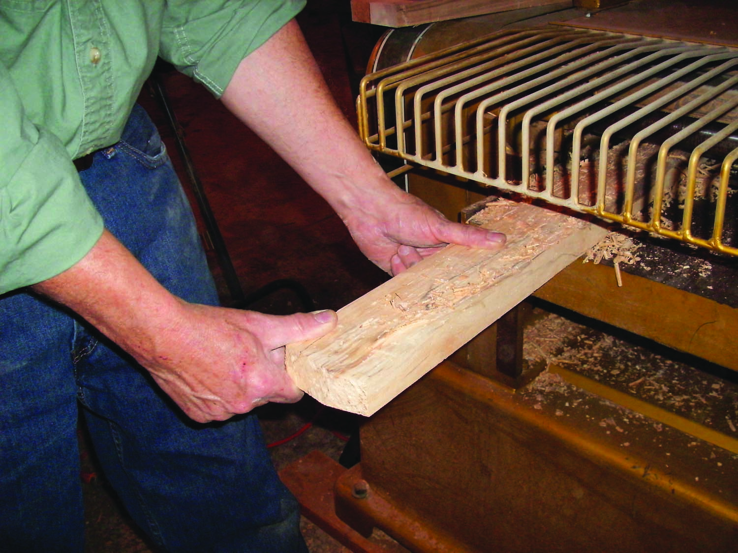
Photo 1. Mill 6/4 stock to make blanks for the trestles’ thick rails and stiles. Each part requires gluing together two blanks.
Make the 2-1/2″ thick trestle rails (A and B, Fig. A) from 6/4 stock milled to 1-1/4″ thickness (Photo 1). Each rail requires two milled blanks. Precisely cut the blanks to the rails’ final length and width (note that the bottom rails are 1″ wider).
Clamp the blanks together in pairs, flush at both ends. Then lay out the mortises (Fig. B) by using a square to draw lines across the top edge of each pair. Continue these lines across the outside face of each blank—make sure the edge and face lines are perfectly aligned. Match up a top and bottom rail for each trestle end—it’s important that the mortises align on both rails.
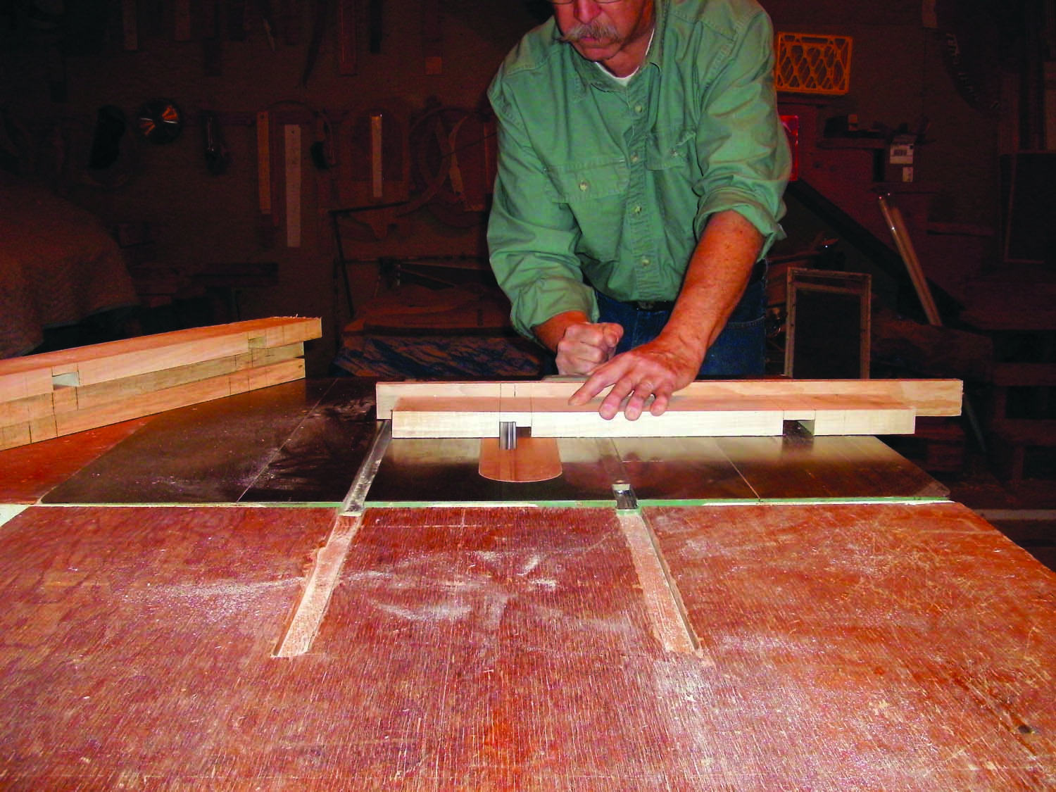
Photo 2. Cut dadoes in each rail blank. Precisely mark both edges of the dado blade on the miter gauge fence. Then simply align these lines with the layout lines on the blank.
Disassemble the blanks and cut 1-1/2″ wide x 3/4″ deep dadoes on both inside faces (Photo 2). Cut all the dadoes halfway deep; then raise the blade and go again to complete them. Assembling each pair of dadoed blanks creates the mortises. To make all the dado shoulders align perfectly, you might have to return to the saw and shave a bit off here and there. But when you make adjustments, remember that it’s important for the top and bottom rail mortises to align on each trestle assembly. Glue together each pair of blanks (Photo 3).
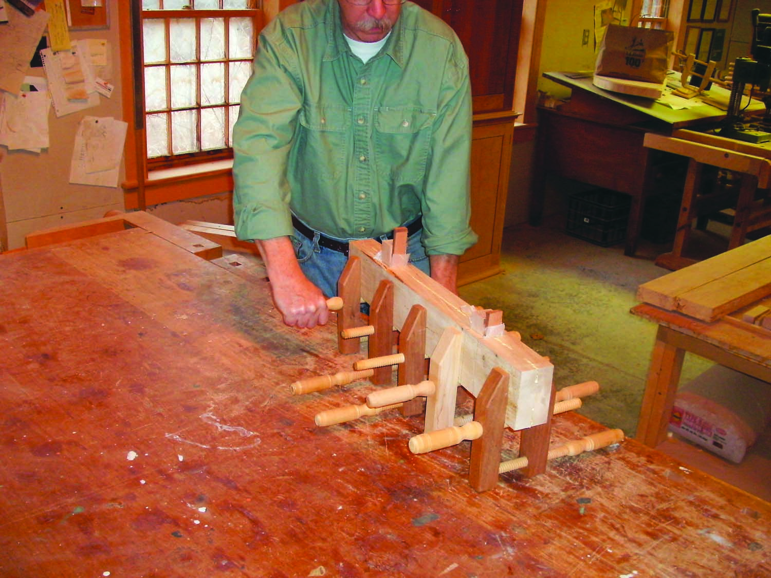
Photo 3. Glue a pair of dadoed blanks to make each rail. Spacers and wedges automatically align the dadoes to create through mortises.
Lay out the curves on the ends of the rails (Photo 4). On the bottom rails, cut 1/2″ deep notches to establish the decorative shoulders. Then use a compass or a coffee can to draw the 3″-radius curves. The top rails don’t have shoulders, just curves. Lay out the feet on the bottom rail. Then cut the curves and the feet on the bandsaw.
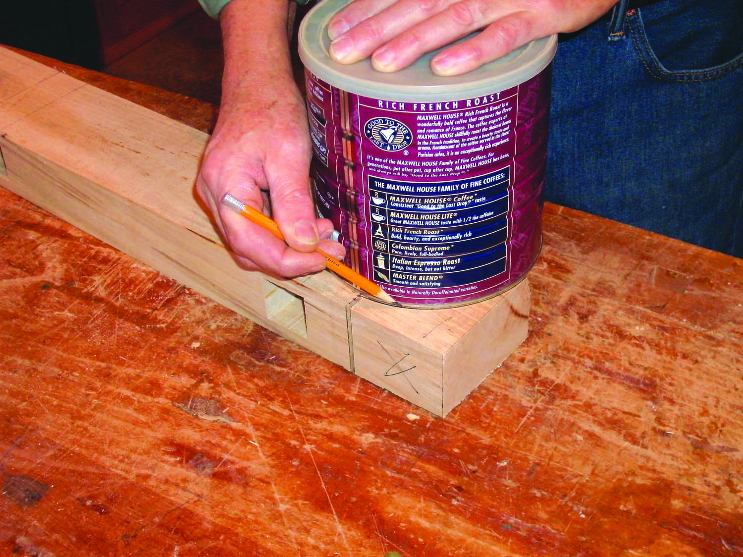
Photo 4. Use a coffee can to lay out the curved foot on each rail after cutting a notch to establish its shoulder.
Make the Trestle Stiles
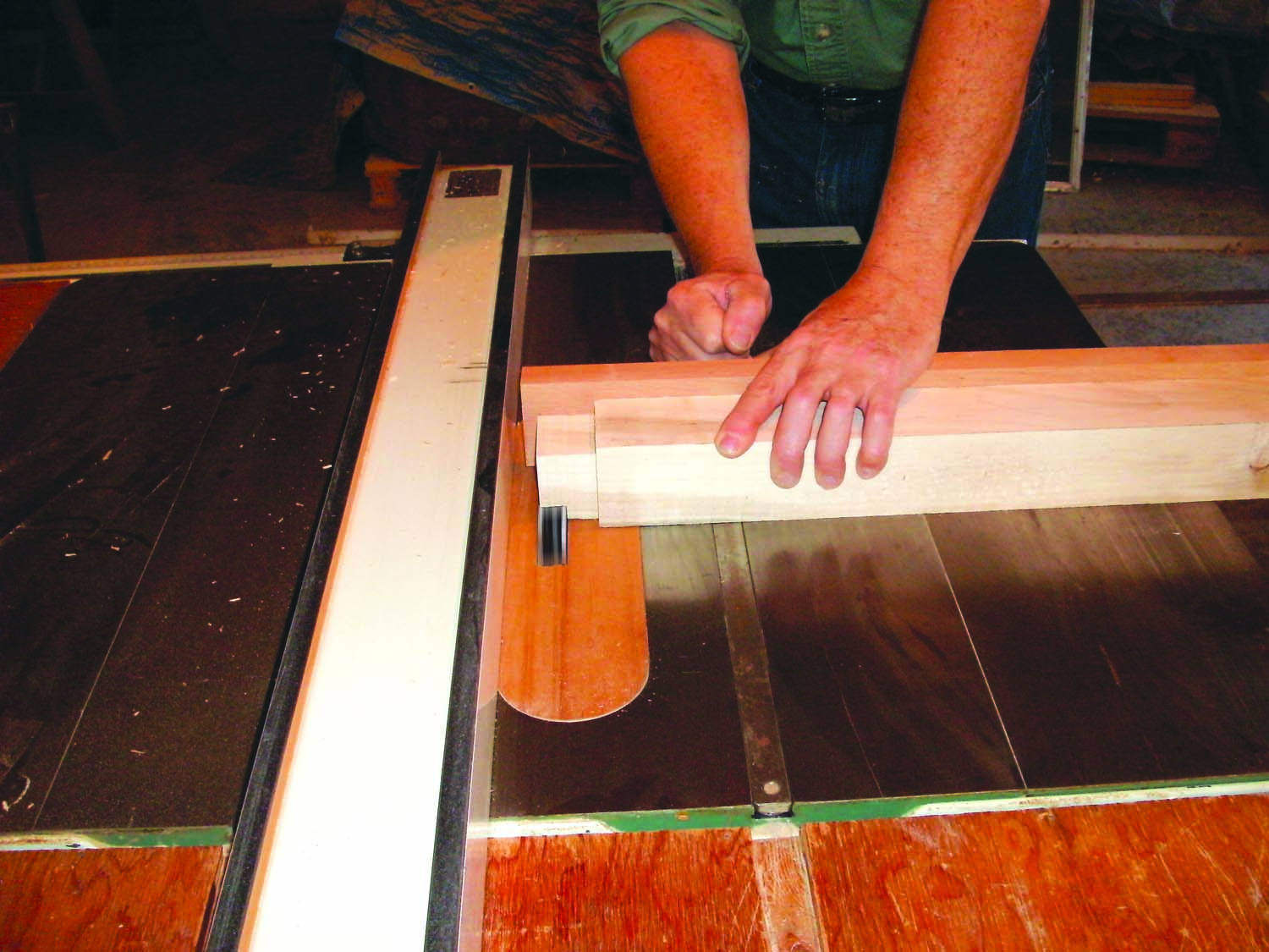
Photo 5. Cut tenons on the stiles using the miter gauge outfitted with a long support fence. Use the rip fence to establish the shoulders. Make half-depth passes on all four sides, then raise the blade and go again.
As before, mill and glue together 1-1/4″ thick blanks made from 6/4 stock to create the stiles (C). This time, wait until the stiles are glued together before cutting them to final length. Then cut 1-1/2″ square x 1-1/2″ long tenons on both ends of all the stiles (Photo 5). Test-fit the joinery between the stiles and rails in both trestle assemblies and make any necessary adjustments. Then mark each mortise and tenon so you’ll be able to correctly reassemble each trestle. In addition, mark the outside faces of each pair of stiles. Then disassemble the trestles.
Lay out holes for the bed bolts and mortises for the stretchers on the stiles. Using a square, strike a perpendicular line across the outside face of each stile, 12″ up from its bottom shoulder. Mark the center of this line to locate the center of the bed bolt hole. Carry the perpendicular line around to the stile’s inside face and mark its center point. Then lay out a 3/4″ wide x 4″ long mortise that’s centered on this point.
Cut the mortises using a mortiser or a drill press outfitted with a mortising attachment. You can also create the mortises using a drill press equipped with a 3/4″ Forstner bit. Install a fence on the drill press and set it to center the bit on the mortise. Set the drilling depth to 1-1/8″ and drill a series of overlapping holes to rough out the mortise. Then square the shoulders by hand (Photo 6).
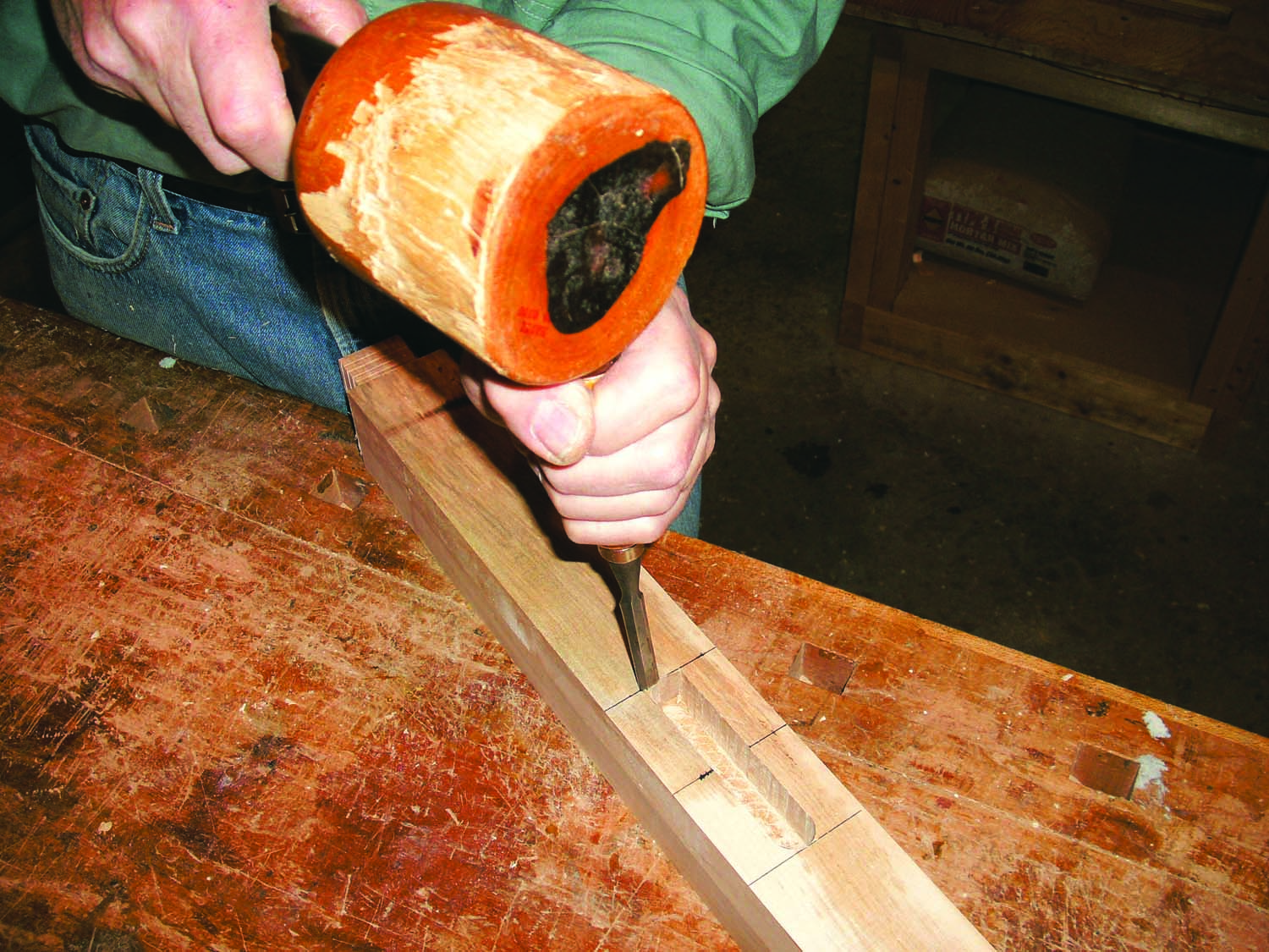
Photo 6. Cut a stopped mortise for the stretcher in each stile. Square the shoulders after roughing out the mortise by drilling a series of overlapping holes.
The bed bolt holes are countersunk, so start by using a 1″ dia. Forstner bit to drill a 1-5/16″ deep hole at the center point marked on the outside face of each stile. Here’s a tip: When the drill bit is centered on the layout line of the first stile, make a tick mark on the fence where the layout line touches it. The tick line allows you to quickly position the remaining stiles for drilling.
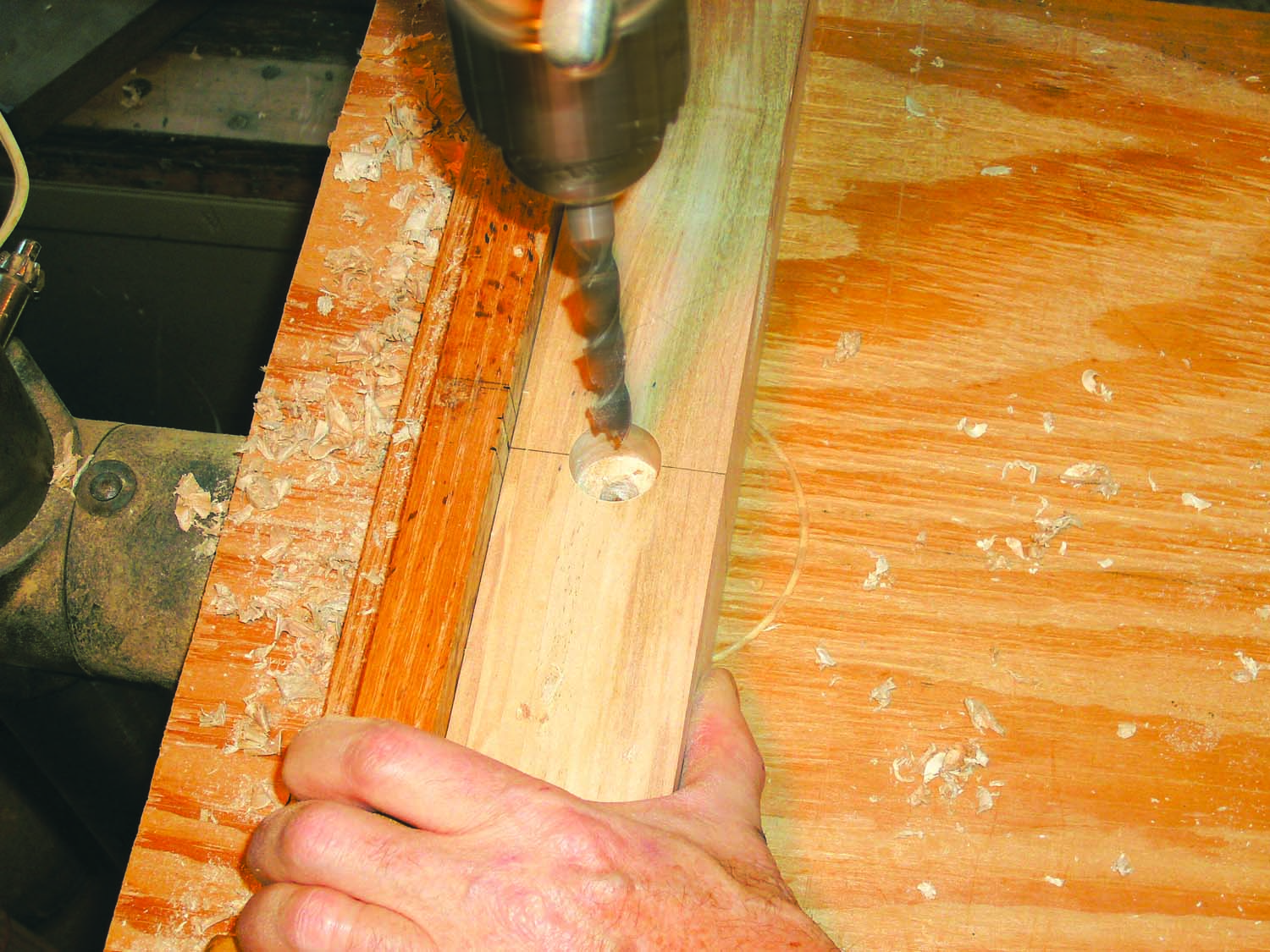
Photo 7. Drill a stopped countersink and a through shank hole for a bed bolt opposite the stretcher mortise in each stile.
Install a 7/16″ diameter drill bit to drill the shank holes. Use the tick mark on the fence to position each stile. Before drilling, make sure that the bit engages the indentation left by the 1″ Forstner bit (Photo 7); the hole must be centered in the mortise on the stile’s opposite face.
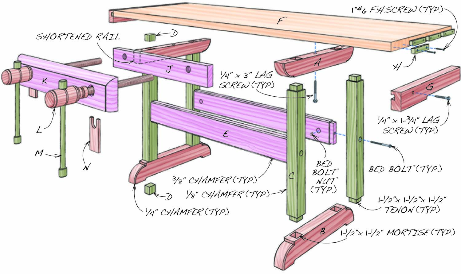
Fig. A. Exploded View
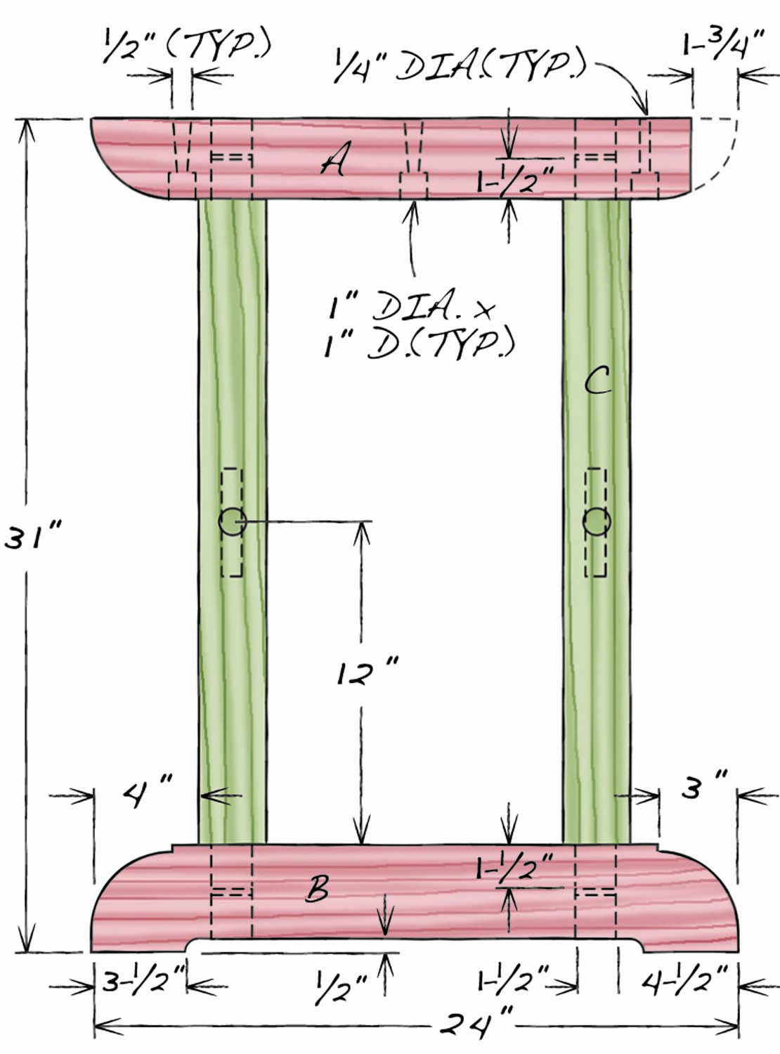
Fig. B. Trestle Dimensions
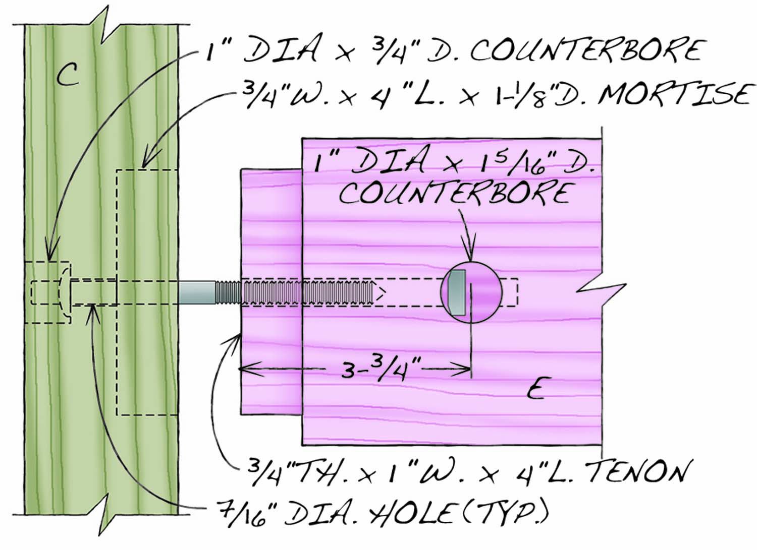
Fig. C. Bed Bolt Joint
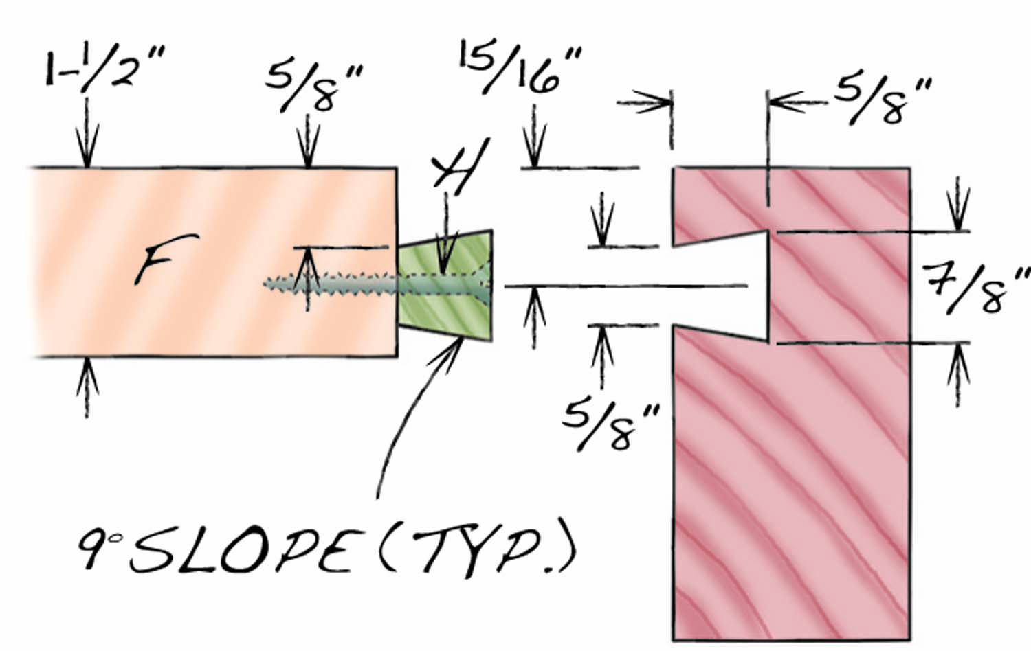
Fig. D. End Cap and Key Dimensions
Cut List
|
Workbench with Federal-Style Vise Overall Dimensions: 32-1/2″ H x 80″ L x 30-1/2″ D |
||||
|
Part |
Name |
Qty |
Material |
Th x W x L |
|
A |
Top rail |
2 |
Hard maple |
2-1/2″ x 3″ x 24″ (a) |
|
B |
Bottom rail |
2 |
Hard maple |
2-1/2″ x 4″ x 24″ |
|
C |
Stile |
4 |
Hard maple |
2-1/2″ x 2-1/2″ x 27″ (b) |
|
D |
Fill block |
8 |
Hard maple |
1-1/2″ x 1-1/2″ x 1-3/4″ (c] |
|
E |
Stretcher |
2 |
Hard maple |
1-1/2″ x 5″ x 45″ (d) |
|
F |
Top |
1 |
Oak |
1-1/2″ x 24″ x 76-1/2″ |
|
G |
End cap |
2 |
Oak |
1-3/4″ x 3″ x 24″ |
|
H |
Key |
10 |
Hard maple |
5/8″ x 7/8″ x 5″ |
|
J |
Fixed jaw |
1 |
Oak |
1-1/2″ x 4-1/2″ x 33-11/16″ |
|
K |
Adjustable jaw |
1 |
Oak |
1-1/2″ x 6″ x 35″ |
|
L |
Screw |
2 |
Hard maple |
3″ dia. x 21″ |
|
M |
Handle |
2 |
Hard maple |
1-1/4″ dia. x 14″ |
|
N |
Garter |
4 |
Hard maple |
3/8″ x 2-3/4″ x 6″ |
|
Notes (a) Shorten the front of one top rail by 1-3/4″ to accommodate fixed jaw fill strip. (b) Length includes 1-1/2″ tenons on both ends. (c) Trim top rail fill block to 1-1/4″ L before installation. (D) Length includes 1″ tenons on both ends. |
||||
Glue the Trestle Assemblies
Install fill blocks (D) in all the mortises. Shorten the left trestle assembly’s top rail by 1-3/4″ to accommodate the double-screw face vise that mounts on the front of the bench. Drill countersunk shank holes through both top rails for the lag screws used to mount the bench top. Widen the ends of the center and back holes by working the bit front-to-back to allow the top’s seasonal movement. Chamfer the rounded ends on the top rails, the feet on the bottom rail and all the stiles’ long edges. Match up the stiles and rails, make sure all the parts are correctly oriented and then glue together the trestle assemblies (Photo 8).
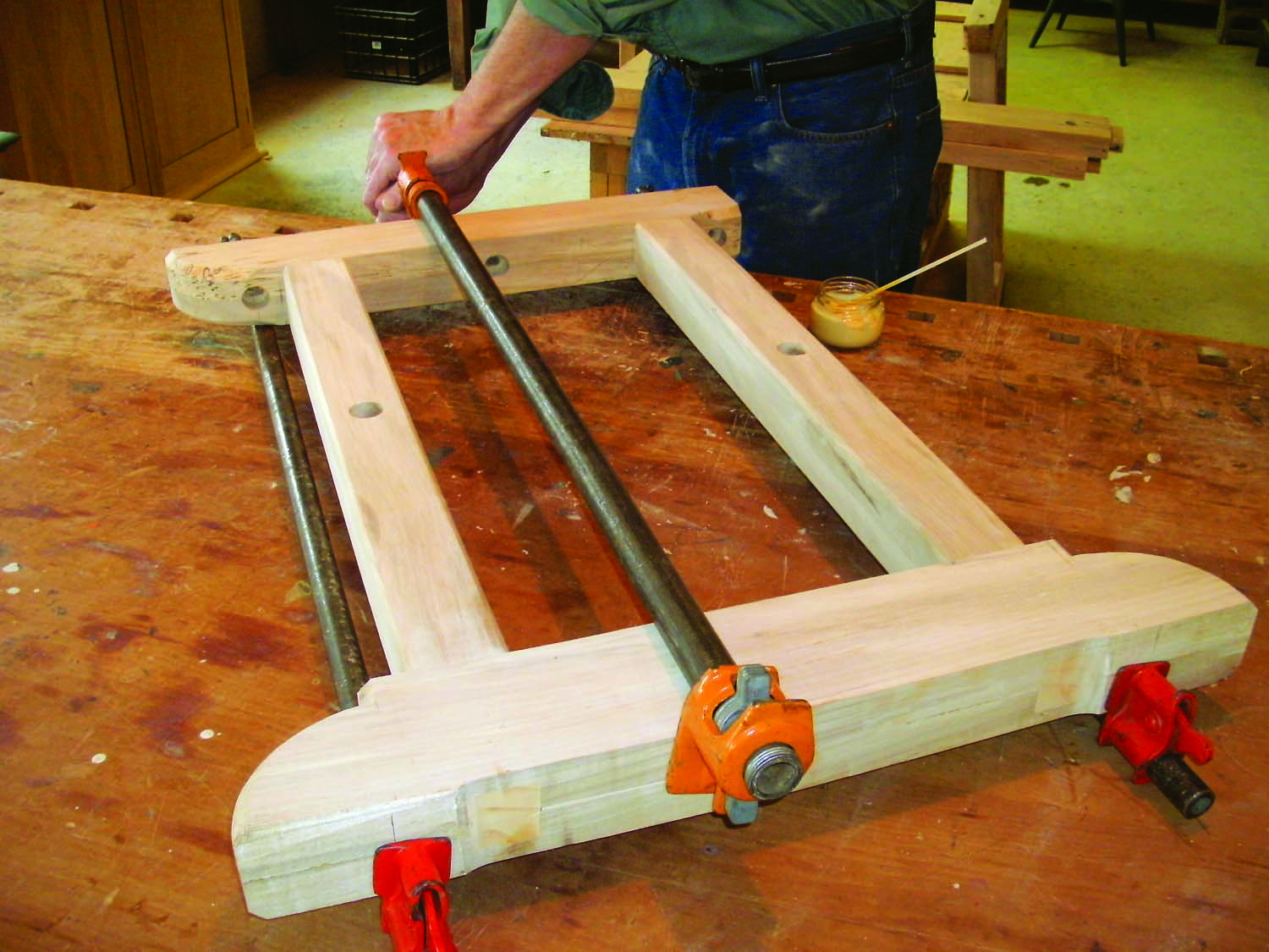
Photo 8. Glue together each trestle after drilling mounting holes for the top, sawing out the feet, and cutting back the front end of the top left rail 1-3/4″ to accommodate the vise.
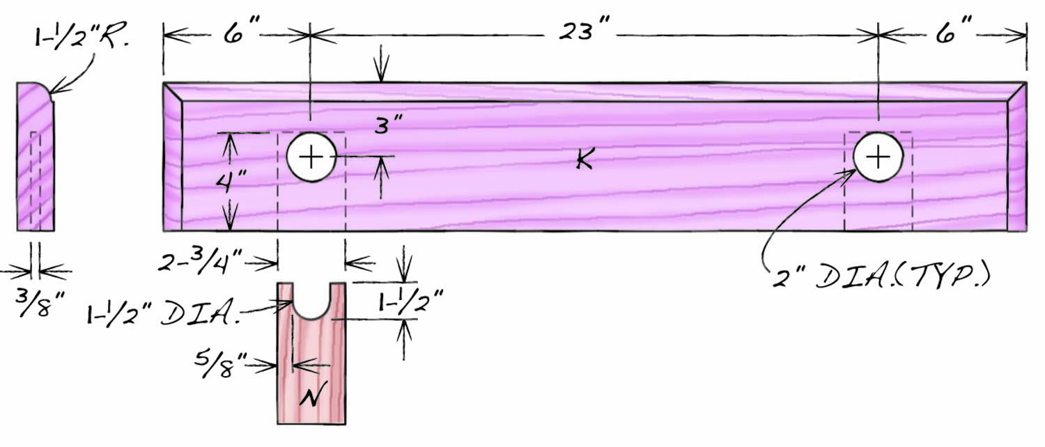
Fig. E. Adjustable Jaw
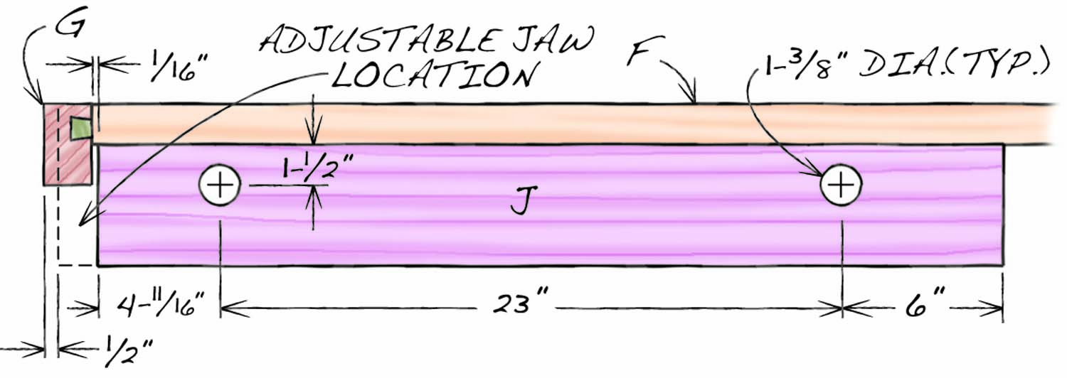
Fig. E. Fixed Jaw
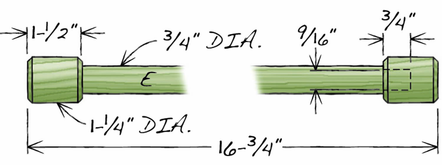
Fig. F. Wooden Screw Handle
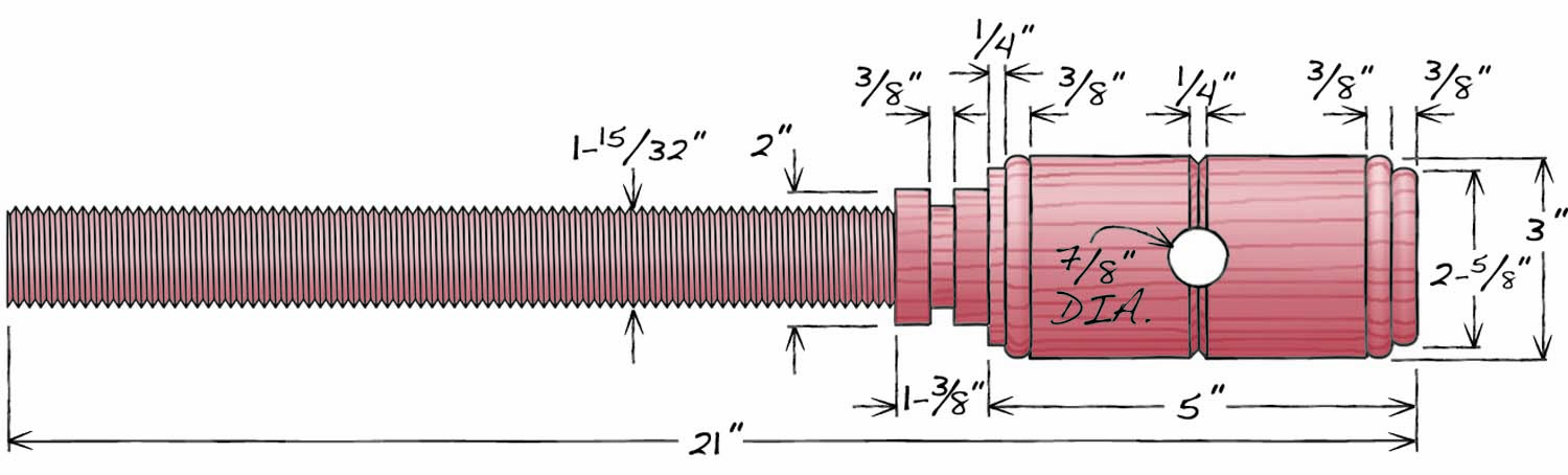
Fig. F. Wooden Screw
Make the Stretchers
Mill the two stretchers (E) that connect the trestles to final dimensions. Then locate and drill the bed bolt shaft holes in the ends. Using a square, mark a centered line across the end grain on the 5″ wide stretcher—after the stretcher’s tenon has been cut, this hole will align with the bed bolt hole in the stile. Continue the centered line about 6″ onto the stretcher’s inside face.
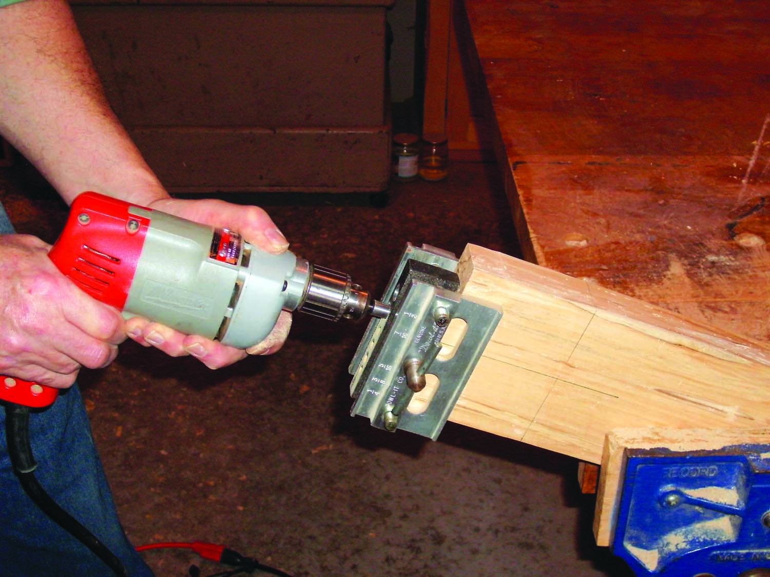
Photo 9. Drill a centered shank hole in the end of each stretcher for the bed bolt. Use a self-centering doweling jig to start this deep hole and remove the jig to finish drilling it.
Align a self-centering dowelling jig on the line marked on the end of the stretcher and drill a 7/16″ dia. hole into the end grain as deeply as the drill will go (Photo 9). Note: The jig is great for drilling a hole square to and centered on the board being drilled, but it prevents the bit from drilling deep enough for the bed bolt. So, remove the jig and then, using the hole just drilled as a guide, drill as deeply as the bit allows.
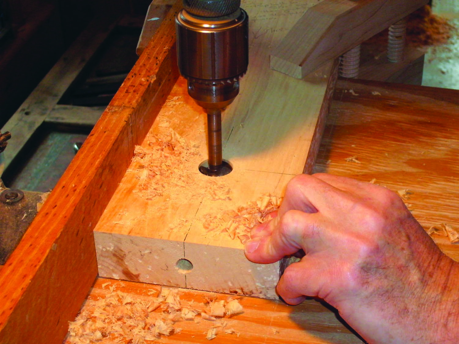
Photo 10. Drill a stopped hole for the bed bolt nut. Center this hole on the bolt’s shank hole and drill just deep enough to make the hole in the nut concentric with the shank hole.
Next, drill holes to house the bed bolt nuts (Photo 10). Located on the inside faces of both stretchers, these holes intersect the shank holes drilled in the ends of the stretchers. Mark a point on the centerline drawn earlier, 3-3/4″ from the end of the stretcher. At that point, use a 1″ Forstner bit to drill a 1-1/4″ deep stopped hole.
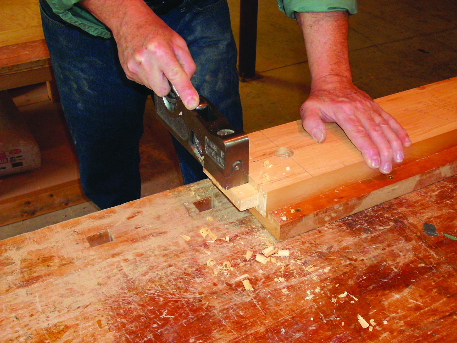
Photo 11. Size the stretchers’ tenons to slide easily into the mortises. These joints aren’t glued. The tenons simply position the stretchers until the bed bolts and nuts lock the parts together.
Complete the stretchers by chamfering their long edges and cutting 1″ tenons on both ends. For long pieces like these, it’s best to use a crosscut sled with a long fence for support, but you can also use the miter gauge setup shown earlier. Lay each stretcher flat to cut the tenon cheeks. Lower the blade and stand the stretcher on edge to cut the tenon’s ends. Note: The tenons are only used for positioning, so it’s OK to make them slightly undersize (Photo 11). Chamfer the ends of the tenons, to make them even easier to install.
Tightening the bed bolts with a bed bolt wrench or socket wrench draws the stiles and stretchers tightly together and holds the assembled base together.
Assemble the Base
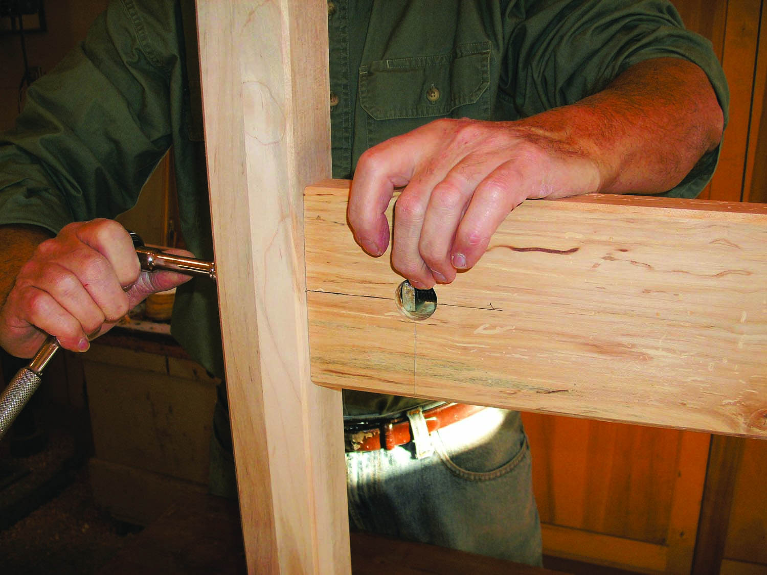
Photo 12. Install the bed bolts to assemble the base. Slide each bolt through the stile and the stretcher. The square bed bolt nut virtually holds itself in position while you tighten the bolt.
Stand one of the trestles upright and install one of the stretchers, positioned so the hole for the nut faces inside. Push a bed bolt through the holes drilled through the stile and stretcher until you can just feel the point entering the hole for the nut. Slip a bed bolt nut in the hole and align it with the point of the bolt. Orient the nut’s convex face towards the bolt, so it will seat against the hole’s curved wall. Hold the nut steady and use a wrench to tighten the bolt. (Traditionalists will insist on using a bed bolt wrench to properly engage the bolt’s square head, but a socket wrench will do.) As the bolt threads, the square-sided nut will bear against the bottom of the stopped hole, so you don’t need a wrench to hold it, only finger pressure (Photo 12). Continue to tighten the bolt until the stretcher’s tenon shoulders draw tight against the stile. Repeat these steps to install the other stretcher on the trestle. Then attach the other trestle to complete the base. Reverse the process to disassemble the base.
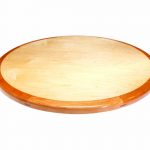
Make the Bench Top
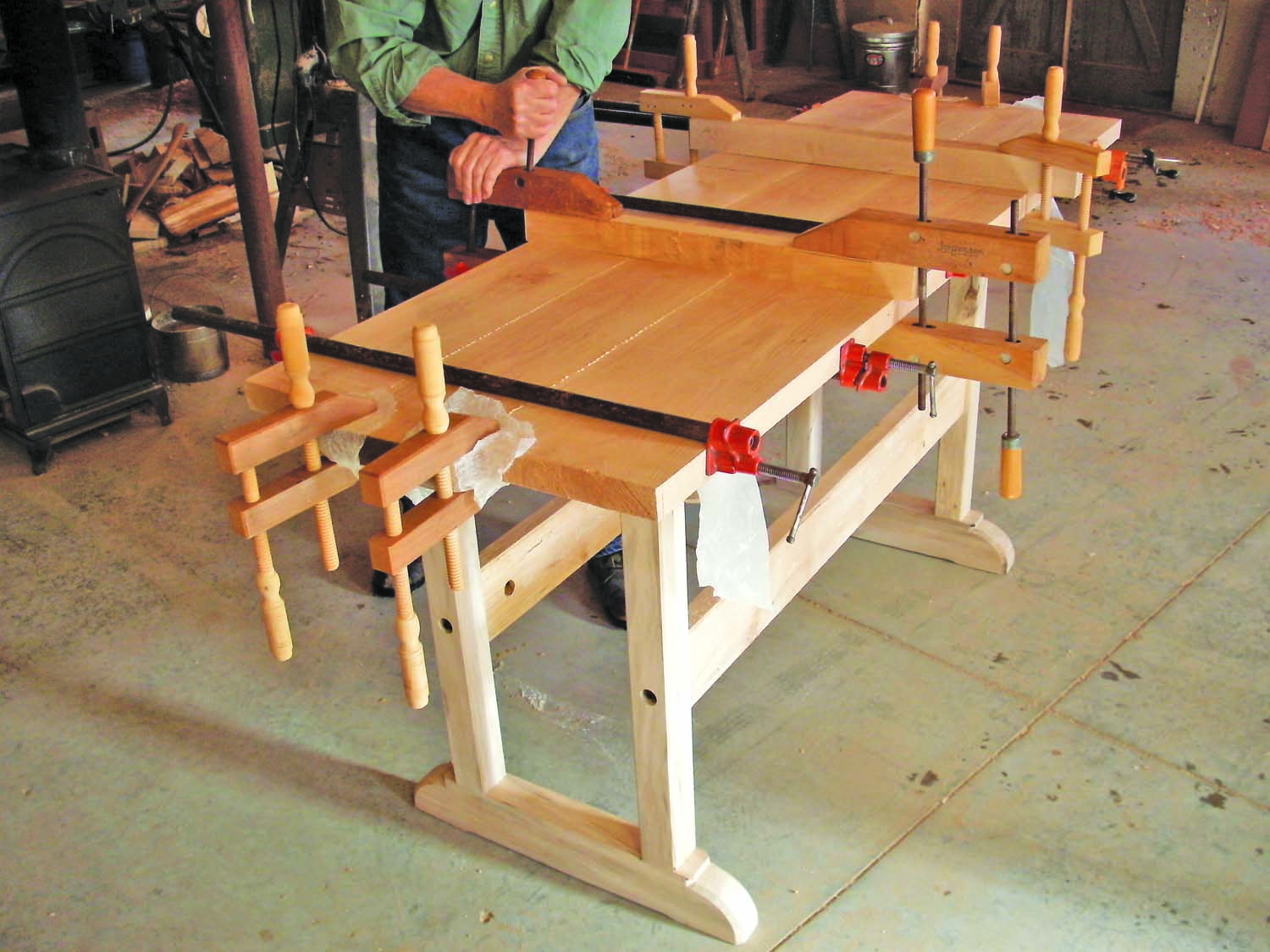
Photo 13. Glue up the top after making sure the boards’ edges are square and flat. Then cauls and clamps will easily keep the top flat and the joints aligned. Use the base as an assembly table.
Thickness-plane boards for the top (F) and joint their edges square. Note: If the edges aren’t square, the top won’t glue up flat. If you don’t have a suitable jointer, you can square the edges on the tablesaw, using a glue line rip blade (see Sources). Glue the boards together (Photo 13). Then trim the ends square (Photo 14). When you rout, position the straightedge with a sufficient overhang to support the router at the beginning of the cut and stop short, so you don’t blow out the edge at the end of the cut. Flatten the nub that’s left by sanding with a block or using a hand plane, working from the outside edge to the center.
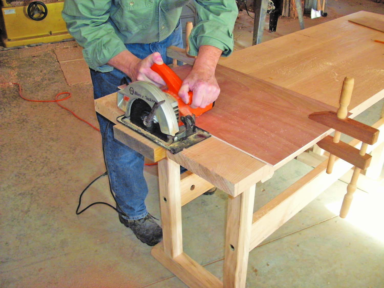
Photo 14. Square the top’s ends, using a straightedge. Start by cutting with a saw. Then switch to a router equipped with a flush-trim bit and make a shallow pass to clean the edge.
Lay the top bottom-side up to install the base. Position the base so its left trestle is 7″ away from the end of the top and its shortened top rail is 1-3/4″ back from the front edge. Then make sure the right trestle’s top rail is flush with or slightly behind the front edge. Mark the mounting screw locations and drill pilot holes. Then install the screws and turn the bench right-side up.
I positioned the top with about 7 inches over hang on the bench’s left front. I bolted the front plank to the base with two 1/4” x 2 1/2” lag bolts. Widen holes about 1/2 at the top.
Install the End Caps
End caps (G) secured by dovetail-shaped keys (H) keep the top flat while allowing its seasonal movement (Fig. D). Mill 8/4 stock to 1-3/4″ thickness to create the end caps. Cut a pair of blanks to width and length and drill a single countersunk pilot hole for a 3/8″ x 6″ lag bolt in each one. Then use the tablesaw to cut a 7/8″ wide dovetail-shaped groove on the inside face of each blank, starting 5/8″ from its top edge (Fig. D). Tilt the blade 9˚ to cut the angled shoulders. Then install a dado set to remove the waste. You can lighten the end caps’ appearance by making them narrower at the back. (This step is optional). Cut notches on the bandsaw or by making a series of stopped cuts on the jointer.
Make two key blanks on the tablesaw with the blade tilted 9˚ and set at 1″ height. Stand a 1″ x 4″ x 24″ blank on its edge to cut the first dovetailed shoulder; turn the blank end-for-end and make a second pass to cut the other shoulder. Reset the fence between passes to determine the key’s width. Make a third pass with the blank on its side to cut out each key blank. Each blank should fit the beam’s grooves snugly, but slide without binding. When installed in the groove, also must sit flush with or slightly below the beam’s face.
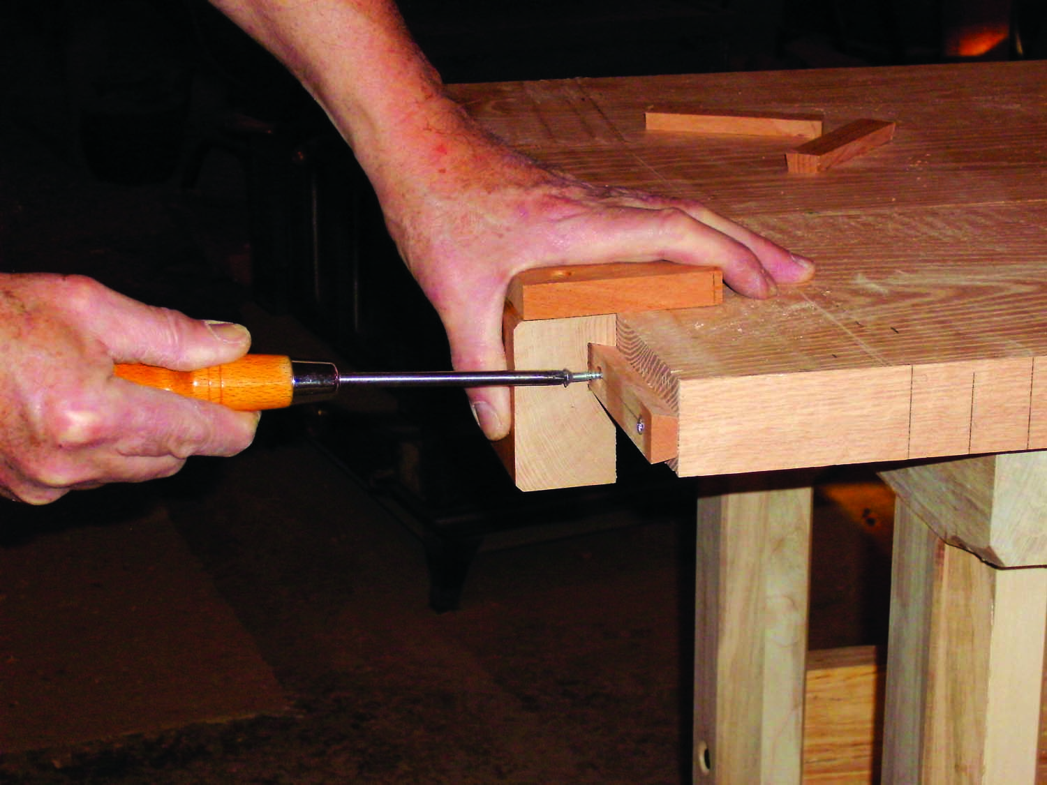
Photo 15. Fasten dovetailed keys to both ends of the top for mounting the end caps. Make a jig using an offcut from one of the end caps to position each key.
Cut the blanks into 4″-to-5″ long keys and use a jig to screw them to the bench top, spaced about 1″ apart (Photo 15). The jig is simply a 2″ wide offcut from one of the end beams with a fence fastened on top. Slide a key into the jig and position the jig on the bench. Drill a countersunk pilot hole through one end of the key and into the end of the bench. Install a screw. Repeat the process on the other end of the key. Then remove the jig. Space the keys about an inch apart, starting at the front of the bench top.
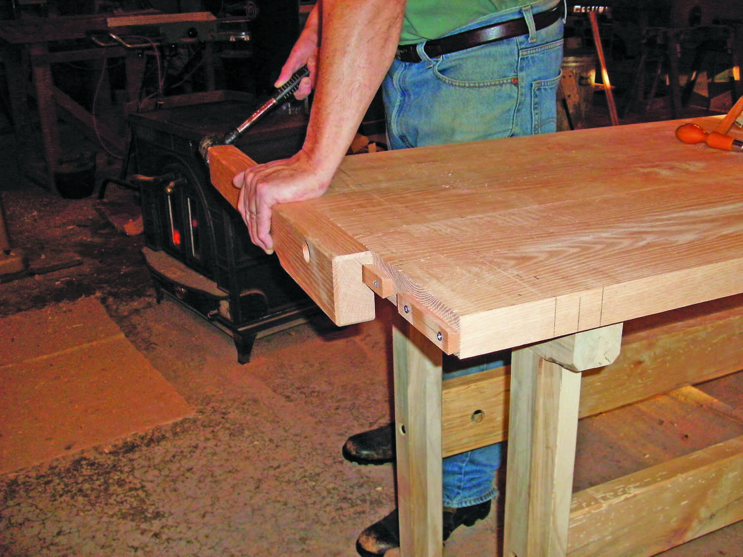
Photo 16. Slide each end cap onto the keys, flush with the front of the bench top. Then secure it with a countersunk bolt.
Rub paraffin in the end caps’ dovetailed grooves. Then drive each one onto the keys and into position flush with the front of the bench top (Photo 16). Drill a pilot hole and install a lag bolt. This bolt locks the end cap flush with the front of the top while leaving the top’s remaining width free to expand and contract. Remove the bolt and the end caps can be tapped off with a dead blow mallet. Complete the installation by trimming the back end of each end cap flush with the back of the top.
Build the Vise
The double screw vise on this bench (Fig. E) was commonly used in the 18th and 19th centuries by both English and Colonial American cabinetmakers. The wide surface of its thick front jaw, combined with the two widely spaced wooden bench screws makes it easy to clamp up and secure work of almost any size or shape.
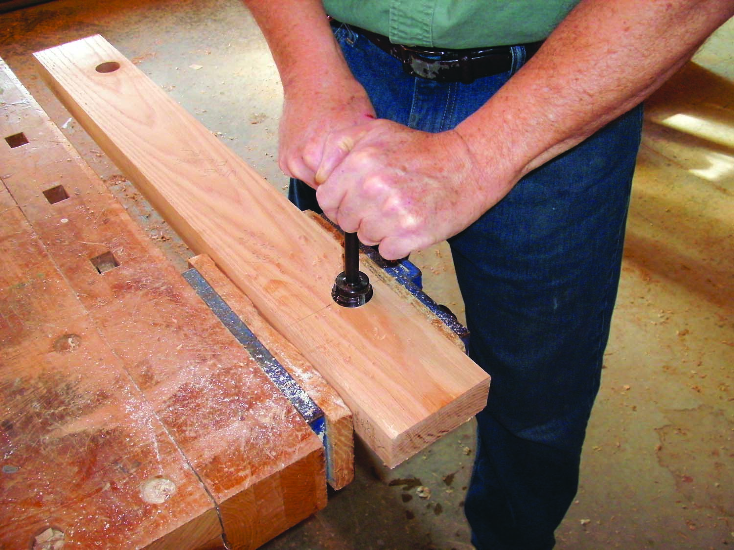
Photo 17. Drill and tap a pair of holes for the wooden screws in vise’s the fixed jaw. To thread each hole, turn the tap about 180° and then back it off to clear the waste. Then go again.
The rear (fixed) jaw of the vise (J) is simply a 4-1/2″ wide board with two threaded holes that’s glued to the bench top, flush with the front edge. Hard maple is an excellent choice for components that will be threaded. After milling the fixed jaw to final dimensions, lay out the hole locations (Fig. E) and drill the 1-3/8″ dia. holes. Then use a 1-1/2″ tap to thread the holes (Photo 17). Leave a small gap between the end cap and the rear jaw when you glue the jaw to the bench top (Photo 18).
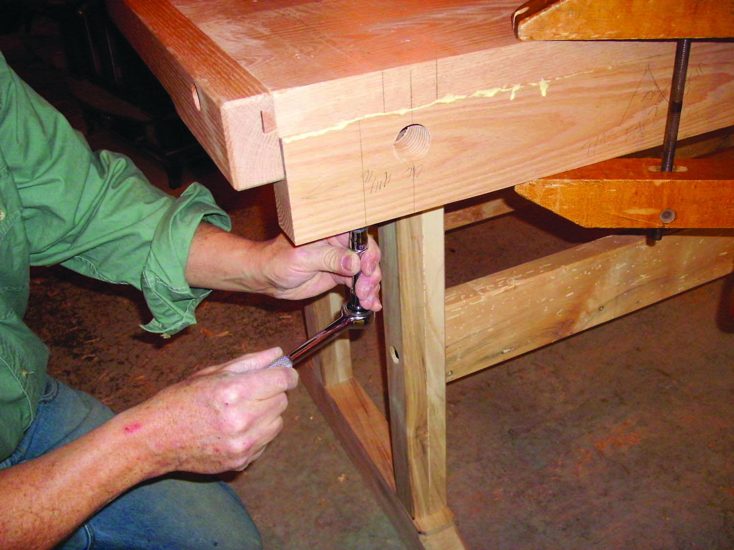
Photo 18. Fasten the fixed jaw flush with the front of the bench. This automatically centers the threaded holes on the overall width of these two parts.
The width of the vise’s front (adjustable) jaw (K) matches the overall width of the fixed jaw and bench top. Mark the best edge of the adjustable jaw so that it will face up when the jaw is installed. Then locate and drill a pair of 2″ dia. holes that are concentric with the threaded holes in the fixed jaw/bench top (Photo 19).
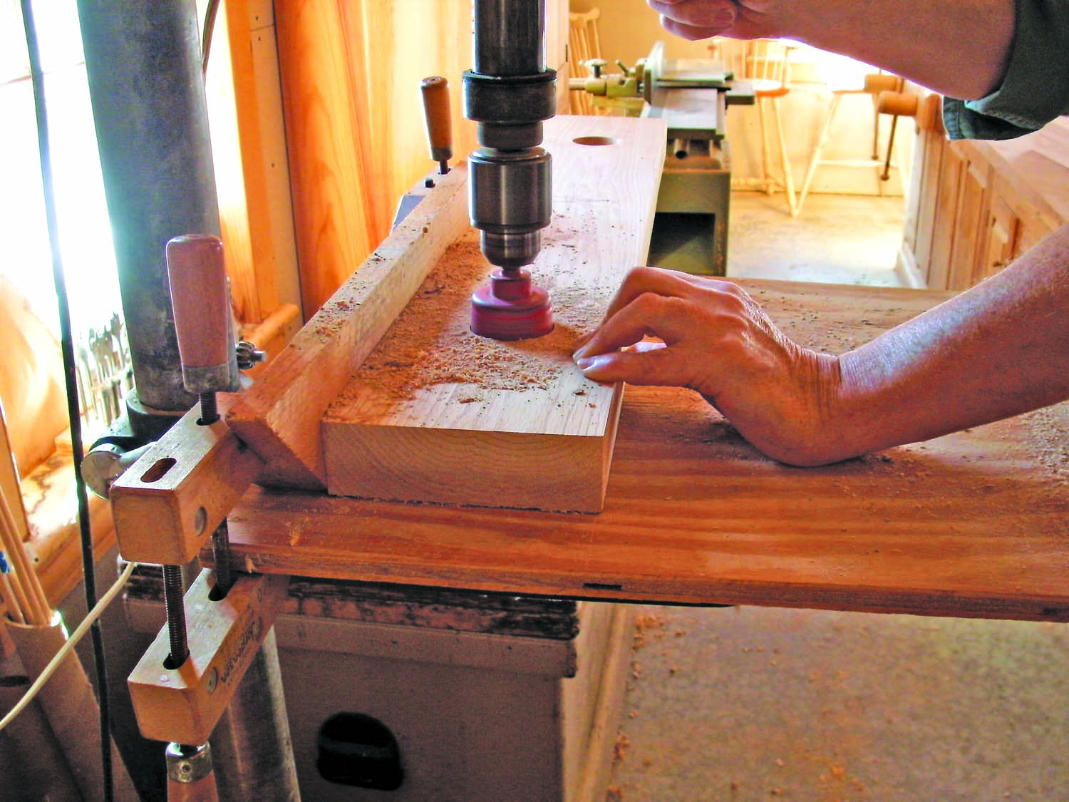
Photo 19. Drill a pair of larger holes in the vise’s adjustable jaw to house the wooden screws. These holes align with the threaded holes in the fixed jaw.
Turn Wooden Screws
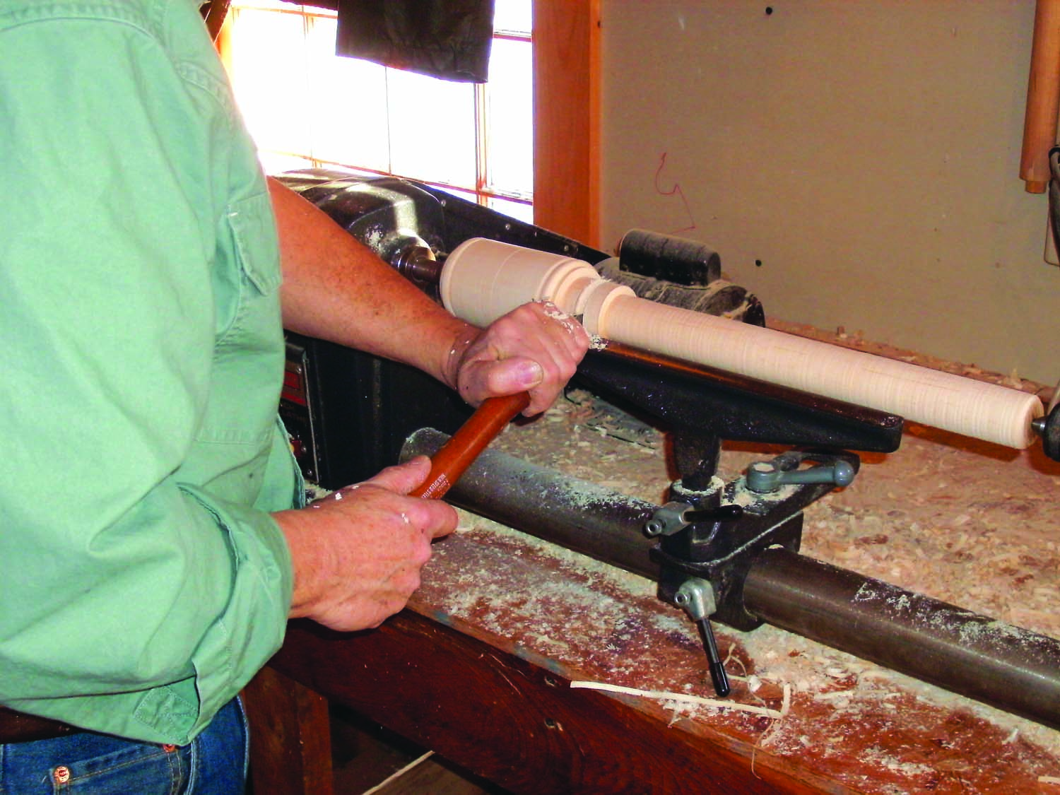
Photo 20. Turn the wooden screws. Finish by cutting a groove for the garter in the collar. The garter locks the screw in the vise’s adjustable jaw, but allows it to revolve freely.
Make the screws (L) from 21″ long maple blanks turned to 3″ dia. cylinders (Photo 20; Fig. F). Lay out and turn the head, its decorative details and the 2″ dia. x 1-1/2″ collar. Next, turn the shaft down to 1-15/32″ dia. Then finish by cutting a 1/4″ deep groove in the collar for the garter.
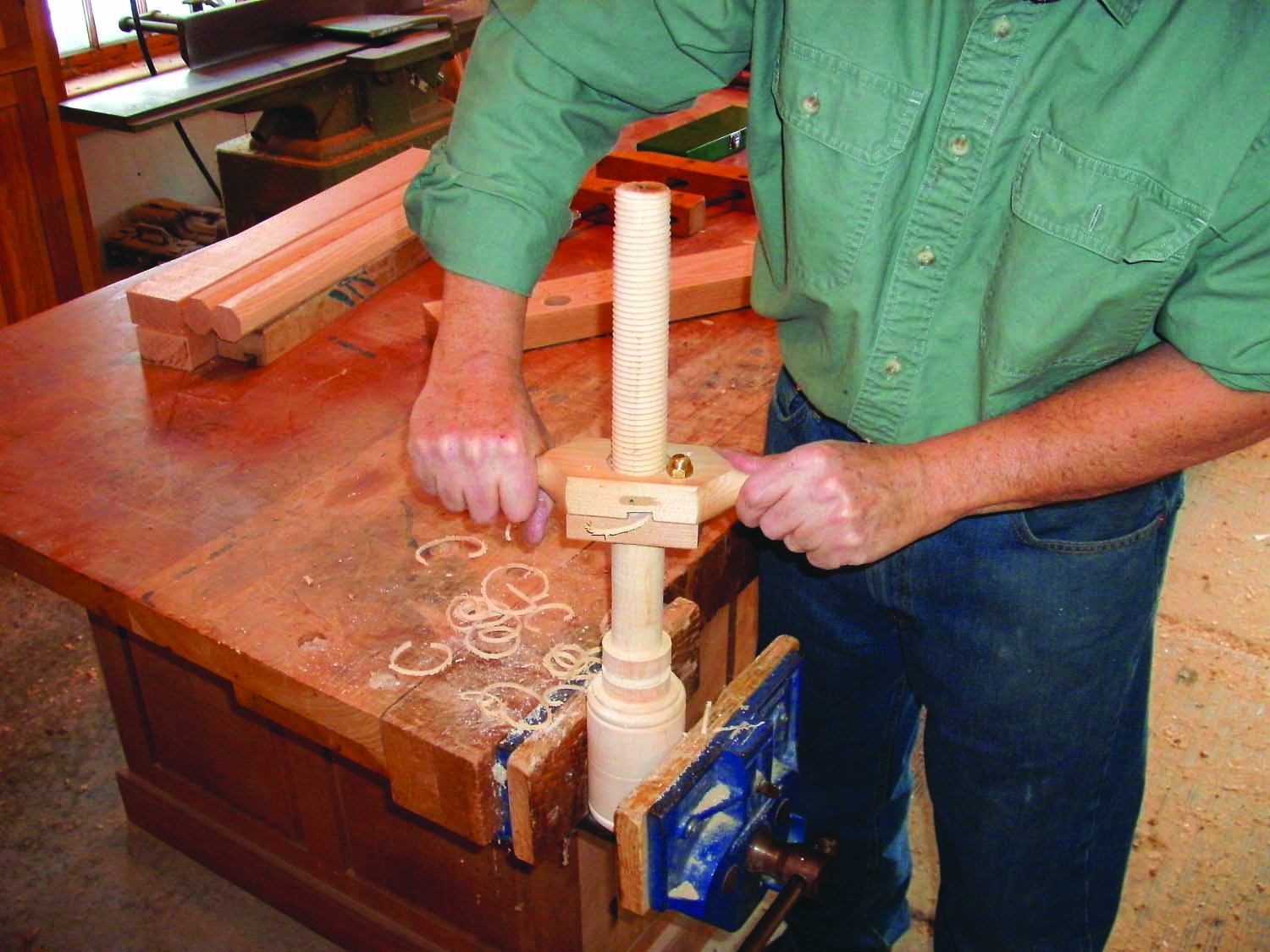
Photo 21. Use a screw box to thread the shaft of each wooden screw all the way to the collar. As before, alternate between threading and backing off to keep the thread box from binding.
Clamp the turned screw in a vise (the one on your other workbench) and use a 1-1/2″ thread box to cut threads into the shaft (Photo 21).
Use a V-block and a drill press with a fence to drill a centered 7/8″ dia. hole in the head of each screw for the handle (M). Turn the handles from 1-1/2″ x 1-1/2″ x 18″ long maple blanks. Turn the shaft of each handle to 3/4″ dia., with a 1-1/4″ dia. knob on each end. On one end, next to the knob, turn the shaft down to create a 9/16″ dia. tenon. Then remove the handle from the lathe and cut off the knob. Clamp the loose knob in a hand screw and drill a 9/16″ dia. stopped hole for the tenon. Slide the shaft of the handle through the hole in the head of the screw and then glue the loose knob onto the tenon.
Final Assembly and Mounting
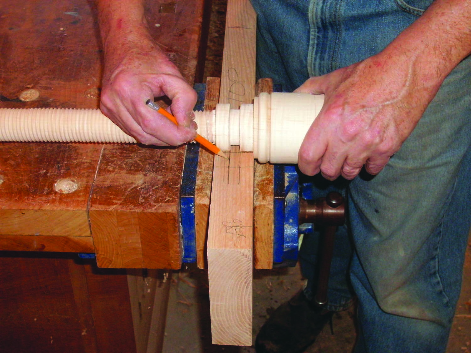
Photo 22. Mark the garter mortises on the bottom of the adjustable jaw. Butt a screw against the jaw above each hole drilled through it. Then transfer the location of both garter groove shoulders.
Turn the adjustable jaw upside-down to locate the mortises for the garters that lock the screws in the jaw (Photo 22). These 3/8″ x 2-3/4″ mortises are centered across the jaw’s width and also on the axis of each of the holes drilled to house the bench screws. Dedicate one screw to each hole, as there may be slight variations in the garter groove locations on the two screws. Draw the marks; then chop the mortises.
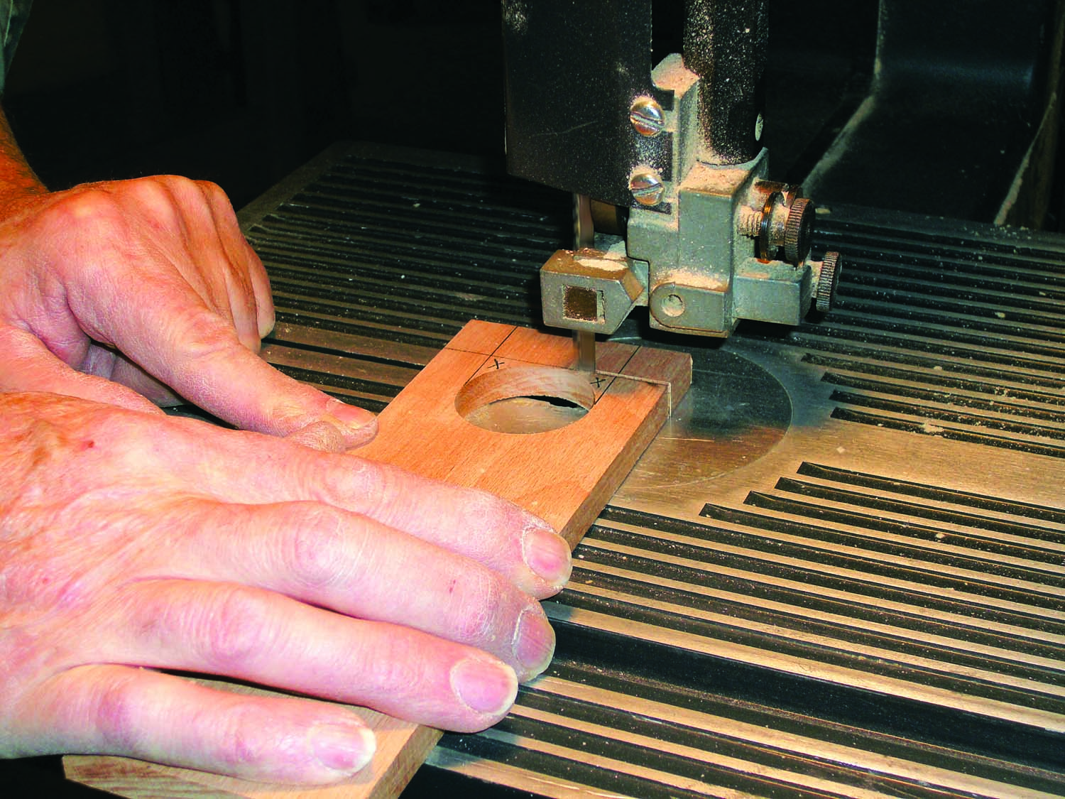
Photo 23. Cut a garter to lock each wooden screw in the vise’s adjustable jaw. First drill a hole. Then shorten the end and trim the waste to create a U-shaped cutout.
Make the garters (N). Drill a 1-1/2″ dia. hole through a 3/8″ x 2-3/4″ x 6″ blank, about 2″ from one end. Then cut off the end to create a “U” shape (Photo 23). Dry fit the screws and garters to make sure the garters allow the screws to turn smoothly.
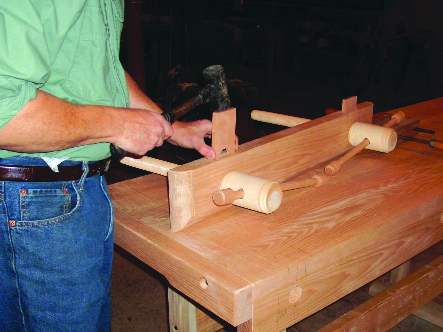
Photo 24. Tap a garter into each mortise to capture each screw. Turn the screw until the garter and the garter groove work in and operate smoothly.
To assemble the vise, set the front jaw upside-down on the bench. Slide each screw into its collar hole until its head seats against the face of the jaw. Then use a dead blow mallet to drive the garter into its mortise (Photo 24). Align the screw threads with the threads cut into the rear jaw and turn the screw handles until the vise closes up (Photo 25).
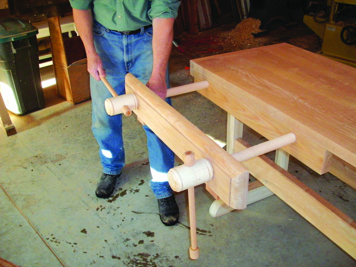
Photo 25. Install the adjustable jaw by threading the screws into the fixed jaw. Turn each screw separately until they’re both engaged. Then turn them together to close the jaw.
Bio
Steve Bunn owns and operates a cabinet shop in Bowdoinham, Maine, where he specializes in crafting Windsor chairs. Steve was juried into Early American Life magazine’s 2012 Directory of Traditional Craftsmen. See more of Steve’s work at stevenbunn.com.
Here are some supplies and tools we find essential in our everyday work around the shop. We may receive a commission from sales referred by our links; however, we have carefully selected these products for their usefulness and quality.