We may receive a commission when you use our affiliate links. However, this does not impact our recommendations.
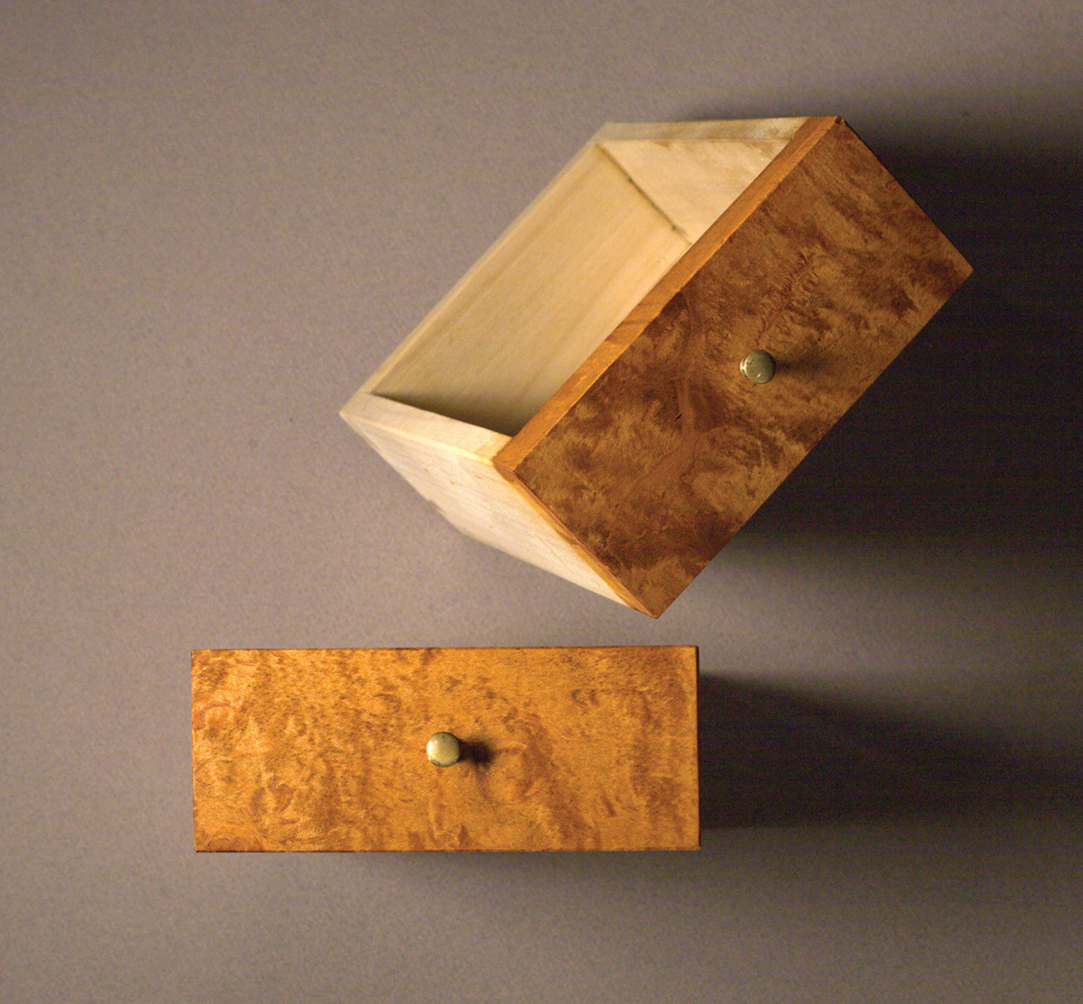
Choose one. Which view of these two small drawers gives a better sense of the space?
Isometric views help keep your designs grounded.
The kite leapt into the wind and I frantically uncoiled string that burned and chafed my hands and fingers. The thin wooden crossbeams bent almost to the breaking point again and again as the wind buffeted the kite, until finally it soared to a height where the breezes were perfect. Up in that zone of sweet steady air, just a twitch on the line made the kite dance and dive. I lost track of time until finally the light failed – and with it one perfect day from my boyhood.
Design can be a lot like flying a kite. All sorts of things can make it go haywire: too much wind; not enough wind; broken string; trees and power lines. Yet when you slip into that creative zone, it can be one of the most satisfying parts of the craft.
There are no magic formulas or equations that can make your ideas fly, but there are some techniques that can help. Among them is to learn to render your designs in an isometric drawing.
The isometric drawing is unique because it helps your eye visualize an idea in space. While not a true perspective image that connects lines back to a distant focal point, it still helps to form a valuable image to push your design forward to completion. The beauty of an isometric view is that it also keeps proportions intact from earlier two-dimensional front or side view drawings, and helps you cross an important bridge where you can judge whether the design is unified.
I’ll be clear about this: The isometric, or “iso,” drawing is not the first arrow I reach for in my design quiver. Long before I take that step, I use quick rough sketches to get a general shape of the idea (I wrote about that in the December 2015 issue, #222). From there I move to simple two-dimensional front and side drawings that do much of the heavy lifting to flesh out a design.
Front- and side-view drawings help to organize a design both vertically and horizontally, and begin the process of visualization. These two-dimensional drawings focus on proportions and how each part fits into the whole.
Yet there is only so far you can take a design with two-dimensional views. We don’t live with objects in two dimensions, and how we relate to them in space can only be seen in three. Thus an iso view can give us that layer of depth to make confident design decisions.
Magic of the Penciled Line
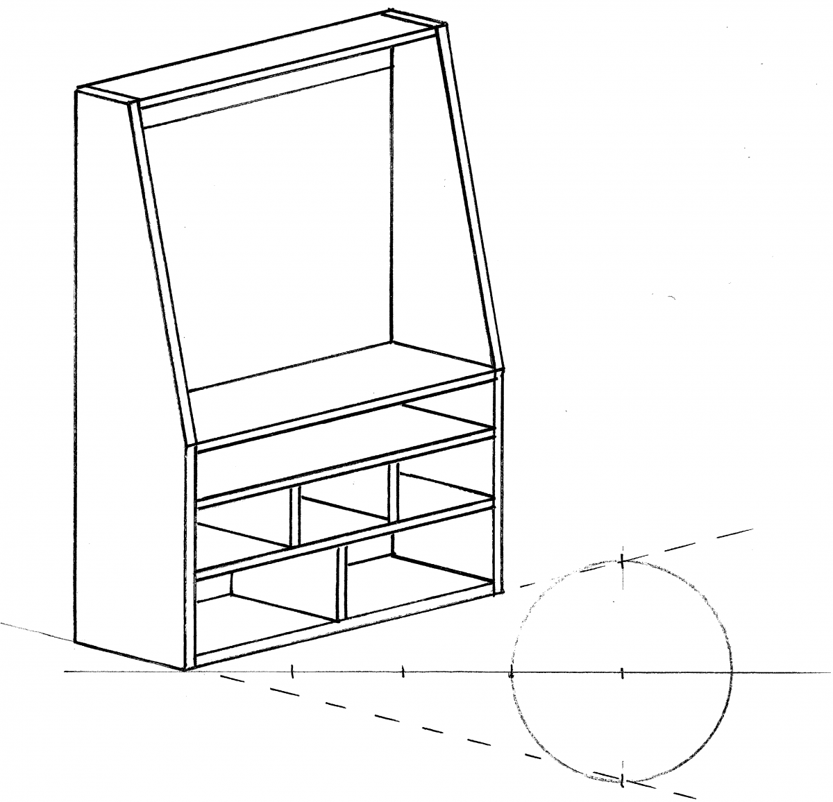
In space. With this isometric drawing, we are on the final stretch run in the design process; we see it occupy space.
You might already use digital drawing programs that can generate perspective views with the click of a mouse. Many of these can be a valuable design tool and I would never discourage their use.
But I do know from experience that there are tactile connections formed in the inner eye by walking through this simple process with a pencil, compass and straightedge. Don’t shortchange this development of your eye even if you already use or plan on using a digital drawing program. There are some powerful links you can forge in your brain that only come off the end of your pencil.
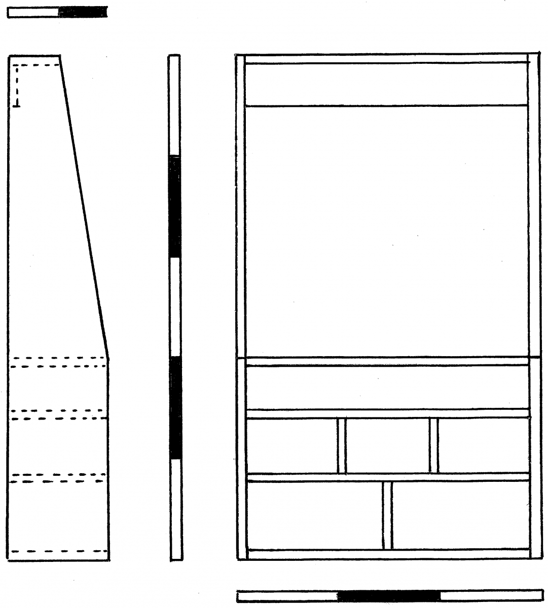
A look at proportions. Simple front and side views solidify our rough sketches and begin to refine proportions.
I mentioned earlier that this method does not produce true perspective where the lines project back to an imaginary vanishing point. That’s useful in architectural drawings of large objects such as buildings, but not as critical in smaller objects such as furniture. We can still render an image that gives us a sense of depth without the added complications of a vanishing point. It’s not necessary for our purposes.
When to Use an Iso Drawing
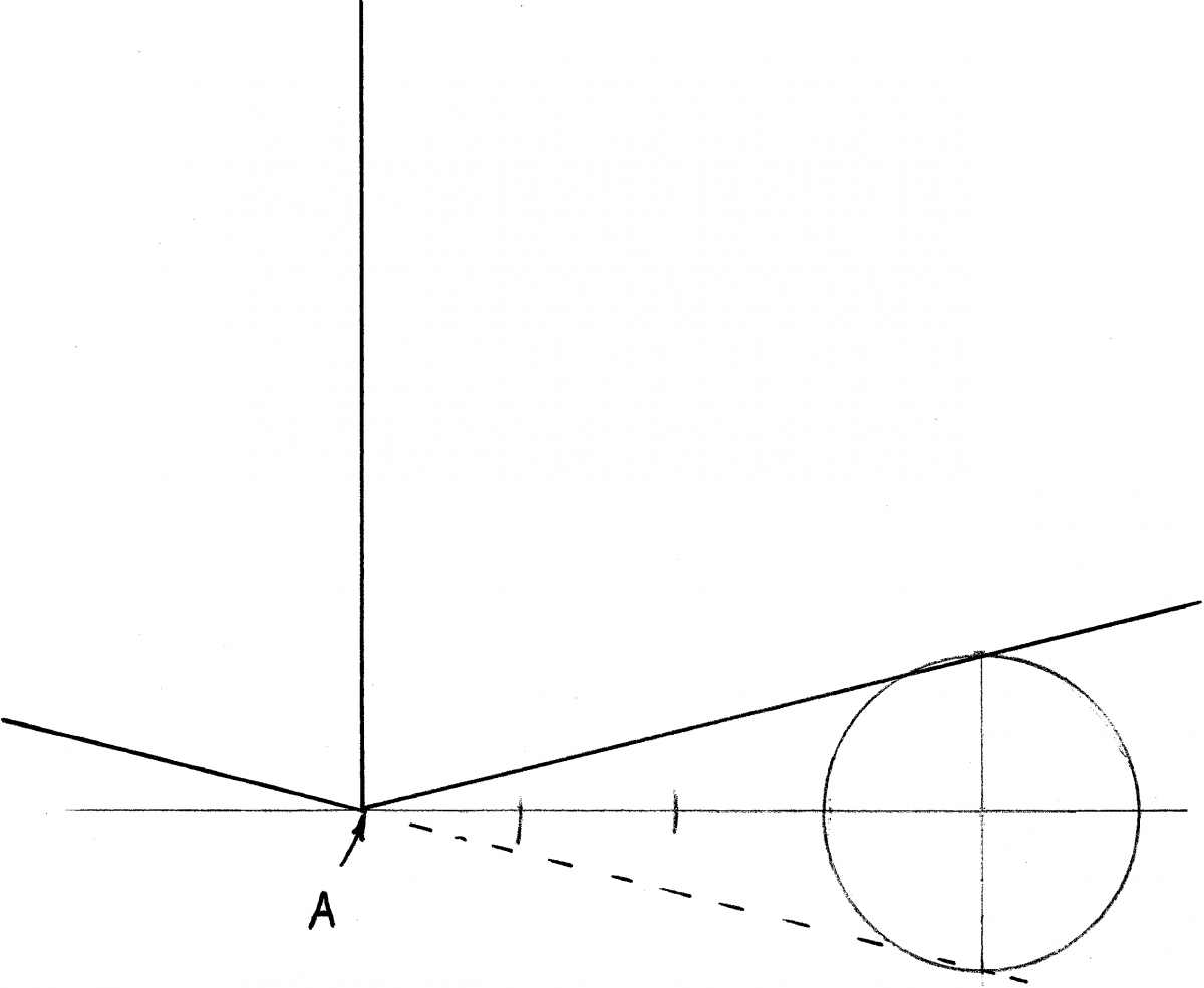
Compass power. There’s no fancy equipment or software needed. Just step out four steps from the spring point (A) and scribe a circle.
Iso drawings have little practical value when it comes to actually executing a build. Instead, their role is to refine an idea and bring it to maturity. It’s usually one of the final drawing steps before building a mock-up or scaling up a set of full-size drawings. The iso acts a marker to confirm whether we are on the right path or need to back up and restart. Better to correct our direction with a small-scale iso, then proceed with a mock-up or full-scale drawing that’s at least in the ballpark.
Pull Out Your Drawing Kit
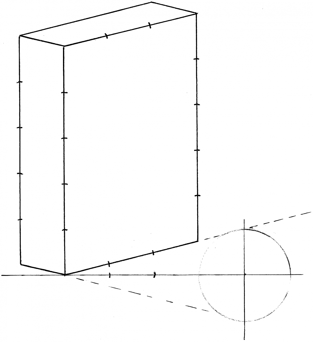
3D consideration. With baselines established we can use our simple proportions to draw a framework to flesh out our design in three dimensions.
Assuming we already have a front and side view completed, now it’s time to see them in perspective. Those front and side drawings are organized around simple proportions that we will transfer to our iso drawing. The basic shape underlying a façade (front view) drawing is often a rectangle governed by a simple ratio.
In our example, the rectangle underlying this tool rack is three parts wide by five parts high, while the side view is one part deep by five parts high. In traditional design, the common part shared in these ratios is called the “module” from which all the proportions are linked.
Take a compass and set it to the module and we are ready to transfer it to our iso. Begin the drawing by penciling in a horizontal line then a vertical line touching it. The point (A) where these two meet is the corner from where our perspective lines spring.
Using the compass still set at the module, step out four times in one direction from our spring point and anchor the point of the compass in the fourth mark. Leave the compass at the same setting and swing a reference circle.
Next, extend a line from the north pole of the circle back to and through the spring point. Then draw a second line that extends from the south pole back through our spring point.
These two lines now extend up at an angle from the spring point and become the baselines that connect both front and side views.
Now use the module on the compass to transfer the ratio of the governing rectangle from the façade view onto this new baseline and vertical, three parts over on the baseline and five parts up on the vertical. Do the same with the ratio from our side view and establish a framework in perspective that you can render the details from both your front and side views, always keeping the proportions intact.
Confirm or Deny
Once you have drawn your idea, it might encourage you that you are on the right track – or you may see that your kite is snagged hopelessly in a tree. Both outcomes can be successful if you heed what your eye is telling you and listen to your instincts. .
Here are some supplies and tools we find essential in our everyday work around the shop. We may receive a commission from sales referred by our links; however, we have carefully selected these products for their usefulness and quality.