We may receive a commission when you use our affiliate links. However, this does not impact our recommendations.
![]()
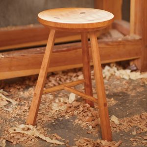
Sit up straight. Or lean back and relax. This Gustav Stickley Morris chair is an icon of American furniture design with exposed joinery and solid quartersawn white oak.
Reproduce an Arts & Crafts classic and reward yourself with the ultimate easy chair.
In Gustav Stickley’s book Craftsman Homes, there is a picture of this chair with the following caption: “A big deep chair that means comfort to a tired man when he comes home after the day’s work.” First produced around 1906, this chair is an icon of Stickley’s furniture and his philosophy.
Visually, this chair invites you to sit down and relax – a result of the sloping arms and side rails, the warmth and color of the quartersawn white oak and the upholstered seat and back. Few people who see this chair can resist the desire to sit in it. And few who sit in it can rise without regret.
Other manufacturers who knocked off Stickley’s work cut corners and simplified his designs, and many woodworkers look for a way to make a chair like this with simpler joinery. Without the joinery it isn’t a chair like this; it’s something less. There is a reward for doing it right; in this case, the reward for the effort is the chair itself.
Fools Rush In
As I prepare to build, I like to break a project down into its component parts. Each side of the base of this chair is a subassembly of two legs connected with rails. These are joined with rails front and back and are capped with the distinctive bent arms. The back of the chair is a separate unit that pivots and adjusts with a simple mechanism.
One obvious challenge is making the arm, but that is simpler than it seems. The rails and slats below the arms seem simple, but the slope that makes the chair appealing complicates these parts.
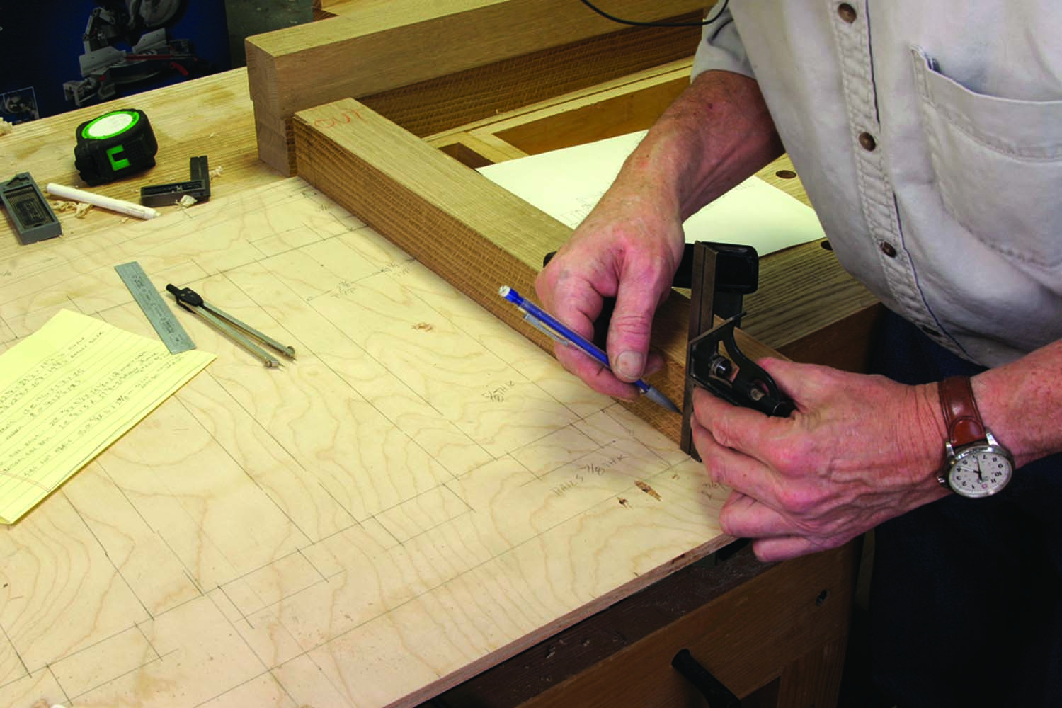
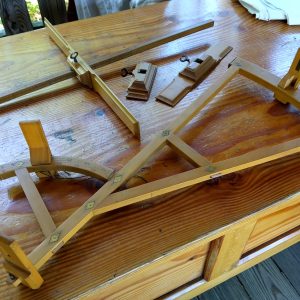
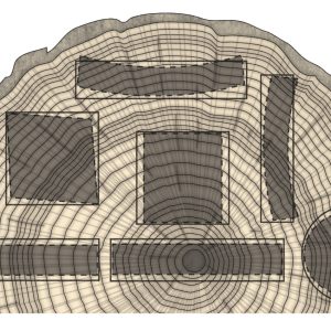
Measure once. A full-scale drawing provides a reference for most parts of the project. It saves time, and prevents measurement and layout errors.
The first step in making this chair is to draw a full-size layout of the side assembly. It’s a good exercise in understanding how it all goes together, and it’s an indispensable reference for the actual sizes and angles of the component parts.
The top edge of the top side rail is angled, rising from a height of 15⁄16″ at the back leg to the full width of 31⁄2″ at a point 3⁄4″ behind the front leg. The bottom edge of this rail is parallel to the floor, and perpendicular to the legs. The bottom rail is a constant width, but it meets the legs at a slight angle; the back is 3⁄4″ lower than the front.
That slope makes the through-tenons on each end of the lower rail a little trickier, but the real complication is that each of the vertical slats is a different length. After drawing the full-size view, I switched gears and made the legs, which gave me something useful to do as I pondered the implications of the angled ends of the slats. 


 Trees Don’t Grow Like That
Quartersawn figure on all four sides of the legs was a feature of original versions of this chair, and I used the same method used in Stickley’s Craftsman Workshops. Three pieces of 13⁄16″-thick material were laminated into a stack. After letting the glue cure overnight, I dressed the surfaces on the jointer.
Then I glued a 1⁄8″-thick piece of quartersawn wood to the side edges of the leg laminations. These thick veneers were sliced on the band saw and cover the unattractive side grain (as well as the joint lines) on the legs. After an overnight wait for the glue to cure, the legs were dressed down to 23⁄8″ square.
The edges of the legs are beveled, with the bevel ending at the glue line between the solid and veneered edges. I placed the finished legs on the full-size layout to locate the tenons at the tops, and the mortises, marking the locations directly on the legs from the drawing.
I made the 5⁄8″-wide through-mortises with a hollow-chisel mortiser, working from both sides with a 1⁄2″ chisel and bit. That size bit takes less effort to plunge into the work, and I centered the mortises by cutting one side of the joint, then flipped the workpiece so the opposite side was against the machine’s fence.
I also cut the angle on the back legs, and the 11⁄2″ square tenons on the tops of all the legs before proceeding. The tenons on the ends of the side rails were cut, and I dry-fit test assemblies of the sides. I located the taper for the top rail from the test assembly and after cutting it on the band saw, I put each side assembly on top of my drawing.
“… As we grow older and begin to stand on our own feet and to cherish our own standards of life and of work and therefore of art, we show an unmistakable tendency to get away from shams and to demand the real thing.”
— Gustav Stickley (1858-1942)
Use This to Measure That

Keep your head straight. A tapered piece of scrap below the workpiece keeps the mortises oriented vertically.
I marked the locations of the vertical slats on the top and bottom rails, along with the mortises for the slats. Then, with a lumber crayon I marked each mortise with a number. I put each slat in position, numbered each with the crayon and marked the shoulder locations directly from the rails.
Each vertical slat is a bit longer than its neighbor, and if the slats move sideways along the rail the length will change. A slat that is slightly long or short can be moved for appearance sake, but more than a slight adjustment will show as inconsistent gaps between the slats. Moving one slat laterally will also affect the fit of an adjacent slat.
Many Mortises
The mortises in the rails are centered and I made them with a 3⁄8″-wide chisel in the mortising machine. I saved the offcuts from the top rails and temporarily reattached them with tape to keep the mortises vertical. I cut a long wedge to hold the bottom rail at the correct angle to keep those mortises vertical.

Don’t throw that away. The offcuts from tapering the upper rails are taped back in place to keep the clamps from sliding during assembly.
I cut all of the tenon shoulders by hand. That gave me more control over the angles and a better cut edge than cutting them by machine. I cut the tenon cheeks on the band saw, and adjusted the fit with a shoulder plane and a float. When the slats were fit to the two rails I made a trial run of that subassembly with the legs.
I made a few minor adjustments to get a good fit everywhere. Before gluing the slats in position, I smoothed all the edges of the rails and slats with my plane and rounded all the edges slightly.
Through & Through
The through-tenons on the bottom rails give the chair frame strength – if they fit well. They also need to look good from the outside. Good looks are a given if the joints fit, and the key to it all is planning and patience.
The mortise walls need to be straight and consistent, so I spent some time with a float to even out rough areas left from the hollow chisel. I also made sure that the ends were square and the walls of the mortises were perpendicular to the faces of the legs. With a chisel, I cut a small bevel on the inside edge of each mortise to ease starting the tenons.
To determine the exact tenon width, I held the end of a rail against the long edge of a mortise, and made a pencil mark to transfer the width of the mortise. I then took my marking gauge and set it halfway between the pencil mark and the opposite face of the rail. I made a test mark from each side and held the end of the rail to the mortise to check that the widths matched.
When I was satisfied that I had the correct size for the tenons, I marked the edges and ends of the rails with my gauge. I clamped both rails together and marked the shoulder locations at the same time to be sure they matched. The shoulder cuts are only 1⁄8″ deep, and I cut these by hand at a bench hook using my backsaw.
At the band saw, I set the fence so that a tooth angled toward the fence was just outside the marked line. I held the rails against the fence and cut the wide cheeks back to almost the shoulder line. I measured the tenon and the mortise with dial calipers to compare the sizes. My goal was a fence setting that left the tenon barely thicker than the mortise. This prevents a sloppy tenon, but it means that some tweaking must be done to get a good fit.
Before fitting, I cut a chamfer on the end of each tenon. This makes it easy to insert the tenon for a test fit, and it keeps the end of the tenon from doing any damage to the outer edges of the mortise when it comes through.
Fitting is a matter of removing a small amount of material at a time and seeing how far the tenon will go into the mortise. I generally start with a shoulder plane, being careful not to introduce a taper in the tenon. As I get closer, I switch to a float. The float is easier to control and leaves a nicer surface.
Hatch marks made with a pencil on the tenon indicate high spots that keep the joint from going home. The graphite smears at the sticking points, and I used the float to take off the smeared spots. I don’t use a mallet to try to drive the tenon in; if that much force is necessary, something is likely to break.
Hand pressure is enough, and when the tenon can be inserted about two-thirds of the way, I can look from the outside to see if there are any problem areas. The first assembly is the hardest. I usually take joints apart and put them back together several times as I’m working to tune the fit at the shoulder and to make trial runs before making a final assembly with glue and clamps.

Only if you have to. Because the lower end of the vertical slats are angled, they only fit in one place. They can be adjusted with a tap or two.
When I was happy with the fit, I marked with a pencil where the outside of the leg lands on the exposed tenon. I cut the tenon 1⁄4″ beyond that line, then chamfered the end of the tenon back to the line with a block plane, rasp and finally sandpaper. Leaving the line ensures that the visible intersection of the tenon and the leg looks tight.
Bring on the Glue
Assembly of the base of the chair is done in stages; first the vertical slats are glued between the top and bottom rails for each side. I used liquid hide glue to gain some extra open time, and held the angled offcut from the top rail in place with painter’s tape to keep the clamps from sliding. I used a block of soft wood and a mallet to fine-tune the lateral position of the slats.

Control the glue goo. Start the through-tenon in the mortise before brushing on the glue to keep the end of the tenon clean.
I let that dry in the clamps overnight, and glued the legs to each end of the rail assemblies the following morning. To keep glue from going everywhere around the through-mortises, I started the tenons in the holes, then brushed glue on the cheeks before assembling and clamping the joints.
After letting the rail-to-leg joints dry overnight, I marked and drilled a 5⁄8″-diameter hole 13⁄8″ deep on the inside of each of the back legs. I then connected the two side assemblies with the front and back rails. This assembly was also left in the clamps overnight.

Stress management. With the sides glued into units, the last stage of the base assembly is a simple matter.
The arms complete the side assemblies, and are cut from a piece of 15⁄16″ x 53⁄8″ stock. I started with a piece several inches longer than the finished length to get the angle of the bend and the tenon locations right first. Before making the arm, I made sure that the top edges of the top rails were in line with the shoulders on the tops of the legs.
I placed the stock of an adjustable bevel on the shoulder of the front leg, and set the blade to the slope of the rail. I transferred this angle to the edge of the arm. The bend is actually a tapered slice cut from the top of the leg, then glued to the bottom edge.
After making the cut on the band saw, I glued the wedge to the bottom of the arm. This leaves the sawn edges exposed on the top and bottom surfaces of the arm, and the previously surfaced faces glued together. I removed the saw marks with my plane.


Can’t miss. Balance the arm on the base assembly and mark the location of both the front and back tenons without moving the arm.

Nothing to see here. The glue line should disappear because the grain and color are the same in both pieces.

Smooth it over. Planing out the band saw marks leaves a smooth surface on the top and bottom of the arm.

Get to the bottom. The wedge is glued to the underside of the arm, smooth face to smooth face.

A little off the top. An angled wedge sliced off the end of the arm forms the bend.
Location, Location, Location
The through-mortises on the arms are the most visible joints in the chair, and there aren’t any magic tricks or shortcuts to the process. The mortises need to be just right, and in just the right place. I flipped the assembled base of the chair on its side so I could locate the joints in each arm directly from the tenons.
I placed the arm on top of the tenons in the legs, lining up the angle in the arm with the angle in the top rail behind the front leg. With a square I carried the edges of the tenon around both the top and bottom face of the arm. The procedure was roughly the same for the back tenon, except that I used an adjustable bevel to carry the lines over the edges.

Follow around. An adjustable bevel transfers the layout lines for the angled mortise from the top of the arm to the bottom.

On the up and up. A wedge below the arm provides the proper tilt to keep the holes vertical.
When the chair is finished, the arm extends 1⁄4″ past the leg on the inside. I measured from the side of the leg to the cheek of the tenon, added the 1⁄4″ and marked the side of the mortise on the upper and lower faces of the arm. I then measured the tenon width and marked that distance on the face of the arm for the second edge of the mortise.
An accurate layout is half the battle so I stepped back and double-checked my lines before cutting. I removed most of the waste inside the lines with a 3⁄4″ Forstner bit at the drill press. For the front mortises, I placed a block of wood below the arm to support the horizontal end level while drilling.
At the back of the arm, I cut a wedge from a scrap of 8/4 material to support the arm while drilling to keep the front and back edges of the mortises plumb. I used this same wedge to support the arm on the bench as I pared the mortise walls back to the layout lines.

Careful comparison. Check the size frequently with calipers as you work on the mortise, and compare it to the tenon.

Careful comparison. Check the size frequently with calipers as you work on the mortise, and compare it to the tenon.
I worked carefully and checked frequently to avoid over-cutting the mortises. It isn’t possible to check the fit of the tenons one at a time. As with the through-tenons connecting the rails and legs, I beveled the ends of the tenons and hidden edges of the mortises before fitting, and used pencil marks on the tenons to locate any high spots.

After the fit. Mark the intersection of the arm and the tenon with a pencil line and round the end of the tenon down to the edge. Stop just outside the line to maintain the fit between the two parts.
When I had a good fit, I marked the top edge of the arms on the leg tenons, then removed the arms and rounded over the exposed ends of the tenons with a block plane and rasp. Before permanently attaching the arms, I drilled a series of 5⁄8″-diameter holes on the inside back edges for the support pins.
 Back in a Week
While waiting for the glue to dry on the base assemblies, I made the curved back slats. I built a form from four layers of 3⁄4″-thick particle board cut to a 36″ radius. I cut the curve on the first layer at the band saw, then smoothed the edge. The remaining edges were cut oversize, and each layer was added to the stack, then trimmed to the previous layer with a flush-cutting router bit.
Each slat consists of six 1⁄8″-thick layers. I marked a triangle on the edge of the slat blanks to keep the pieces in order, and made the cuts on the band saw. With a decent saw cut, the laminations can be glued without any further smoothing. I used a 3″ paint roller to apply yellow glue, put the stacked pieces against the form and started clamping from the middle out to each end.

Work fast. Use a roller to spread glue on one side only of the laminations for the back. Keep the pieces in order and the edges will match.
I used a piece of 1⁄4″-thick Plexiglas between the wood and the clamps to spread the pressure and prevent clamp marks on the wood, and left each stack on the form overnight. When all five slats were finished, I scraped the excess glue from the edges, ran one edge over the jointer, then trimmed the slats to width on the table saw.
To lay out the tenons on the ends of the curved pieces, I prepared a straight stick with a tenon on each end. By placing this stick on the top edge of the slats, I was able to mark the tenons on the curved parts by tracing. I then carried the lines around the slats with a square and an adjustable bevel.

Around the bend. Mark the tenons all the way around the slat with a square and an adjustable bevel. Go over the lines with a knife before cutting the shoulders with a backsaw.

Stick with it. Make a pattern on scrap to lay out the tenon locations on the curved back rails. Hold the stick in place and mark both ends without moving the stick.
I made the shoulder cuts by hand after going over the layout lines with a knife. The slats stayed put on the bench hook with the convex side of the curve on top. To cut the other side, with the curve up, I put a wedge of scrap below the slat and held the slats to the bench with a clamp while I made the cuts. I cut the cheeks at the band saw.

Quick cheeks. A band saw is an efficient way to cut the tenon cheeks, or you can cut them by hand. Either way, cut a little wide and make the tenons fit with a shoulder plane or a float.
The 1⁄4″-wide, 1″-deep mortises in the back stiles are centered in the thickness of the rails, and were cut with the hollow-chisel mortiser. Before assembly, I sanded all the parts for the back, chamferred the edges of the stiles and drilled the holes at the bottom of the stiles.
When assembled, the width of the back should be about 1⁄8″ less than the distance between the arms to allow the back to adjust without interference.
What the Holes Are For
Wooden pins serve as pivots for the back, and as stops to adjust the back to any of four positions. I started with four 1″-square blocks about 8″ long and turned a 5⁄8″-diameter shaft on one half. These could also be made by gluing a dowel into a hole drilled in the end of a square block. I sanded the shafts to reduce the diameter slightly. These should go easily in and out of the holes in the arms and back legs.
After fitting the pins, I trimmed them to length. The bottom pins pass through the stiles of the back, and the round shafts are about 2″ longer than the depth of the holes in the back legs. The upper set of pins are the same depth as the holes, and the square section should be about 2″ long.
I used a block plane to chamfer the edges of the square end of the pins to an octagon shape and to round off the ends. Round wooden washers hold the back assembly away from the legs. These are 2″ in diameter, and I waited until the arms were glued to the base, and the back was assembled, to make them.

Turn then whittle. After turning one end of the pin, trim it to length then shave the sides to an octagon. The last step is to round the end to a hand-friendly dome shape.
I used a piece of scrap 2″ wide and 12″ long, and aimed for a thickness half the difference between the back and the back legs. Then I took another 1⁄32″ off the thickness before drilling the holes and cutting the outside to a circular shape. These doughnuts keep the back from rubbing on the arms, but they must be thin enough to allow the back to swing without binding.

Take it for a spin. The back of the chair pivots on the lower set of pins, and the large wooden washers keep the back centered without rubbing on the arms. The upper pins support the back in one of four positions, from upright to do not disturb.
The last pieces to be fabricated are the four corbels that support the outer halves of the arms at each leg. All four corbels are cut to the pattern from 11⁄8″-thick stock. The back corbels should be about 1⁄2″ shorter in the straight section than the front. The top of the back corbels also must be angled to match the slope at the top of the back legs below the arms.
The corbels are centered on the legs and are held to the leg with glue and a screw in a plugged hole. The screw isn’t necessary as the glue alone would be strong enough, but it makes it easier to hold the corbel in position. Without the screw, the corbels slide around as the clamps are tightened.
When the glue holding the corbels dried, the screw holes were filled with dowels. The through-tenons on the base assembly were also pinned with dowels, as well as the tenons in the top and bottom slats of the back assembly.
I make dowels from straight-grained scrap. I start with a piece about 3″ long and split blanks from the scrap with a chisel or a stout knife. I then drive the dowels through holes in a 1⁄4″-thick steel dowel plate. I whittle the ends to get them started, and knock off the corners with a chisel so there is less material to remove.
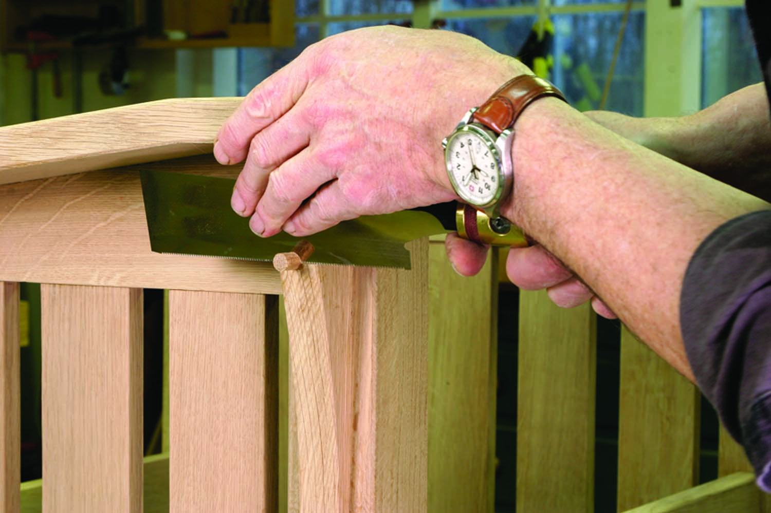
Suspenders and a belt. Dowels cover screws that hold the corbels to the legs. The through mortises on the legs are also pegged with dowels made from scraps. Trim them flush before finishing.
The dowels are coated with glue and driven into place. After the glue has dried, the pegs are trimmed flush with a saw. The saw can leave a fraction of the plug proud of the surface, so a bit of paring with a chisel was needed in a couple places.
Hard Surfaces, Soft Surfaces
As I worked, I smoothed exposed faces and edges with my planes before assembling. I also chamfered the long edges with my block plane, and I used a rasp and sandpaper to round the exposed tenons. In a few places I had some tear-out to deal with where the grain direction reversed, and I used a card scraper to smooth these troublemakers.
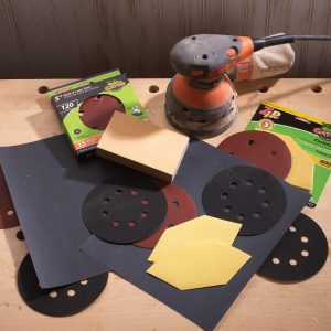
Each of these tools leaves a smooth surface, but with a slightly different texture. To get an even texture before finishing, I sanded the entire chair, first with #120-grit Abranet, then #180 grit. Sanding white oak to too fine a grit can polish the surface to a point where it won’t absorb color evenly. If scratches from sanding aren’t visible, the wood is smooth enough to dye.
I used Lockwood’s Fumed Oak (#94) aniline dye dissolved in alcohol. This dries quickly as it is brushed on and doesn’t raise the grain. I aimed for a consistent coat on all surfaces without running the dye. The color is close to that of white oak fumed with ammonia, and there is another similarity between the dye and fuming; the surface looks like you ruined it when it dries.
I rubbed the entire chair with an abrasive pad after letting the dye dry for a few hours, then brushed on a 50-50 mixture of clear and amber shellac. I diluted this about a third with alcohol. The following morning I went over the chair again with the abrasive pad, then brushed on a second coat of shellac. After letting the shellac cure for a week, I gave the chair a coat of Dark Watco Satin wax, applied with an abrasive pad then buffed with a cotton cloth.
I had a local upholstery shop make the cushions. The bottom cushion rests on 3⁄4″ x 1″ cleats screwed to the inside of the front and back rails, 11⁄4″ down from the top edge. The cushion consists of a solid-wood frame made of 2×4 material, ripped to 2″ wide.
The corners are mitered and held together with glue and screws, with 45˚ corner blocks for additional strength. Rubber webbing was stapled to the top edge of the frame. The webbing covers the entire opening, running in both directions in a basketweave.
A 1″-thick, 12″-square piece of high density foam was glued to the center of the webbing to give the cushion a crown. On top of this is a 4″-thick piece of high-density foam wrapped in Dacron. The fabric wraps over the foam and is stapled to the bottom of the wood frame.
The back cushion is a 2″-thick piece of soft foam wrapped twice in Dacron. The buttons in the back of this cushion help it to conform to the curve of the back, and loops of fabric hold the cushion in place on the back frame.

View the SketchUp Model of the Stickley Morris Chair
Upholstery Info: MorrisChairUpholstery