We may receive a commission when you use our affiliate links. However, this does not impact our recommendations.
Conquer some fun joinery challenges with this geometric Baillie Scott build.
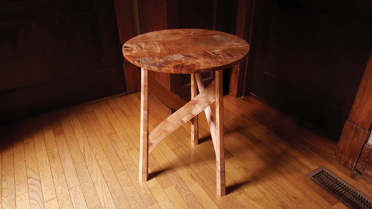
As soon as I saw Mackay Hugh Baillie Scott’s 1901 occasional table on display at the Museum of Modern Art in New York, I knew I had to make one.
Baillie Scott (1865-1945) was an architect at the forefront of the Arts & Crafts movement in England. His diminutive and elegant table is uncharacteristic of the often substantial and earthy furniture of the Arts & Crafts style.
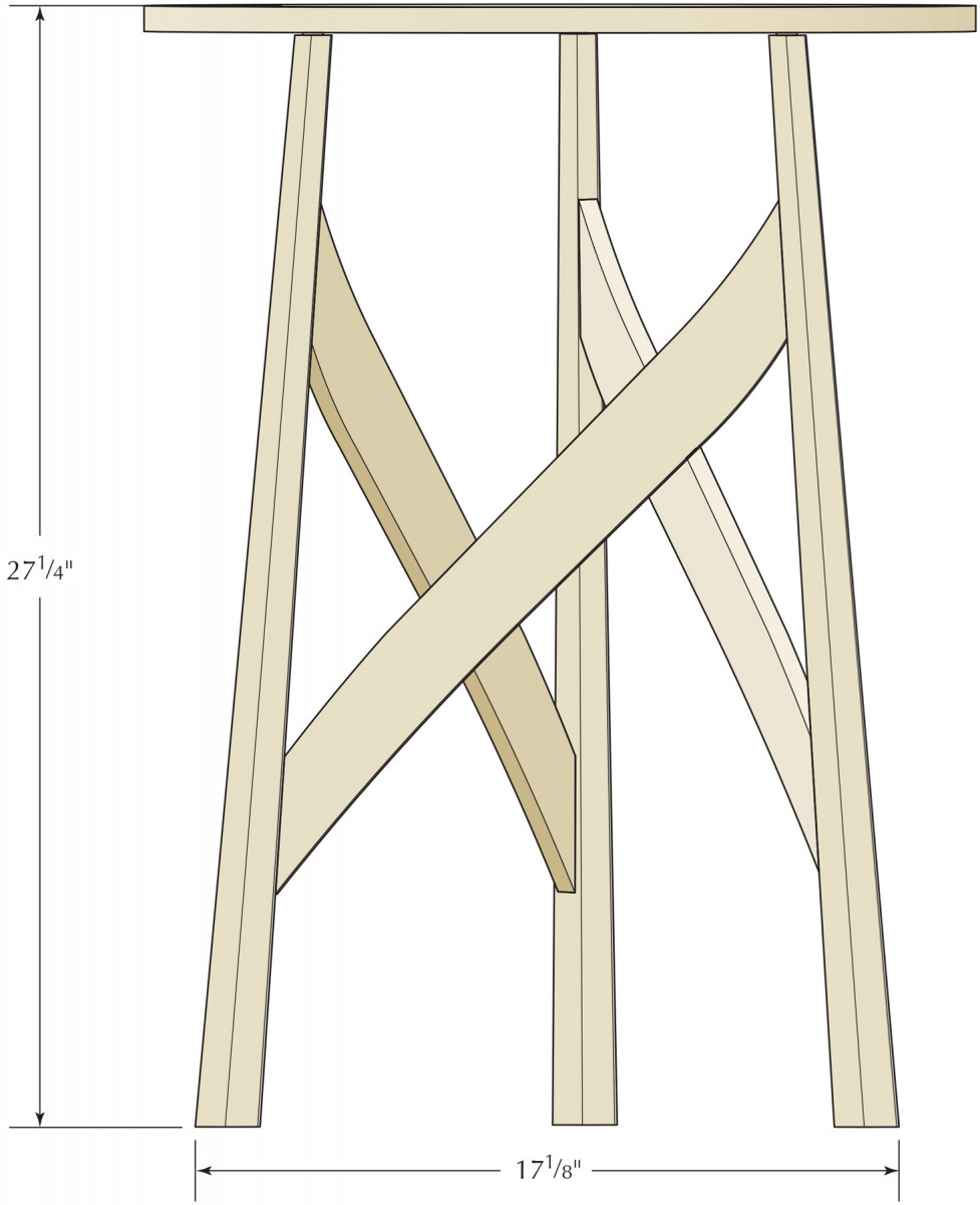
The lightness and movement of the table, which come from a play between positive and negative space, make it a true piece of sculpture that looks different from every perspective.
Plywood Layout
Though it is made from only seven parts, this little table presents several challenges. First, there is not a single right angle in sight. The three legs are splayed and joined with curved stretchers angled upward from left to right, which flow into the round top. As if all that were not challenging enough, the legs are tapered and hexagonal.
If you enjoy the problem-solving aspect of making furniture as much as I do, this project is for you. Read on to discover how to face each challenge.
The three legs are joined to the stretchers using floating tenons. The legs and top are joined with wedged through-tenons. Figuring out where the joints go is the goal of a full-size drawing.
Start with Full-size Drawings
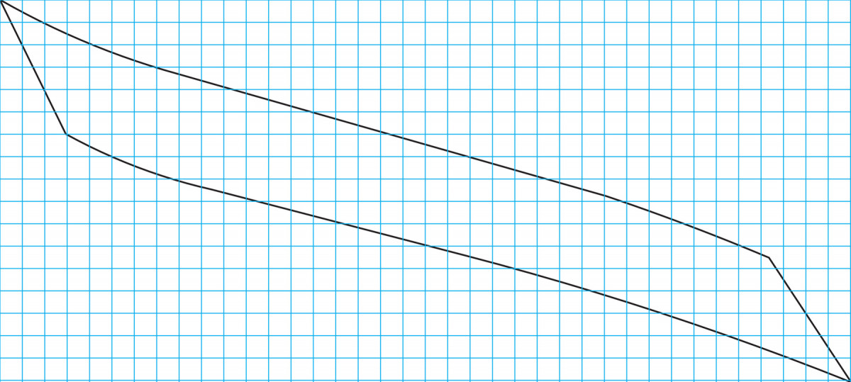
Leg Pattern 1 square = 1⁄2″
This project demands accurate drawings that you can use to define angles and locate joinery. The best way to approach this table is to create full-size drawings on a piece of plywood. On one face of the plywood, you’ll draw the plan view of the table. On the other face, you will draw the elevation. These two drawings work together to give you the all the angles and part sizes you need.
The other good thing to know off the bat is that you will not need to cut tenons at a compound angle. The three hexagonal legs offer joinery surfaces that are parallel to each other (very clever, Mr. Baillie Scott).
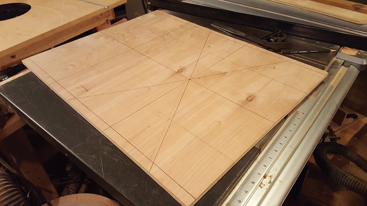
Start square. Lay out the top of the table using a piece of plywood, which will make it easy to transfer the lines to the other side of the plywood, which has the elevation drawing.
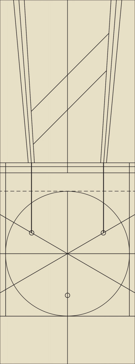
Begin by drawing the top as a 22″ x 22″ square on one face of the plywood. Establish a center point on the circular top and draw a vertical line through it. Mark one leg (we’ll call it the back leg) on this centerline that is 31⁄2” from the back edge of the top. Then draw lines out at 120° to locate the other two legs (we’ll call these the front legs). Make marks on these three lines 63⁄4” from the center. These are the locations of the mortises.
Now we’re going to pull some of the important lines to the other face of the plywood for the elevation view. Pull the locations of the two front legs to the edge of the plywood and wrap them around the edge. Flip the plywood over. Working from the edge that has your marks, measure 1″ off that edge and strike two horizontal lines to establish the tabletop, which is 5⁄8” thick, in elevation view. (The extra 1″ of space gives you room for drawing reference lines.)
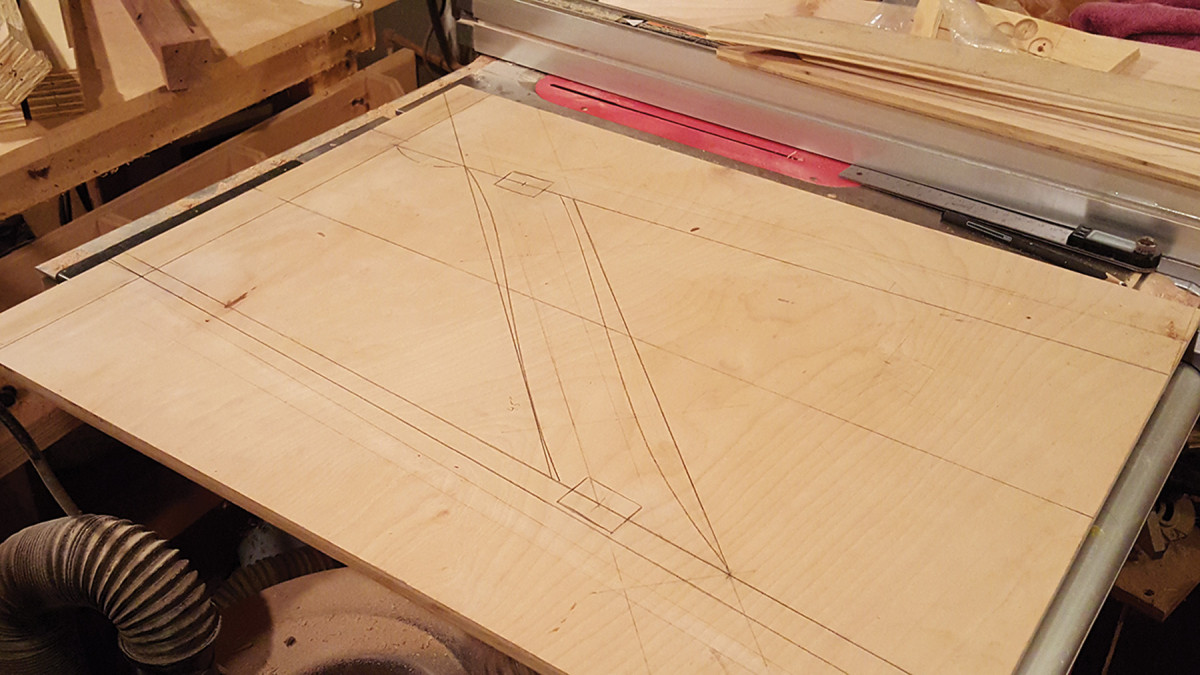
One drawing. The three stretchers and legs are identical so you need to make only one drawing for the elevation.
Draw centerlines for the two front legs at a 4.5° splay. Then draw the inner faces of the legs. The legs taper from 1″ thick at the top and end up at 13⁄4” x 2″ at the floor. In the elevation view on your plywood, the 2″ width is facing you. So the inner face of the leg should taper from 1⁄2” off your centerline at the top of the leg to 1″ off the centerline at the floor.
Stretcher joinery. Use the drawing to precisely locate joinery, in this case the loose tenons that join the stretchers and legs.
Draw the top line of the stretcher blanks pitched at 45° from parallel and intersecting the inside face of the right front leg 3″ down from the underside of the tabletop. The top line establishes the angles at which the stretchers meet the legs.
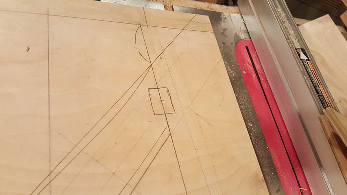
You also should draw in the bottom line of the 3 1⁄4“-wide stretcher and its serpentine edges. Use the gridded drawing to lay out the subtle curves on the stretchers.
One tricky thing is that the mortises for the legs are drilled into the underside of the top, so you need to account for the splay of the legs on your full-size drawing by scribing a perpendicular line from the edge of the plywood to where the leg’s centerline meets the line representing the underside of the top on your plywood drawing. Transfer this line to the drawing of the top on the other side of the plywood.
Arts & Crafts Occasional Table Cut List
No.ItemDimensions (inches)MaterialComments
t w l
❏ 3 Legs 1 3⁄4 x 2 x 30 Maple overlong
❏ 3 Stretchers 1⁄2 x 3 1⁄4 x 22 1⁄2Maple
❏ 1 Top 5⁄8 x 20 1⁄4 dia.Maple
❏ 6 Wedges 1⁄8 x 3⁄4 x 3⁄4
Elevation
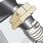
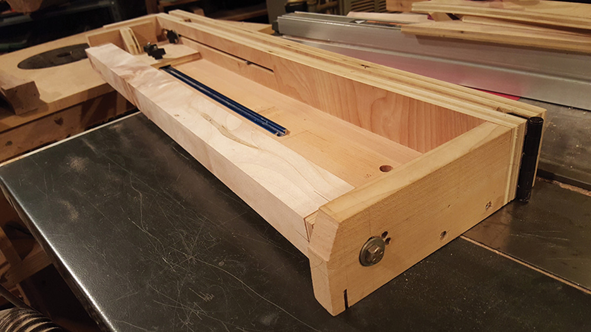
Indexed Tapering Jig
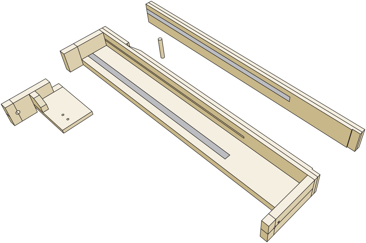
Recessed area on frame accommodates dowel so jig can have zero taper if necessary.
To solve the puzzle of how to cut tapered, hexagonal legs, I designed a taper-cutting jig that cuts the facets in six passes on my table saw. It works a lot like the indexing head on a lathe. The jig holds the leg on its axis so it can be turned at pre-set angles and adjusted to different tapers and leg lengths. It also holds the leg in place for mortising and sanding.
The jig is a simple frame. At one end is a movable carriage that has a hole and a threaded insert for a mounting bolt that goes into the top of the leg. At the other end is mounting hole plus a 1⁄4” indexing hole that will lock in a particular angle of rotation.
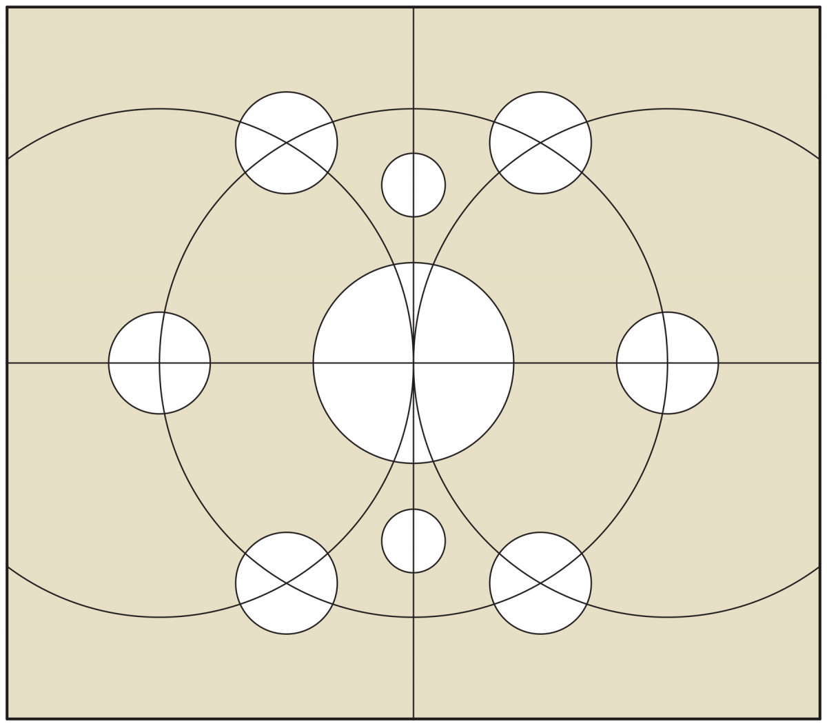
Jig Cartridge
The rotation of the leg is controlled by a “cartridge” made of 3⁄4“-thick plywood. The cartridge has a threaded insert in its center that’s surrounded by six equidistant holes (one hole for each face of the six-sided leg). The cartridge is screwed to the bottom of each leg. To lock in an angle of rotation, you’ll pass a bolt through the jig’s indexing hole and into one of the holes in the cartridge.
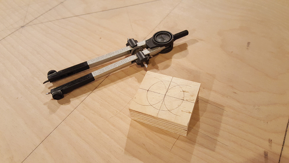
Three radii for six sides. Use a compass to draw a hexagon the old fashioned way – by drawing intersecting circles.
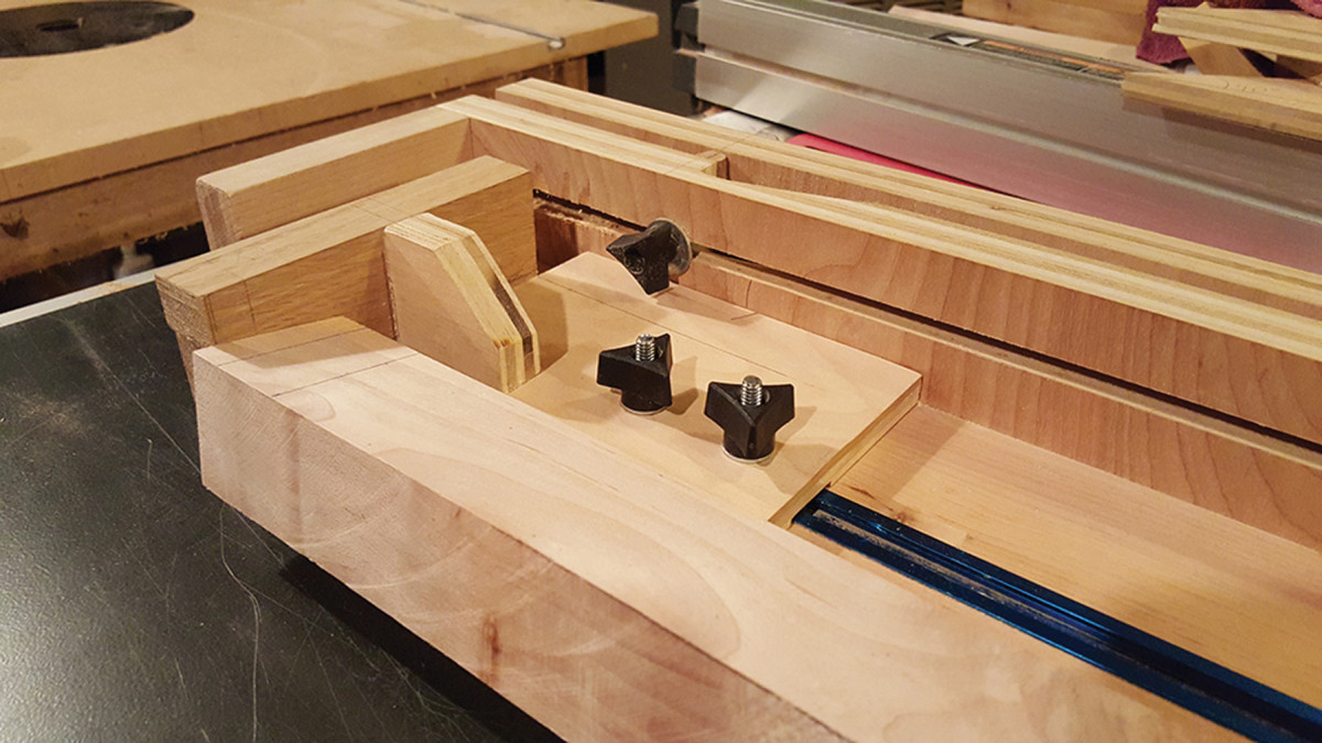
The jig’s frame is attached to a second fence with a door hinge at the end that allows you to adjust the taper angle. A particular taper is locked in by wedging a dowel between the frame and the fence and locking it in place with a bolt that grabs some T-track in the second fence.
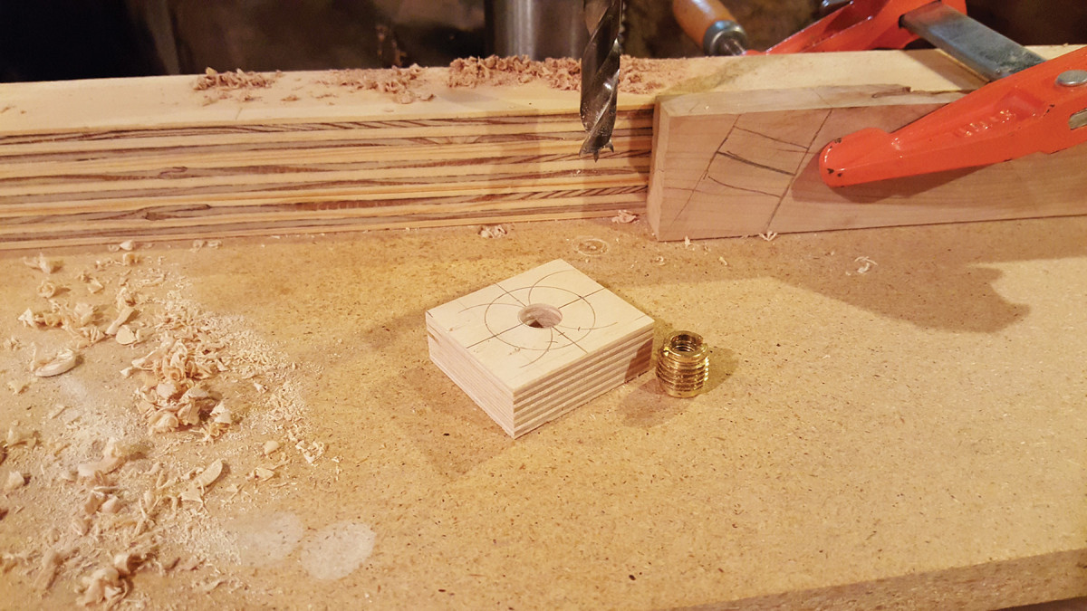
For the mounting bolt. Drill a 1⁄2″-diameter hole for a brass threaded insert.
To cut the tapers, screw the cartridge to the foot of the leg. Bolt the top and bottom of the leg to the jig, lock the carriage then insert a 1⁄4” bolt into one of the six holes in the cartridge. Make the cut and loosen the carriage bolt. Pull out the 1⁄4” bolt part way, then turn the leg while putting pressure on the bolt. When the next hole lines up, push the 1⁄4” bolt in and tighten the jig to make the next cut.
— MR
Make the Tapered Legs
The foot in the jig. The leg is attached by a bolt that goes through the jig and into the threaded insert on the cartridge, which is screwed to the leg.
With the leg blanks milled to the sizes in the cutting list, draw a 3⁄4“-diameter circle on the tops to define the tenons. Using a crosscut sled at the table saw, cut the shoulders for the tenons because it’s easier with the blanks still squared. Cut the shoulders 11⁄2” from the top of each leg.
Drill a 5⁄16” x 3⁄8“-deep hole in the top end of each leg to mount it to the indexed tapering jig.
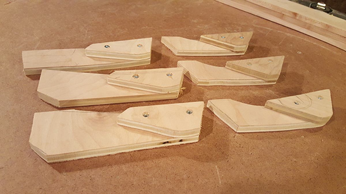
On the foot of the leg, attach the cartridge you made for the tapering jig with two #6 x 1″ screws. Fasten a test leg to the jig.
Rotate the leg and insert the 1⁄4“ indexing bolt through the jig and into the cartridge to lock the leg at the correct angle in relation to the table saw blade. Tighten the mounting bolt for the cartridge.
At the top of the jig. The carriage can be adjusted for legs of different lengths.
To get the proper taper, the best method is to lay out the taper on your test leg then sneak up on the correct pitch, using the layout lines as a guide.
With the jig firmly against the table saw’s fence, cut one facet of the leg. Loosen the mounting bolt, turn the leg to the next position and tighten the bolt again. I stopped the cut just before the blade reached the cartridge, then I pulled the jig back. The waste will still be attached near the cartridge, but it can easily be broken off.
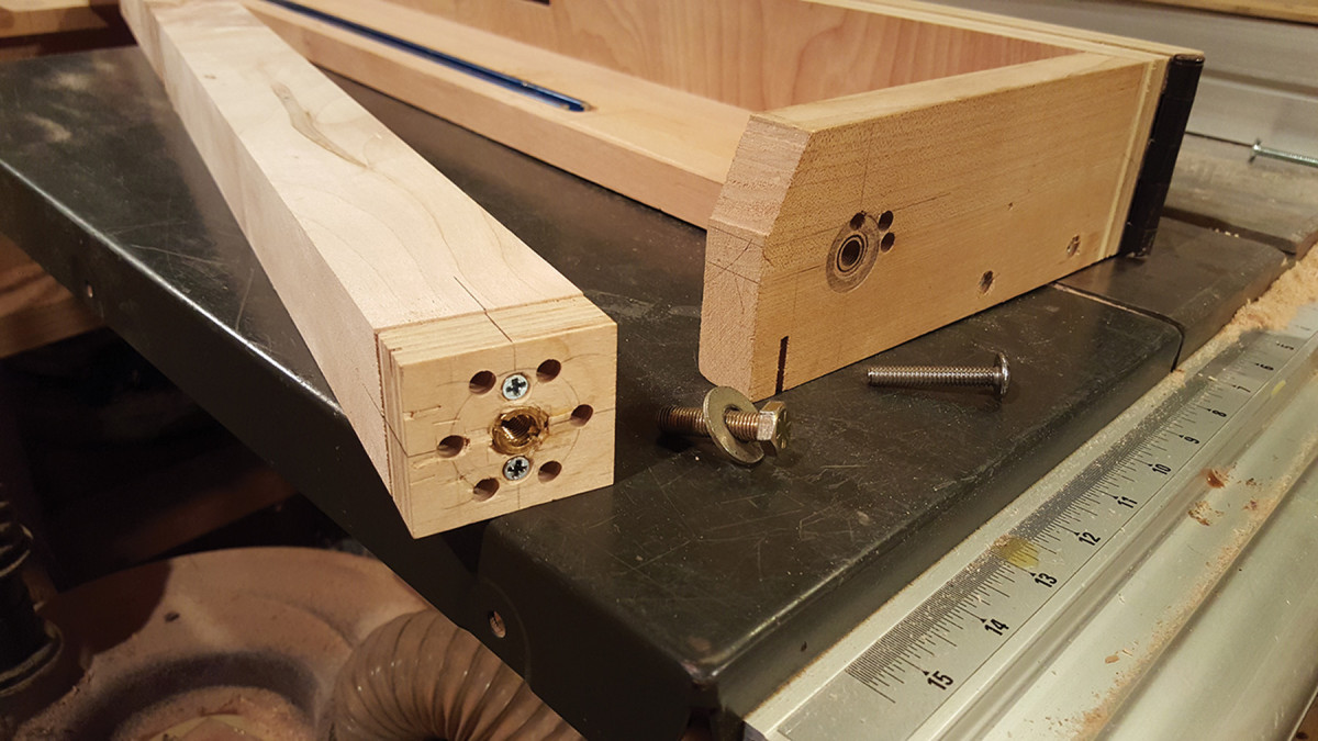
Screwed on. Attach the cartridge to the leg and it’s ready to bolt into the tapering jig.
After tapering all three legs, put them aside without cutting them to length. You’ll be putting them back into the jig later for mortising and sanding.
Make the Stretchers
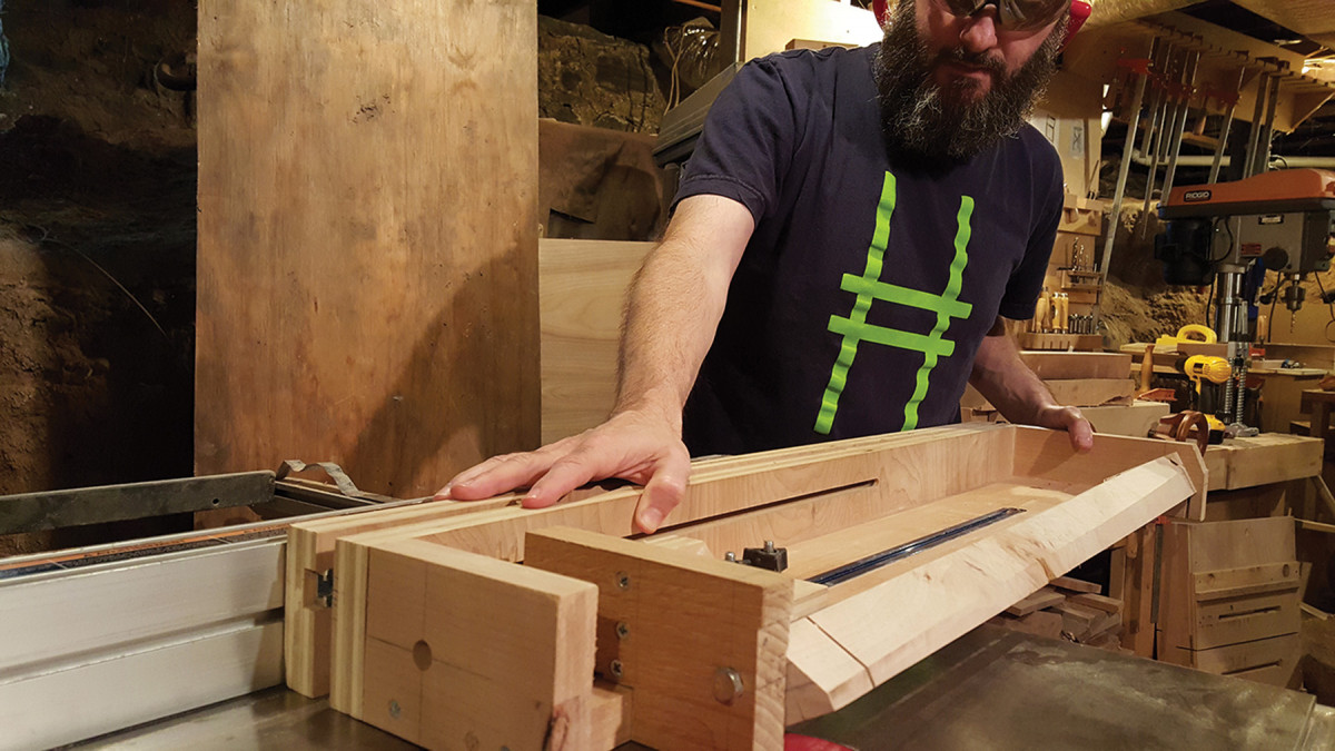
Go time. With the leg blank installed in the jig, cut the tapers in six passes.
Clamp straightedges along the lines for the legs’ inner faces on the drawing and use a digital protractor to measure the angles where the stretchers meet the legs. I made a dedicated sled for my table saw to cut these angles, but if you’re just making one table, a miter gauge or chop saw will suffice.
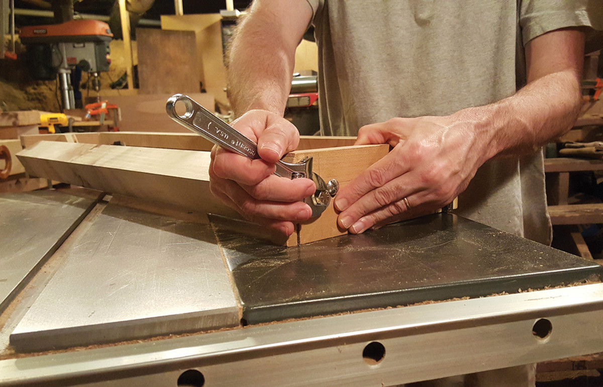
Tighten, then cut. Between passes, loosen the mounting bolt and remove the 1⁄4″ indexing bolt before advancing to the next position.
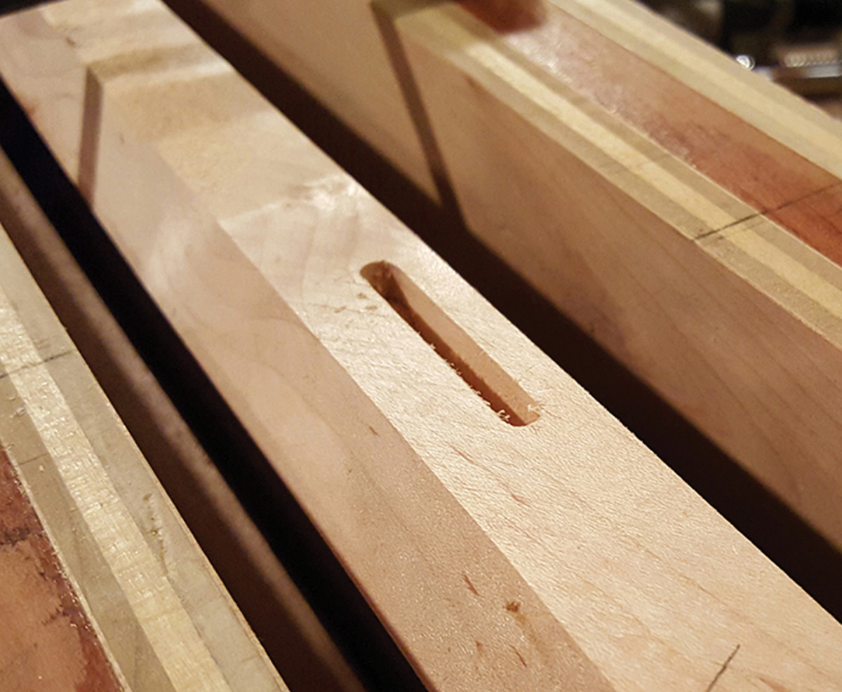
On the drawing, mark the centers of the mortises so you avoid short grain in the stretchers. Cut these mortises with a router on the ends of the stretchers, using your drawing as a guide.
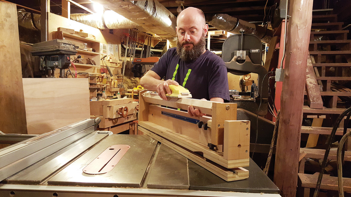
Sand as you go. The jig holds the legs in the perfect position for sanding and mortising.
The mortises should be 3⁄16” wide, 15⁄8” long and 3⁄4” deep.
Cut the curves on the stretcher using a router table, a plywood pattern and a flush-cutting bit.
More Leg Work

Double duty. This sled allows me to cut each angle on the stretchers without any adjustments.
Make a story stick to transfer the mortise locations from your drawing to the three legs.
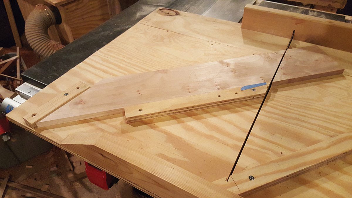
The stops are simply screwed in place.
Put a leg back into the tapering jig and turn the facet accepting the mortise upward. It’s easy to confuse the upper and lower mortises, so I marked them with blue tape.
To cut these mortises, I made a simple plywood box that encases the leg to give a larger bearing surface for the base of the router. Using your plywood pattern to determine the locations, mark the centers of the mortises on the jig. Cut the mortises for the legs using the same depth setting and lateral stops you used with the stretcher mortises. As to the locations of the mortises: For right front leg, the center of the mortise is 51⁄2” down from the underside of the top on the inside face. The center of the mortise on left front leg is 167⁄8” down from underside of the top on the inside face. Sand the legs while they’re still in the tapering jig.
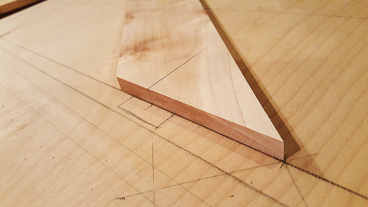
Drawing, meet stretcher. With the angles cut, place the stretcher on the drawing to find the location for the mortise.
Create the 3⁄4“-diameter round tenon on the legs. Dry-fit the legs and stretchers together with the floating tenons to make sure everything fits well, then cut the legs to length.
Time for the Top
Mortising. Because the mortises are 90° to the face of the leg there are a variety of ways to cut them. I put the leg back in the jig to hold it in perfect position to cut mortises with a plunge router.
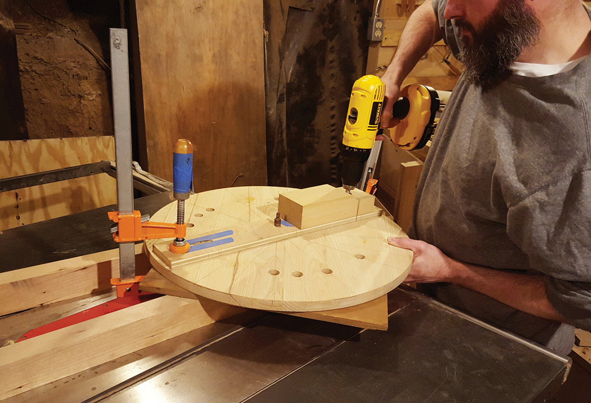
Glue up a 5⁄8“-thick panel and cut it into a 22″ x 22” square, establish the center and draw lines at 120° angles to mark the locations for the legs. Get the locations for the legs from the drawing, remembering to mark the locations on the underside of the top. I used a circle-cutting jig with a router to cut the round top at a diameter of 201⁄4“.
Put it all Together
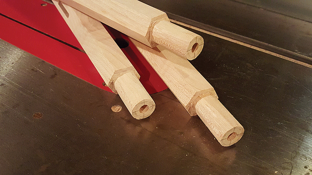
No lathe? Use a handsaw and files to make round tenons.
Use a scrap piece of plywood with reference lines transferred from the plywood drawing for a test run for drilling the holes for the legs.
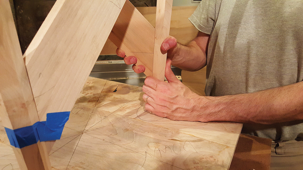
Test run. With mortises cut on the stretchers and the legs, dry-fit the table together with its floating tenons.
To drill the mortises, I used a jig similar to a circle-cutting jig that is crossed with a doweling jig. Cut a piece of 1⁄2“-thick scrap plywood to 3″ wide and 20″ long. Mark a line across the face and edge at 10” and drill a hole to accommodate the center pin used with a circle cutting jig.
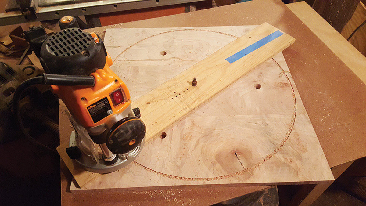
Simple but effective. A circle-cutting jig doesn’t have to be fancy to produce accurate results.
Draw a centerline along the length of the plywood and carry this line around edges.
Drilling jig. Here, I’m testing my drilling jig setup on a mock-up of the tabletop.
On the scrap top, drill a stopped hole on the underside to accept the pin. Now bore a hole angled at 4.5° in a block of hardwood that measures 2″ thick, 3″ wide and 7″ long. This block will act as a bushing or guide for the drill bit. Mark a line at 63⁄4” away from the center hole on the jig. Attach the block of wood to the plywood with screws (not glue) so that the centerline of the hole lines up with the centerline on the jig.
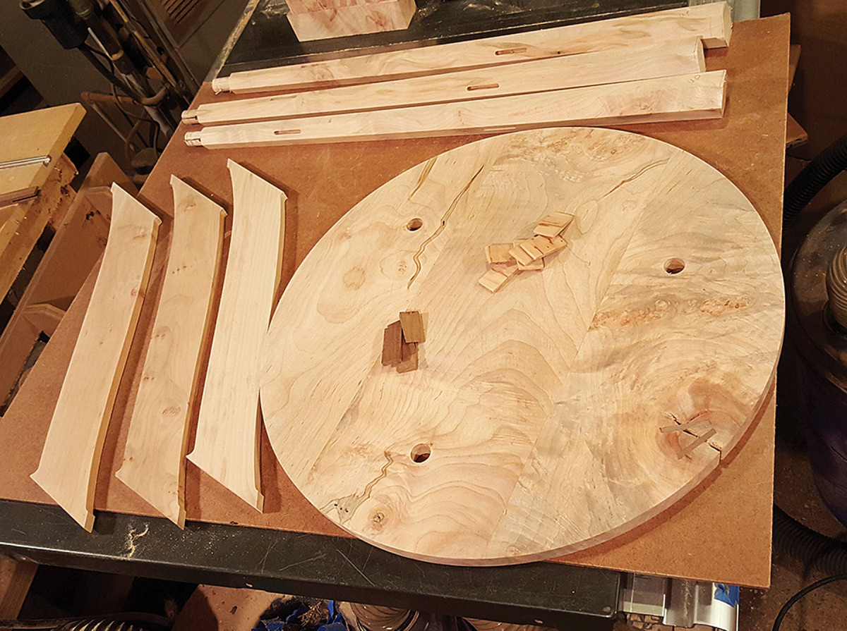
Seven not-so-easy pieces. When the going gets tough, it’s good to remember there are just seven parts (not counting the loose tenons and wedges).
Put the jig on the underside of the tabletop with the pin in the hole. Pivot the jig until it lines up with one of the three lines on the tabletop. Clamp the jig in place and bore the 3⁄4” hole with a hand drill on your dummy piece of plywood.
Clamp to clamp. Their shape may be funny, but these cauls make the glue-up a lot easier by giving the clamps parallel surfaces.
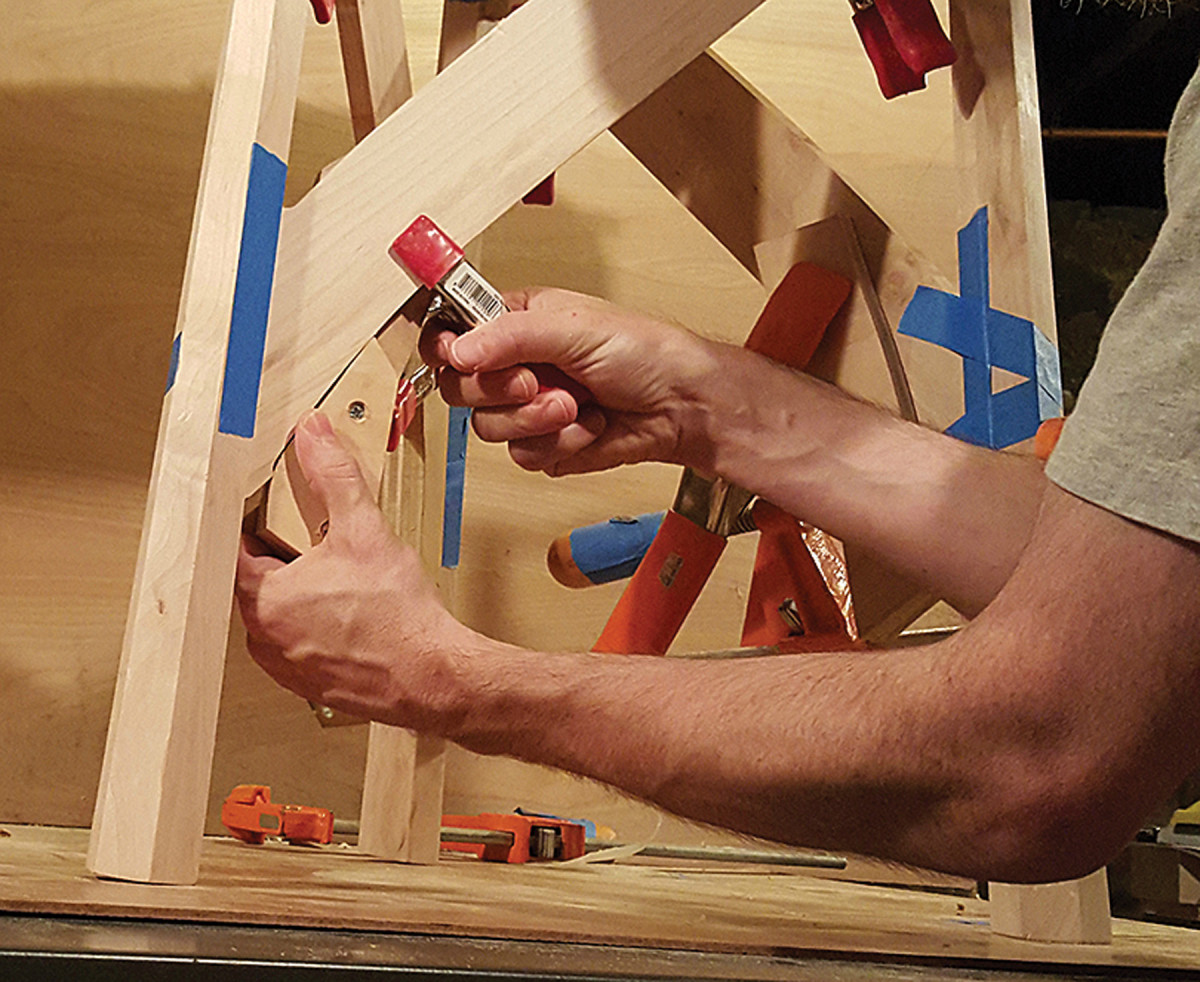
The cauls are clamped to the stretchers with spring clamps.
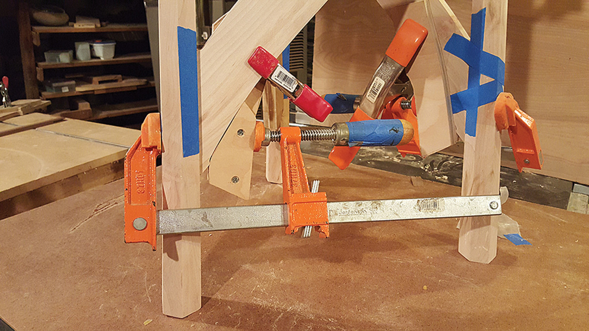
Then you can clamp the joint tight with an F-style clamp.
Dry-fit the legs and stretchers into the dummy top. If the dry-fit has gaps, unscrew the block of wood, move it and reattach it. Drill holes on new lines on plywood until you achieve a perfect fit.
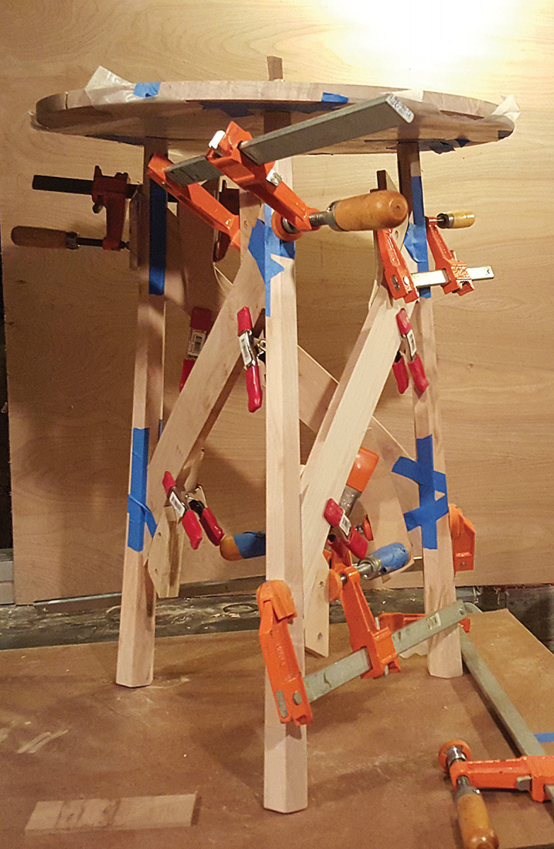
Clamp, then wedge. Apply clamps to the leg joints before tapping in the wedges.
When everything fits, bore the mortises in the real top. Patience will pay off here. Repeat this until you have an exact fit. Cut slots in the tops of the leg tenons to accept wedges.
The glue-up for this table can be a challenge because of the angles, so I made cauls to give the clamps somewhat parallel surfaces to work with. Wedge the tenons during glue-up and trim the tenons flush to the top when the glue is dry. I used crisscross wedges in homage to the original.
I finished this table with a simple wiping varnish, sanding between coats until I achieved a nice build and sheen.
Plan: Download a SketchUp model of this project from our 3D Warehouse.
Here are some supplies and tools we find essential in our everyday work around the shop. We may receive a commission from sales referred by our links; however, we have carefully selected these products for their usefulness and quality.