We may receive a commission when you use our affiliate links. However, this does not impact our recommendations.
 ‘Crossettes’ in the corners add flair to this mirror or picture frame
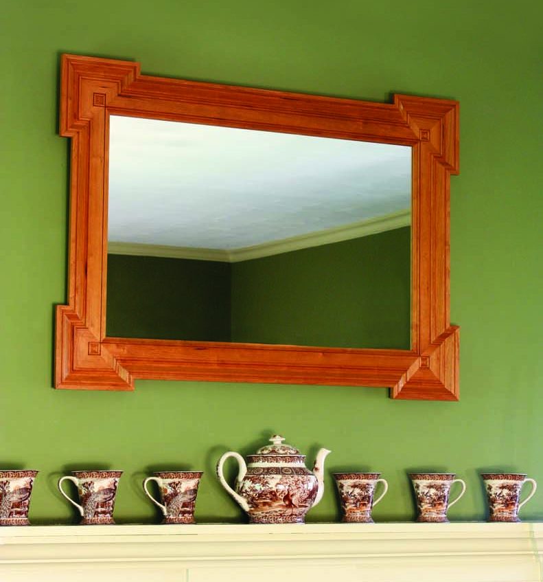 ‘Crossettes’ in the corners add flair to this mirror or picture frame
Architectural elements on which intersecting vertical and horizontal members extend beyond a simple lapped or mitered joint are said to be “crossetted.” The term has been used to describe any projecting corner treatment and has been a decorative staple employed by artisans and designers for centuries.
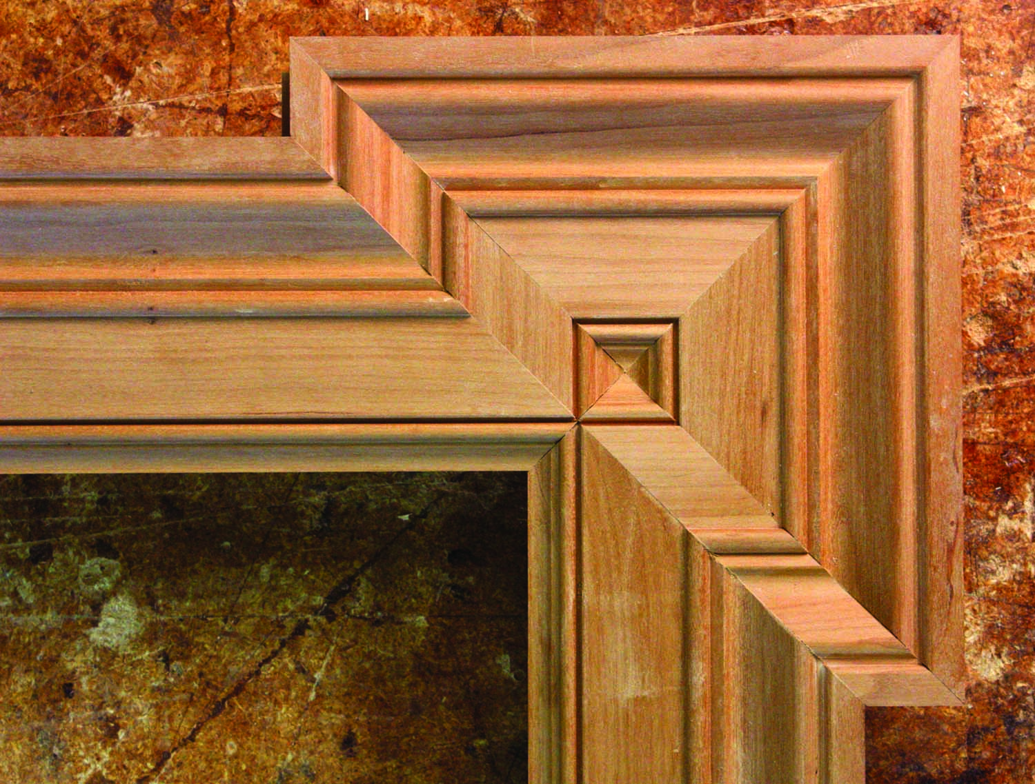
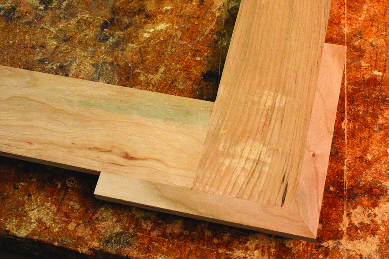
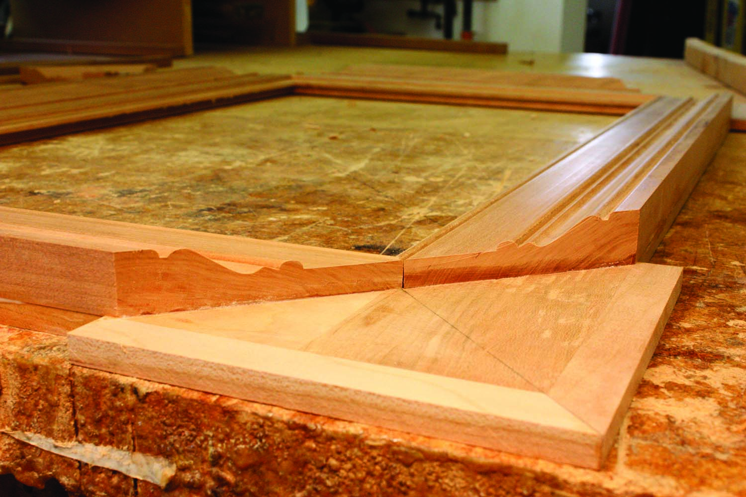
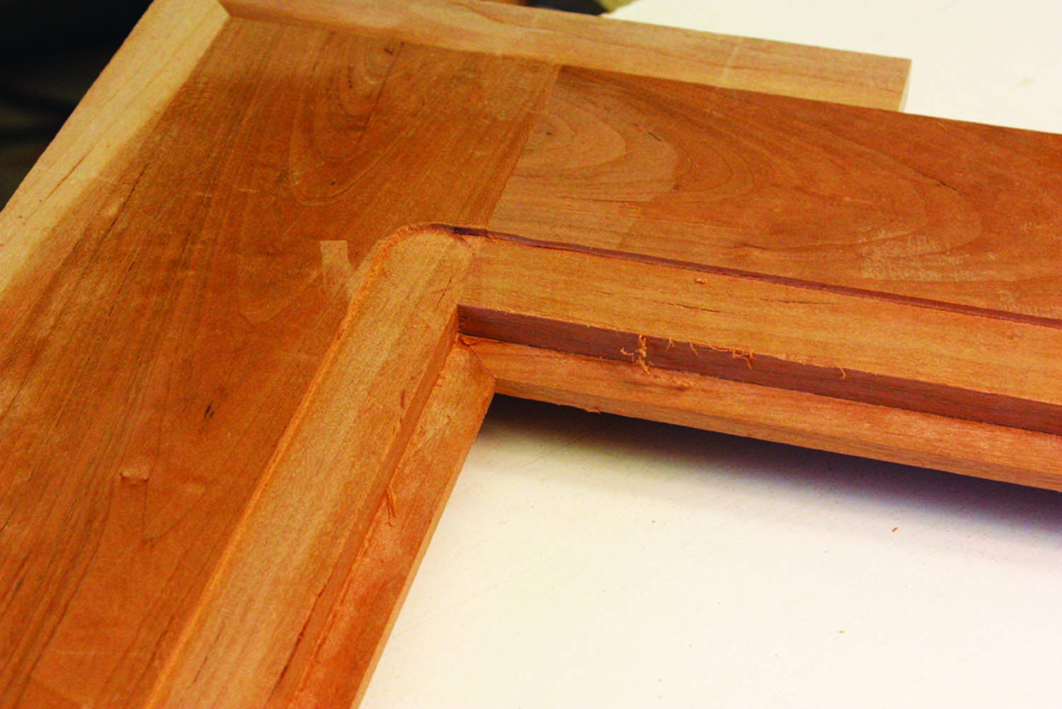
Hip to be square. A detail shows how the four parts of the crossette form a makeshift rosette at each corner. Although no finish has been applied here, the chatoyant differences of light reflected from the surfaces are already visible.
Of classical origin, crossetted elements were widely used in baroque and Georgian interiors, and they can be found on windows, mantels, doorways and other cased openings as well as on mobile pieces of furniture such as picture and mirror frames. Crossettes can even be found on more rustic pieces such as Arts & Crafts frames, for example, whose members simply overlap one another as they extend beyond the outside of the frame.
A crossette can be applied to one or both sides of a corner. When a crossetted frame is topped by a decorative entablature, the projection often occurs only on the vertical elements. Its effects are most striking, however, when the “square” formed by the extended members is completely enclosed by a decorative moulding.
The crossetted frame presented here is closely modeled after a cherry frame of Ohio origin made about 1840 that features a particularly ornate moulding. When wrapped around each of the projecting corners, the moulding creates a decorative square detail. In essence, each corner is itself a small square frame that has no aperture because the inside edges all meet at a single point.
An applied rosette can sometimes be found in the center of this square on more sophisticated examples of this type of frame. On this particular example, however, an ersatz rosette is cleverly created by the moulding profile. The inside beaded edge emphasizes the perfect square at each crossetted corner, which is harmoniously juxtaposed to the overall rectilinear shape of the frame.
Modern Methods
Good looks not required. Because the substrate will not be visible, lesser-grade materials and plain-Jane joinery are perfectly acceptable.
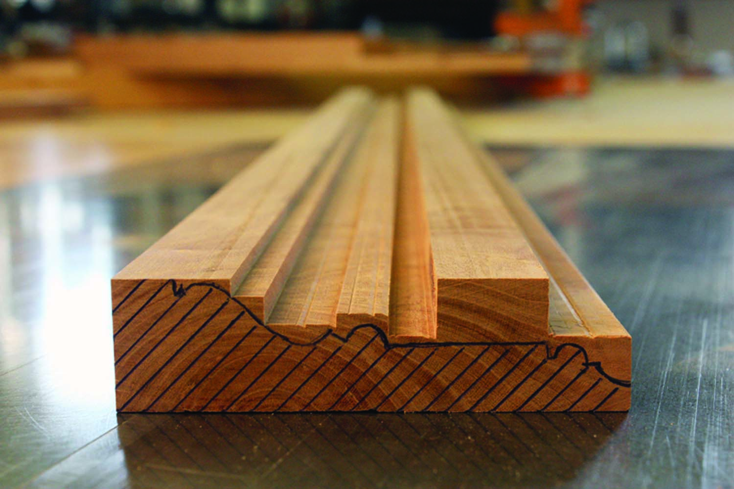
Although the moulding profile on the original was undoubtedly cut with moulding planes, I used stock router bits to create the profile for my frame. I did follow the two-part construction of the original frame, employing a thin subframe onto which the moulding is laid out and adhered. The outer back edge of the finished frame is chamfered to lighten its appearance and to make the “ears” stand out from the wall.
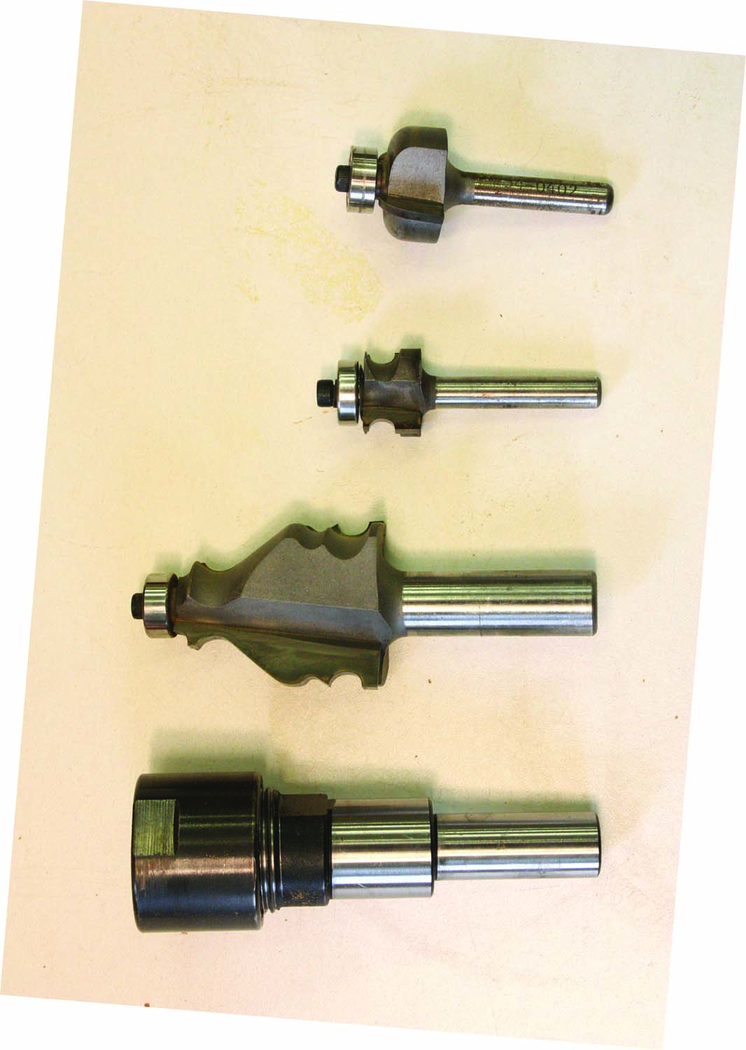
No two-bit operation. A collet extender (bottom) allows the complex moulding bit to be raised above the table. A 3⁄16″-diameter bead and 3⁄8″ cove are used to form the inside edge profile.
For this reason, I used No. 2 common cherry for the subframe – but any secondary wood can be used because it will likely be hidden in shadows or can be easily masked with stain. The subframe pieces are ripped 1⁄4” narrower than the moulding, creating an instant rabbet for the mirror when the two are glued face-to-face. On the assembled frame, the inside dimensions of this rabbet determine the size of the glass. I usually subtract at least 1⁄16” from the width and the height before ordering my glass.
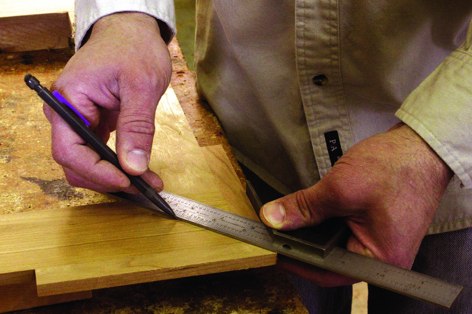
A simple layout. Two intersecting layout lines – one from the center to the outside corner, and another from inside corner to inside corner of each ear – are all that is required.
The subframe joinery is quick and dirty. A lap joint was employed on the original, but a biscuit – carefully centered in the 3⁄8“-thick stock – will provide adequate strength until the decorative moulding can provide additional strength, spanning the seams of the subframe.
After the four pieces of the subframe have been assembled, two strips of wood are mitered and glued to the outside edge of each corner to give the frame its crossette figure and to provide a backer for the projecting moulding.
Formulaic – Or Not
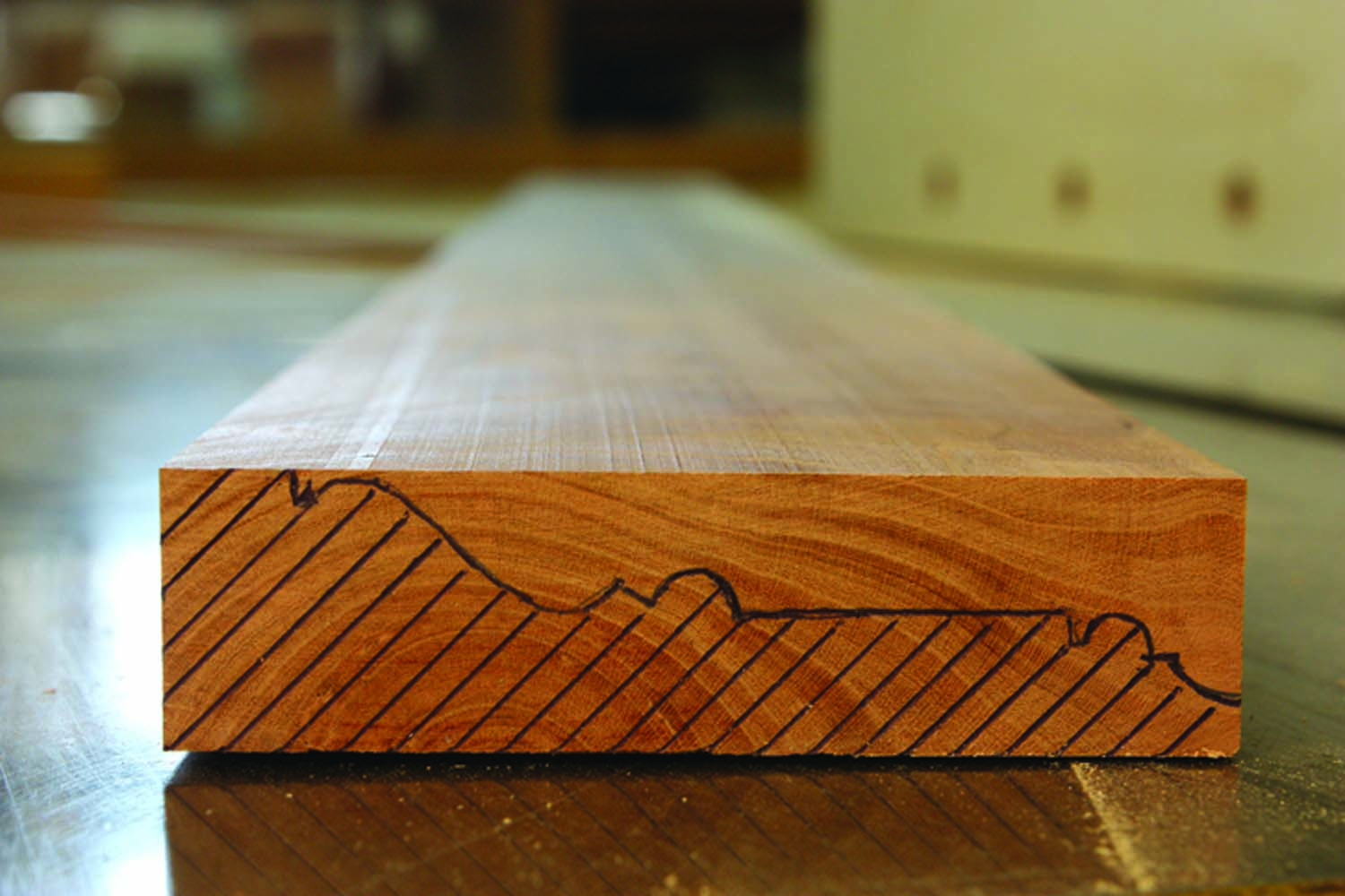
There’s a moulding in here somewhere. Laying out the desired profile on the end of one blank allows me to plan the safest and most logical sequence for removing the waste material.
A bridge to somewhere. The column of material on the right-hand side of the blank provides a second leg to ride the router fence below the cutter, which ensures a smooth, chatter-free finish.
The width and length of these strips are a function of the moulding profile – specifically the distance of the inside bead and fillet from the inside edge of the moulding. This measurement ultimately determines the width of the crossette returns. If D equals the distance from the moulding edge to the fillet, then the width (W) of each crossette return, according to Pythagoras, is expressed as W=√2(D2). I found the formula to be unnecessary, however, because the line of cut is predetermined by two points on either side of the return – one at the junction of the inside miter and moulding edge, and the other at the fillet located between the bead and the fascia.

Under pressure. Featherboards, above and in line with the cutter, provide the necessary pressure where it is needed most. They also encase the rather large moulding bit spinning inches above the table. A push stick is used at the end of the cut.
I smoothed both faces of the subframe with a handplane in preparation for the moulding and laid out in pencil the miter lines for the four pieces of moulding that make up the main frame. These pieces have typical inside miters that one expects to find on a picture frame. However, they also have reverse miters where they meet the crossette returns.
Outer Frame Construction
Sweating the details. The inside bead and cove are cut using a similar router table setup. The fascia of the moulding contacts a short fence while a featherboard supplies pressure over and slightly above the cutter. The bead is cut first followed by the cove.
I milled and smoothed the stock for the moulding (and prepped some additional stock to cover any contingencies). Each moulding blank is straight-grained cherry, 31⁄4” wide x 15⁄16” thick. On the end of one piece, I laid out the desired profile using the router bits shown on page 41. The profile consists of three main parts:
1. The outer complex moulding that is made up of several elements.
2. The inside cove and a bead that is flanked by fillets.
3. A fascia, or flat, sandwiched between the other two.
Taking sides. To index the moulding and hold it tight to the layout lines during glue-up, scraps are clamped at the layout lines.
The exact profiles and their locations on the finished moulding are not critical, save for the inside bead. The center of the bead is 7⁄16” from the inside edge of the moulding – that yields a 7⁄8” square inside the crossette. The wide flat area surrounding this square helps to emphasize the center detail.
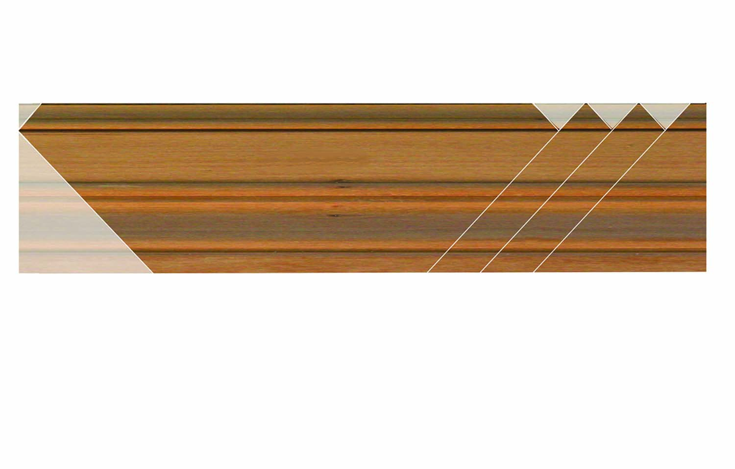
Sample layout for cuts. Before making any cuts, do a sample layout in order to economize on material.
I removed much of the waste with a 1⁄4“-wide dado set, especially around the raised moulded edge. Due to the required orientation of the bit used for the outer 2” of the moulding profile, I used a bit extender designed for router tables to reach across the width of the blank. Because the collet nut of the extension protruded above the table, however, I had to rabbet the inside edge of each moulding blank so it did not interfere with the routing operation. I left a column of material for support above the collet and below the cutter. Featherboards helped to hold the blank tight to the fence and table while routing the large profile.
Lend me your ear. After all four sides of the frame have been glued to the face frame, each ear is treated as an individual frame.
Once the outer profile was complete, I ripped off the support column and cleaned up the saw marks with a smoothing plane and card scraper. I then routed the small bead and fillet, followed by a 3⁄8” cove on the inside edge of each piece of moulding. A 1⁄16” fillet separates the bead and cove.
Miter Saw Instead of Miter Box
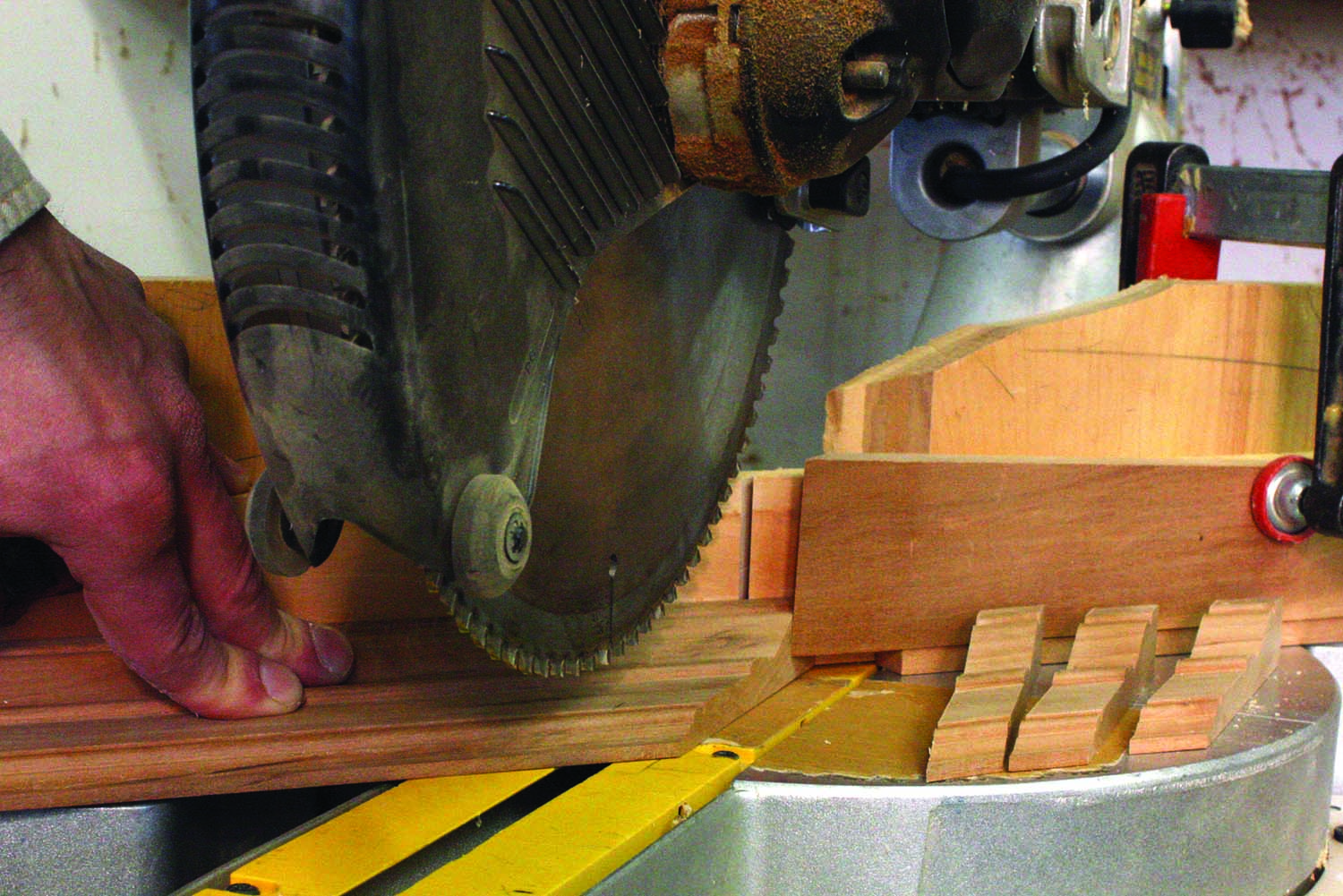
Mass miterer? A stop-block clamped to the fence allows identical parts to be cut with precision.
The miters of the original frame were likely cut in a miter box. All of the miters for my frame, however, were cut using a 12″ sliding compound miter saw with a fine-toothed finish blade that’s calibrated 90° to the table. Although the cuts were fairly clean, the reduced vibration of a smaller-diameter blade would have been even better.
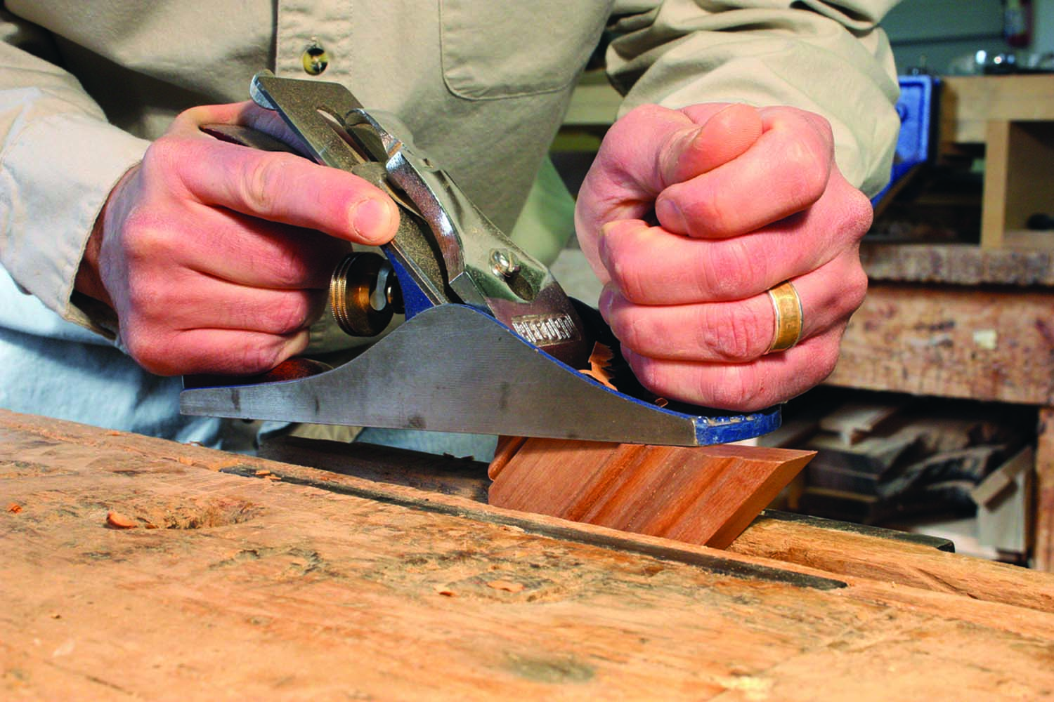
Balancing act. A very slight back bevel is planed on the mitered edges. This can be done quickly with a bench plane or block plane, with the workpiece securely clamped in a vise.
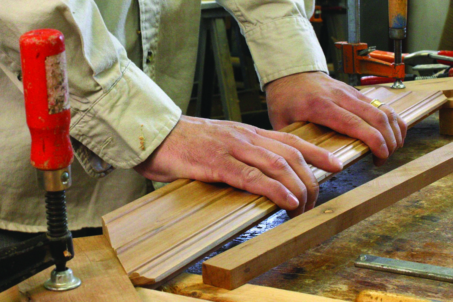
The four major lengths of moulding were cut first and glued to the subframe. To avoid wasting material, resist the temptation to cut an entire inside miter across the moulding blank. A few inches of moulding can be spared by carefully laying out the sequence of cuts in advance. Thin scraps of wood clamped to the subframe along the outside miter lines help to index the moulding to the subframe during glue-up.
After all four pieces of the moulding were glued to the subframe, I proceeded with the corner details. Each of the four crossetted corners consists of four pieces: a left-hand and right-hand return and two outside corners. A stop-block clamped to the fence of my miter saw ensured that each mitered return is the same width. To eliminate the propensity of the blade to grab the returns at the end of the cut, I stopped the blade while the teeth were still safely below the table of the miter saw. For efficiency, I cut all of the returns for the frame (and a spare or two) while I had the setup in place. Using the layout lines drawn on the subframe as a guide, I laid out and made the square cuts on the return pieces.
Temporary fix. A scrap clamped at the miter line provides a secure fence to align small pieces to while they are being clamped. After glue-up, pop the scrap loose.
The pieces of each crossette may require some fine-tuning to get the miters to close tightly. Plane a slight back-cut on the miters to ensure that the faces are as tight as possible.The small bevel also avoids squeeze-out at the miter during glue-up.
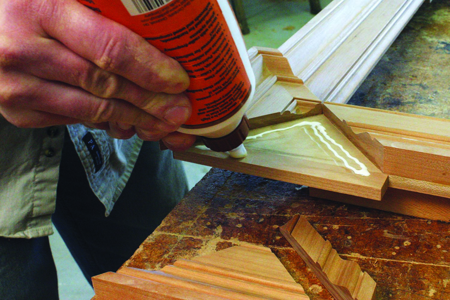
Crossette icing. Only the face of the moulding is glued. No adhesive is applied directly to the mitered edges – although some may creep up into the joint.
To trim the miters of very small pieces, I sometimes clamp my plane inverted in the shoulder vise of my bench and treat it as a jointer. For obvious reasons, precautions such as heavy leather or Kevlar gloves should be worn if you decide to use this method. A mitered shooting board is a safer alternative and, with the bed shimmed slightly for the back-cut, yields easily reproducible results.
Making the Crossettes
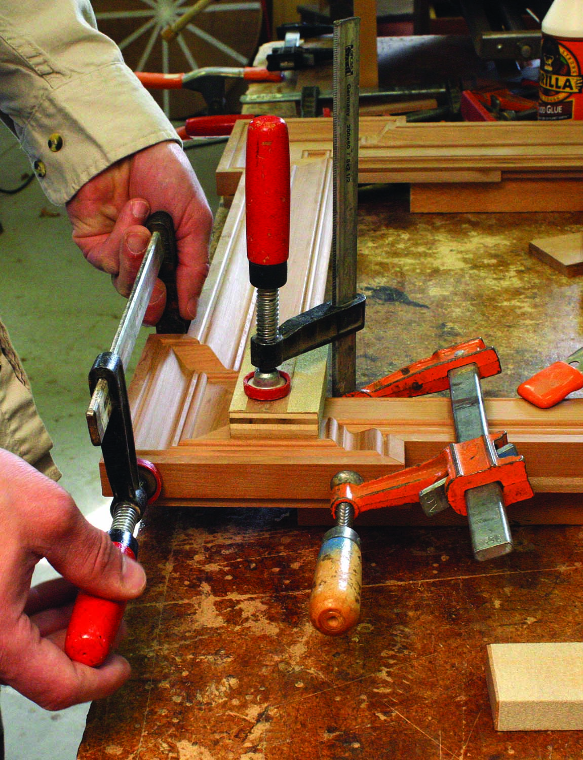
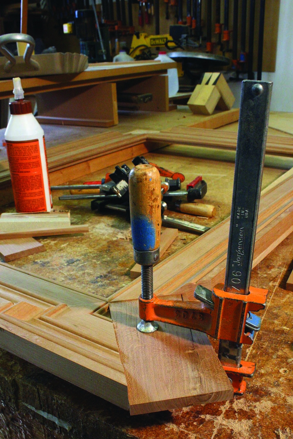
A nest of clamps. Clamps are added in a specific sequence to pull the pieces tight to one another.
The four pieces of each crossette were then glued in place – one return and one outside corner at a time. As when gluing the longer pieces of moulding to the subframe, a scrap clamped along the miter layout line helps to index the first two pieces of each corner during assembly. No adhesive is applied directly to the mitered edges, although some may creep up into the joint.
When clamping these pieces, apply pressure with a caul angled slightly toward the frame interior so they cannot slip. Then apply pressure across the miter and finally, straight down at the outside edges. After the glue has cured, the remaining two pieces of each corner are glued in place in a similar manner, although an additional clamp can now span the crossette miter. Clean up any glue squeeze-out at each step and blend uneven miters, if necessary, with scrapers or fine sandpaper.
The 1⁄8“-thick mirror is held in place with a slightly larger piece of 1⁄4“-thick stock or sheet goods inserted into a rabbet. A sheet of Kraft paper or posterboard inserted between the mirror and backer protects the back of the mirror from scratches.
Short fence. A thin scrap is screwed to the router table and acts as a guide for cutting the rabbet for the backer material.
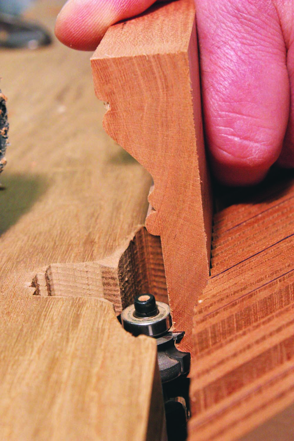
An 11⁄16“-wide rabbet for the backer is created with a 3⁄4” mortising bit at the router table. The width of the cut is determined by affixing a square scrap that’s the width of the rabbet from the arc of the cutter. Several passes may be required to achieve the proper depth for the rabbet. The thickness of the scrap should be just thin enough to allow the moulding to overlap it during the cut, but not so thin that the router bit extends above the top face of the scrap as you reach the final depth of cut. The upper corner of the scrap should ride in the mirror rabbet. After the four inside corners of the rabbet were squared with a chisel, I measured and cut an appropriate backer.
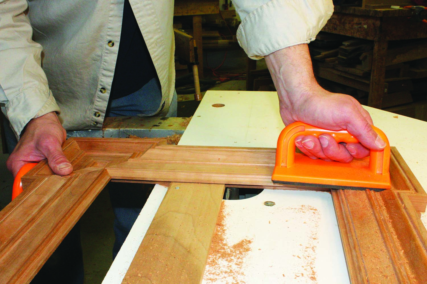
I used a large 45° chamfering bit to relieve the outside back edge of the frame. The 3⁄4” x 3⁄4” chamfer was cut in multiple passes. To complete the inside corners, I used mason’s miters. To shape these, I put the frame face down on a soft surface and marked the miter lines. I used a dovetail saw to establish the inside mitered corner then a bench chisel to continue the chamfer into the corner. The surfaces were blended with a scraper and fine sandpaper.
The Big Finish
Rabbets. The view of the backside of the frame shows the shallow rabbet created during the first pass. The bit will be raised and the frame sent around again, until the final depth is achieved.
With the frame ready for finish, I applied two coats of Waterlox wiping varnish to achieve a “dry” appearance that closely resembled the slightly dessicated finish of the original frame. With the finish cured, mount your hanger hardware and insert the mirror, Kraft paper and, finally, the backer that is secured with 1⁄2” screws. The classical lines and subtle details of the finished frame are an attractive addition to any room. PWM
Mark is a graduate of the North Bennet Street School. He works and lives in Sunbury, Ohio.
Here are some supplies and tools we find essential in our everyday work around the shop. We may receive a commission from sales referred by our links; however, we have carefully selected these products for their usefulness and quality.