We may receive a commission when you use our affiliate links. However, this does not impact our recommendations.
 From the Middle Ages until the dawn of the 20th century, wooden planes were the dominant bench plane form in the Western world. But when I started woodworking (in the hand-tool dark ages of the late 20th century), this traditional form seemed practically extinct. As I became interested in planemaking, I found plenty of information on laminated Krenov-style planes, but very little on traditional mortised planes.
Eventually, as I began to wrap my brain around these planes, I came to realize how enormously sophisticated and ingenious their design is. Virtually every feature has some functional purpose, even if it might not be immediately apparent. I came to think that traditional planes, in particular the British and American designs of the late 18th and early 19th centuries, represent the peak of the planemaker’s art.
Making a traditional plane poses challenges, but it’s a great way to hone your hand-tool skills. It requires a small tool kit, and while a few specialized tools are needed, they are of modest cost (and you can make most of them, if you’re so inclined).
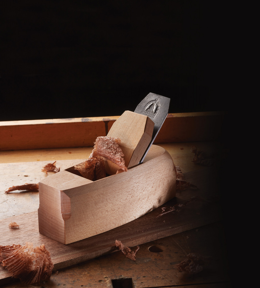
I’ll walk you through the design and construction of a traditional double-iron coffin smoothing plane (so-called because they resemble coffins, not because they were used in the mortuary industry!). A well built coffin smoother is an extremely useful and versatile tool – mine is rarely out of arm’s reach on the bench.
Materials
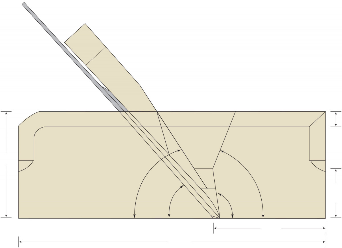
Section
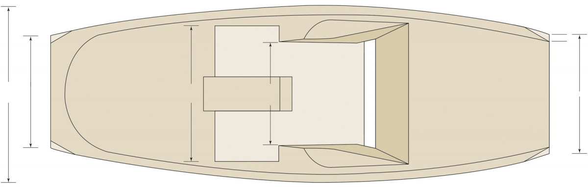
Plan
First, acquire a suitable double iron. Look for one that’s 13⁄4” or 2″ wide and at least 7″ long. The cutting iron should have at least 11⁄2” of usable length below the slot. It should also be tapered in thickness; most old irons are approximately 3⁄16” thick at the bottom and 3⁄32” at the top. Try to avoid irons that are badly pitted or twisted. I’ve found old irons at antique shops, swap meets and flea markets, including a “donor plane” with a ruined body but a usable iron. Another great source is eBay (particularly the U.K. site); search for “tapered double iron” or “vintage double iron.” And there’s a new source for the irons: Red Rose Reproductions, though you’ll have to make or buy the cap iron.
Next, you’ll need a billet for the plane. It should be at least 3⁄4” wider and 5⁄8” taller than your iron, and will finish at 7 1⁄2” long. If you can get it, use beech, the traditional wood for planes. If you can’t find beech, there are plenty of alternatives: hard or soft maple, yellow birch, apple and pear are all nice. Avoid softer hardwoods, such as mahogany, and very hard exotics. Ring-porous woods such as oak or ash are prone to chipping; however, with care a nice plane can made from these woods; there are plenty of historical examples in these species.
More important is how the annular rings are oriented. They should be as close as possible to parallel the sole, thus perpendicular to the sides. Avoid rift-sawn billets – they expand and contract unevenly, so you’ll have difficulty keeping the iron and wedge fitting well.
Finally, you’ll need a wedge blank that’s approximately 3⁄4” thick, 6″ long, and 1⁄8” wider than your iron. Grain orientation of wedge stock is a subject of some controversy. It’s clear that 18th- and 19th-century planemakers preferred stock that was quartersawn in its widest dimension, with the annular rings running perpendicular to the mouth of the plane. I make my wedges this way; I believe that the old makers preferred this orientation because it makes the wedge less likely to warp, and the quartersawn faces conform more easily to the iron and abutments, making for a better fit. A number of prominent modern planemakers, however, do the opposite, orienting the annular rings parallel to the mouth.
Tools for Planemaking
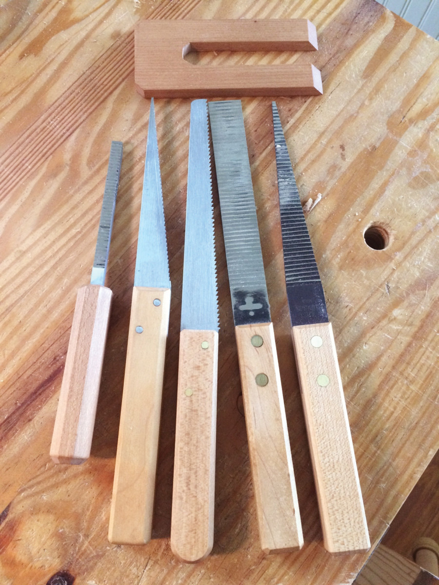
Tools for planemaking. From left are shown a 5⁄16″ mortise float, 1⁄8″ edge float, abutment saw, 1⁄8″ bed float and 1⁄8″ side float. At the top is a planemaker’s sinking-down gauge.
You’ll need a few specialized tools, but you don’t need to spend a lot of money. First, let’s talk about floats. The two floats I couldn’t live without are an 1⁄8” edge float and a 5⁄16” mortise float, both of which cut on the push stroke. If you are on a budget, you can make both of these yourself out of O1 steel (if you can file a saw, you can make a float). If you’re only making a few planes, you don’t even need to harden the steel. If you’d rather buy them, they’re available from Lie-Nielsen Toolworks.
If your budget allows, a bed float and a side float (again in push configuration) are nice to have. Making either of these by hand is an exercise in frustration, so buy them or do without. A great alternative is the “blunt chisel scraper” popularized by renowned planemaker Bill Carter. This is simply an ordinary chisel sharpened with a 90° microbevel. To hone the edge, hold the chisel vertically on a coarse stone with the bevel facing you, and pull the chisel toward you, repeating until you feel a burr. Lap the back, then repeat on your fine stone. Lap again and you’re done. Don’t strop. Scraper chisels are incredibly useful; I’ve got half a dozen in various sizes.
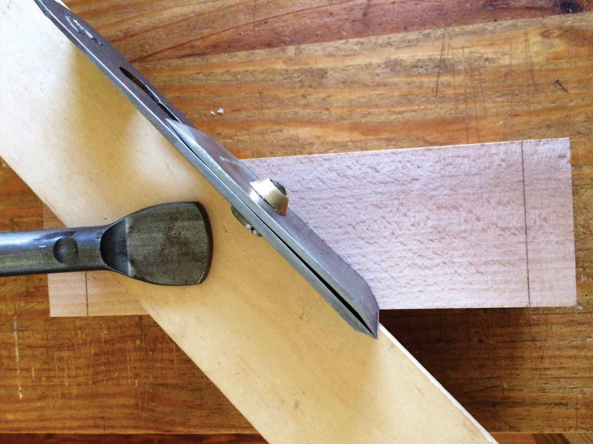
Clamp to scrap. It’s easier to accurately trace the outline of the iron if you first clamp a piece of scrap to the bed line.
A flush-cutting saw is also nice to have for cutting the abutments. Some people use the Japanese-style flush-cut saw. I prefer to make my own; the first one I made was a $5 drywall saw, with all the set pressed out and the teeth refiled for a rip cut. I’ve since made nicer ones out of 1⁄16“-thick saw steel. If you don’t have a saw, you can get by with the edge float.
One other tool you’ll need is a planemaker’s “sinking-down gauge.” This is simply a flat piece of scrap, about 1⁄2” thick, cut into a U-shape. Bevel the tips of the two forks so the gauge can fit all the way down to the mouth of the plane. To use the gauge, lay one of the forks on the bed (or breast) and compare the other fork to your layout lines.
There are a few other simple-to-make jigs, but these are optional and I’ll cover them as I go.
Clean Up the Iron
Before you start making your plane, clean up the iron. A roll of 3″- or 4″-wide coarse-grit adhesive-backed sandpaper, stuck down to a flat surface, will make short work of this. As with any plane iron, you’ll need to flatten the back. Flatten the bottom 3 1⁄2” or so of the front, too, so the plane will bed well. Before you do this, check the iron for twist. You can easily remove any twist by grabbing the bottom 2″ in a vise, putting a C-clamp on the top third of the iron, and twisting in the opposite direction. But don’t twist too hard. On laminated irons, only the bottom 2″ or so is hardened; the rest is mild steel or wrought iron so it’s fairly malleable.
Billet Prep & Mortise Layout
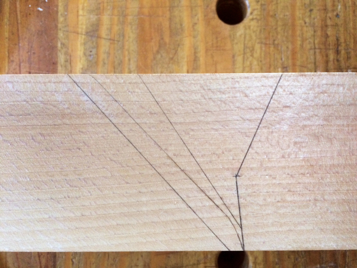
Completed layout, side view. Both sides of your billet should now look like this.
Make your billet flat, square and parallel. Traditional bench planes are typically square in cross section and about 5⁄8” wider and taller than the iron’s width, but for a coffin smoother, you need a slightly wider billet. Start with one that’s a bit long, and trim the ends later.
Study the grain to determine the correct orientation for your plane, and label the sides and ends. Traditionally, the bark side is the sole and the heart side is the top. The grain on the sides, if not parallel to the sole, should run downhill from toe to heel.
To lay out the mortise, start by marking the cutlines for the ends. On the sole, use a square and knife to scribe a line for the back of the mouth 2 5⁄8” from the toe. Set a bevel gauge to your desired bed angle (I typically use 47.5°, but anything from 45°-50° is fine) and with a pencil, mark the bed line on both sides (for all angles that follow, make sure you mark the angle on both sides before resetting your bevel gauge). After you’ve marked the bed lines, connect them across the top of the plane with a square.
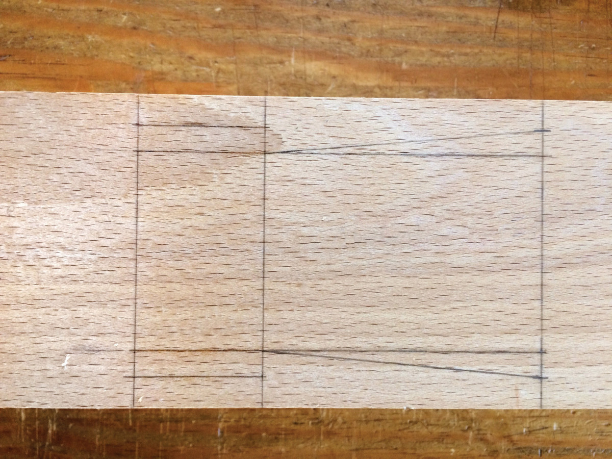
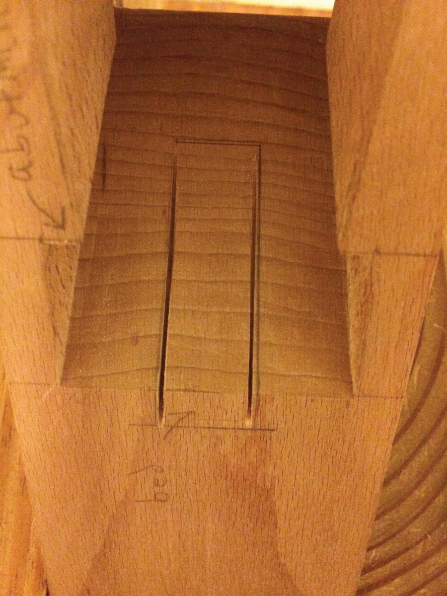
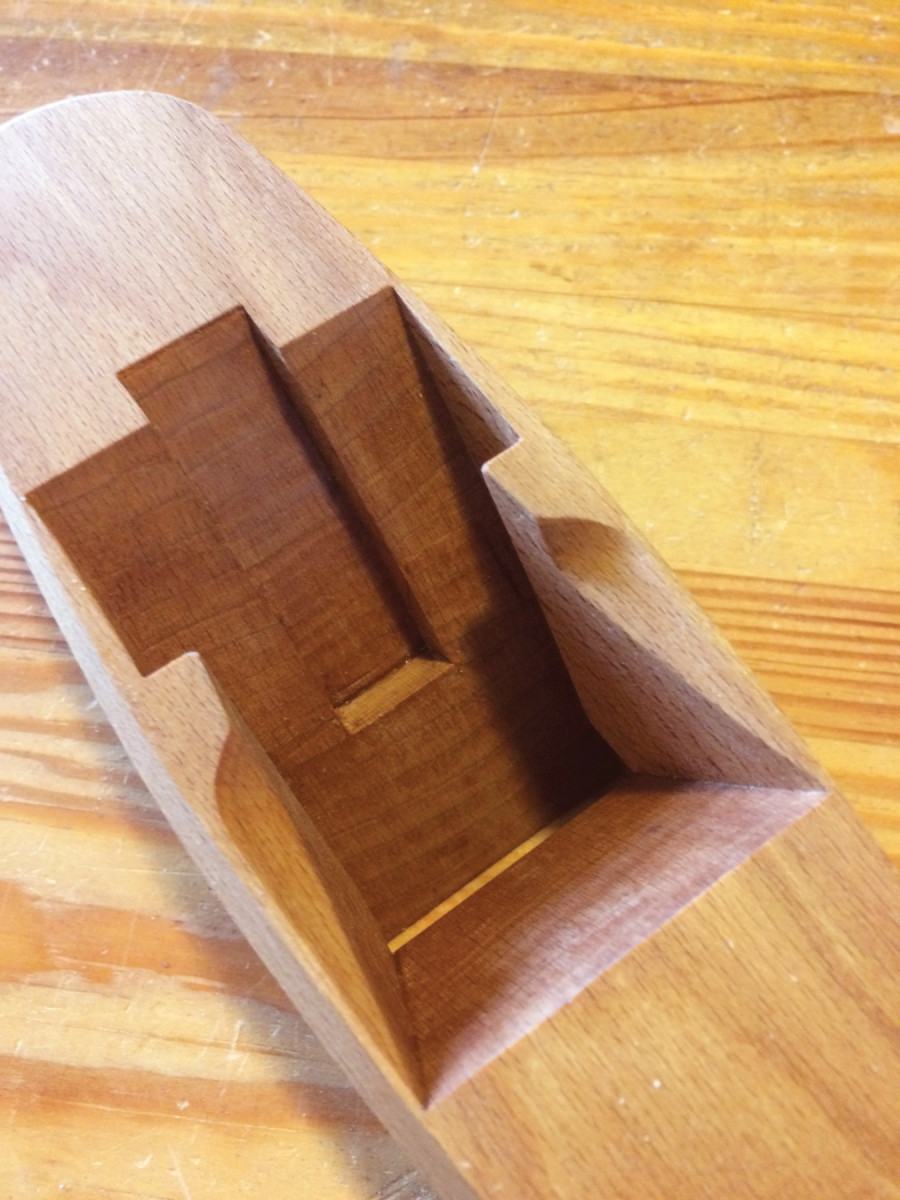
Completed layout, top view. The flared-out lines that connect the abutments to the breast define the escapement. Add these lines now, or wait until the rough mortise is chopped.
Next, lay the assembled double iron against the bed line and trace the front of the cap iron and tip of the cutting iron. Now you know exactly where the cutting iron will protrude from the sole, so mark the front of the mouth across the sole. Aim for a zero-clearance fit and err on the side of a too-narrow mouth; you can always open it up later.
Now mark the wear angle. On a double-iron plane, the wear needs to be much steeper than on a single iron, otherwise shavings will be trapped by the cap iron. Early double irons had steeper wears than the factory-made planes of the 19th century. By making the wear steeper, the early planemakers were able to have relatively tight mouths, whereas the later planes had shallower wears but very wide mouths, probably because it was easier to mechanize production this way. With a 47.5° bed, I use an 85° wear (relative to the rear of the plane – the angle is 95° relative to the front, as shown in the diagram).
Set your bevel gauge and draw the wear line, making sure the wear angles back toward the bed, not the other way! Mark a point on the wear line that is 11⁄8” above the sole. This point is the top of the wear, and it intersects with the breast. Set your bevel gauge to 65° (angled away from the bed) and scribe the breast line from the top of the wear up to the top of the plane. Use a square and connect the two breast lines across the top of the plane.
Now mark the abutments. Set your bevel gauge at 9° greater than the bed angle (56.5° for a 47.5° bed) and position the gauge about 3⁄32” forward of the highest point on the cap iron, just above where the cap iron curves down to meet the cutting iron. Draw the line down from the top until it intersects the wear. Do this on both sides, then connect the abutment lines across the top.
Now mark the width of the rough mortise. This should be 1⁄2” narrower than your iron, so for a 2″ iron, you want a 11⁄2” mortise. Draw the lines on both the sole and the top of the plane, and make sure the mortise is centered.
Finally, mark the width of the mortise between the bed and the abutments. I like this mortise to be approximately 1⁄16” wider than the iron at the top of the plane and 1⁄32” wider than the iron at the sole. I’d rather have the mortise a tad too wide than too narrow – you don’t want the iron to bind in the mortise or be difficult to adjust square. Measure the width of your iron at both the bottom and in the middle, where it emerges from the top of the plane; vintage irons are often slightly tapered in width as well as thickness.
Rough Mortise: Drill & Chop
Rough mortise. Here, I’ve completed the first pass on the far side to rough out the mortise, and am just getting started on the near side.
Before you start chopping, use a square and a marking knife to scribe lines 1⁄8” in front of the bed line and 1⁄8” behind the breast line; these define where you’ll rough-chop. Then use a chisel or a marking gauge and score the lines that define the sides of the rough mortise. This will keep you from tearing out big chunks outside your layout lines.
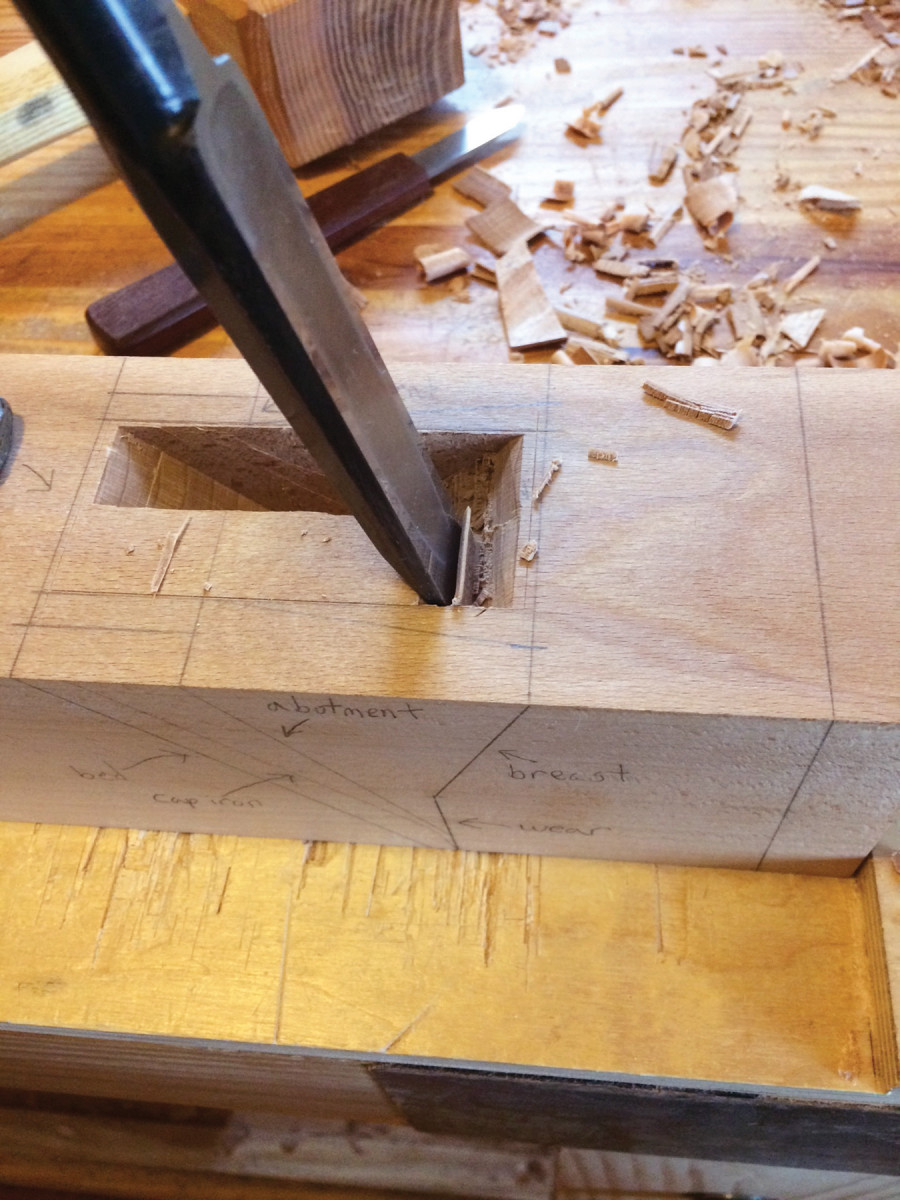
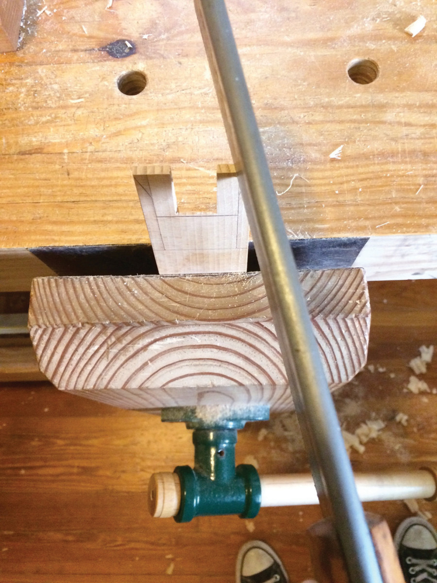
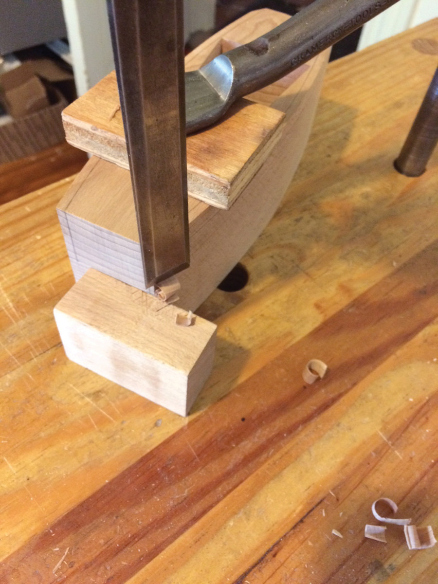
Use any sturdy chisel that is approximately half the width of the rough mortise. Start at the breast, about 1⁄4” behind the line. Make a small V then work backward, bevel down, until you’re 1⁄4” from the bed. Hold the chisel at about an 80° angle, as shown below. If you find the going gets too tough, flip the plane around and work in the other direction. Chop one side of the mortise from bed to breast, then do the same on the other side. Don’t worry too much about the angles at this stage; just make sure you don’t go too deep, and stay inside the lines.
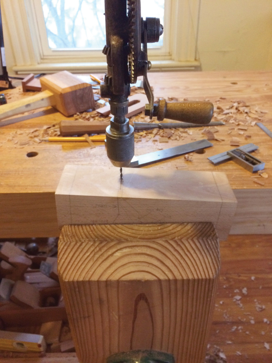
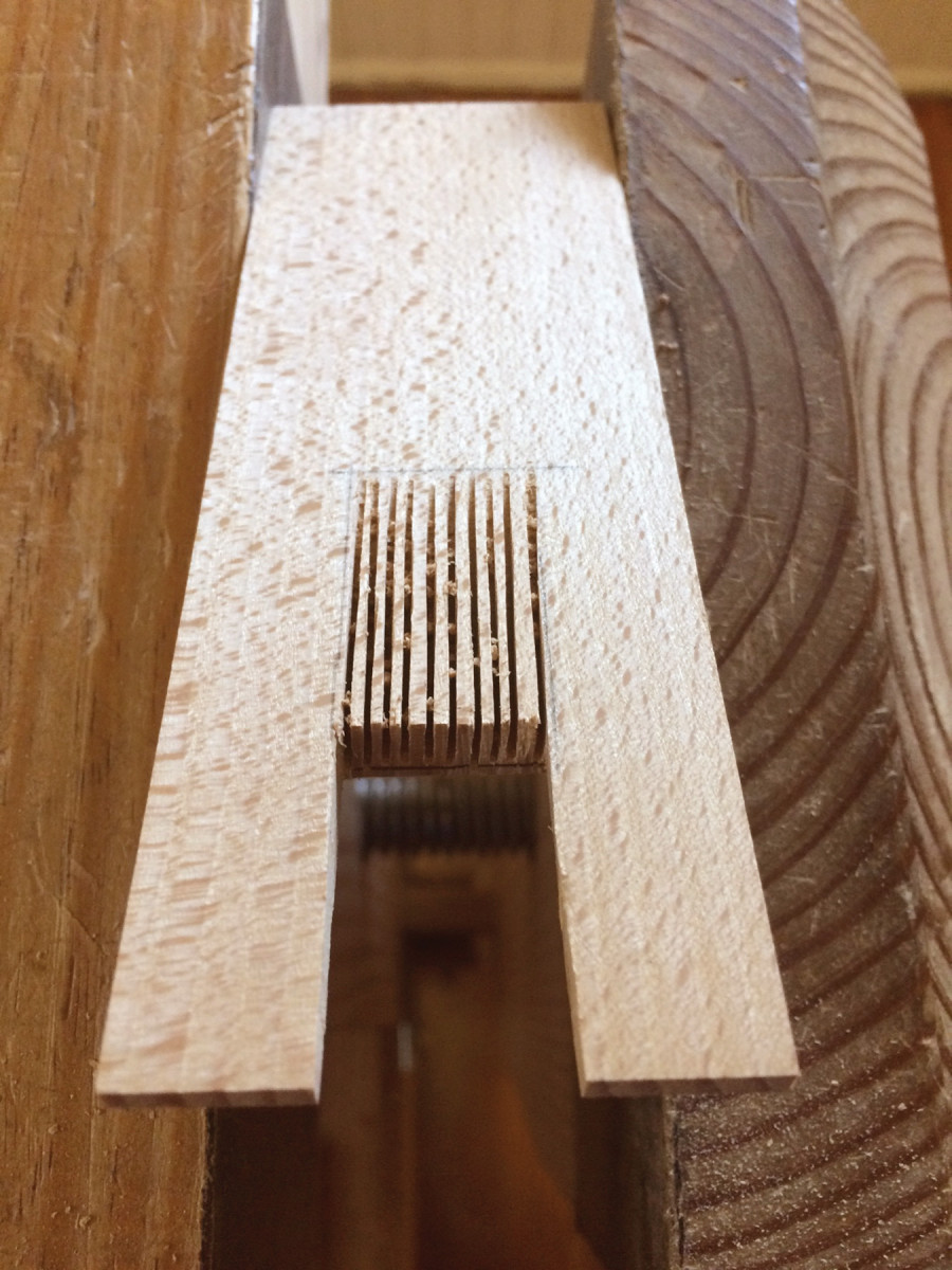
Drill the mouth. You’ll save yourself a lot of work if you can drill closely spaced holes parallel to the wear angle.
At this point, your mortise will almost certainly be too shallow, so start deepening it. You can either chop or pare, but keep working with the chisel bevel down; that will give you more control and you’ll be less likely to cut too deep. As you go, pare away the side walls and check your progress frequently with the sinking-down gauge.
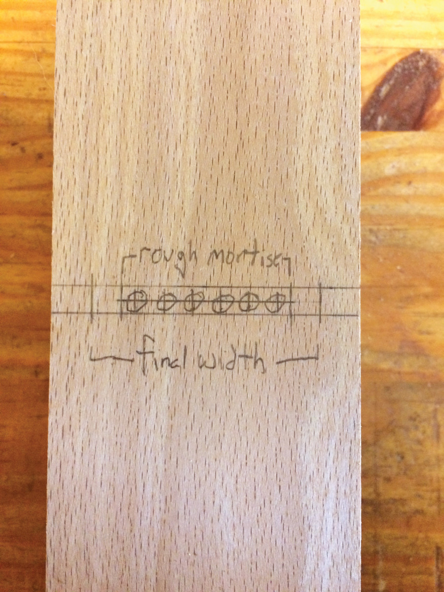
Above is the layout for the eight holes to waste out the mouth.
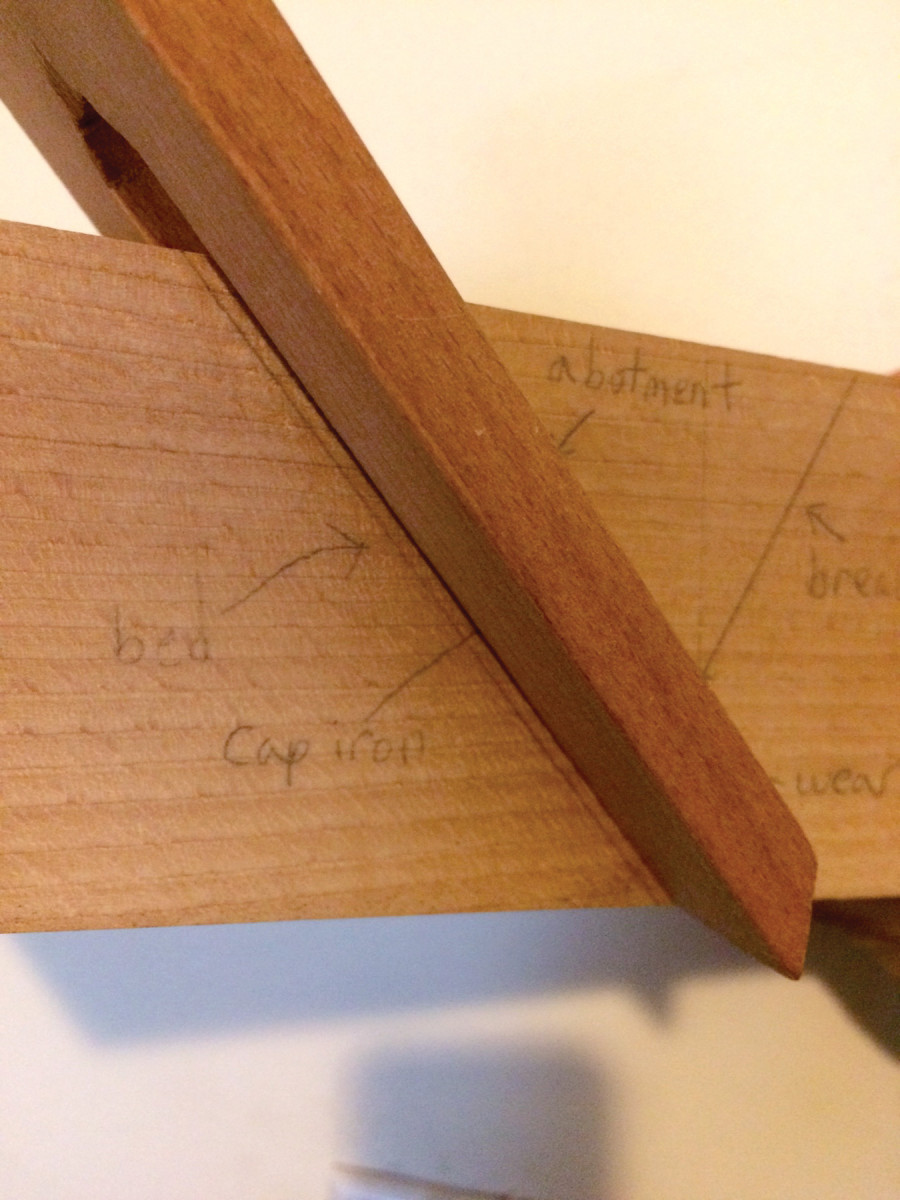
In the roughing-out stage, the bed and breast angles meet in a V at the bottom of the mortise. Later, you’ll incorporate the wear angle.
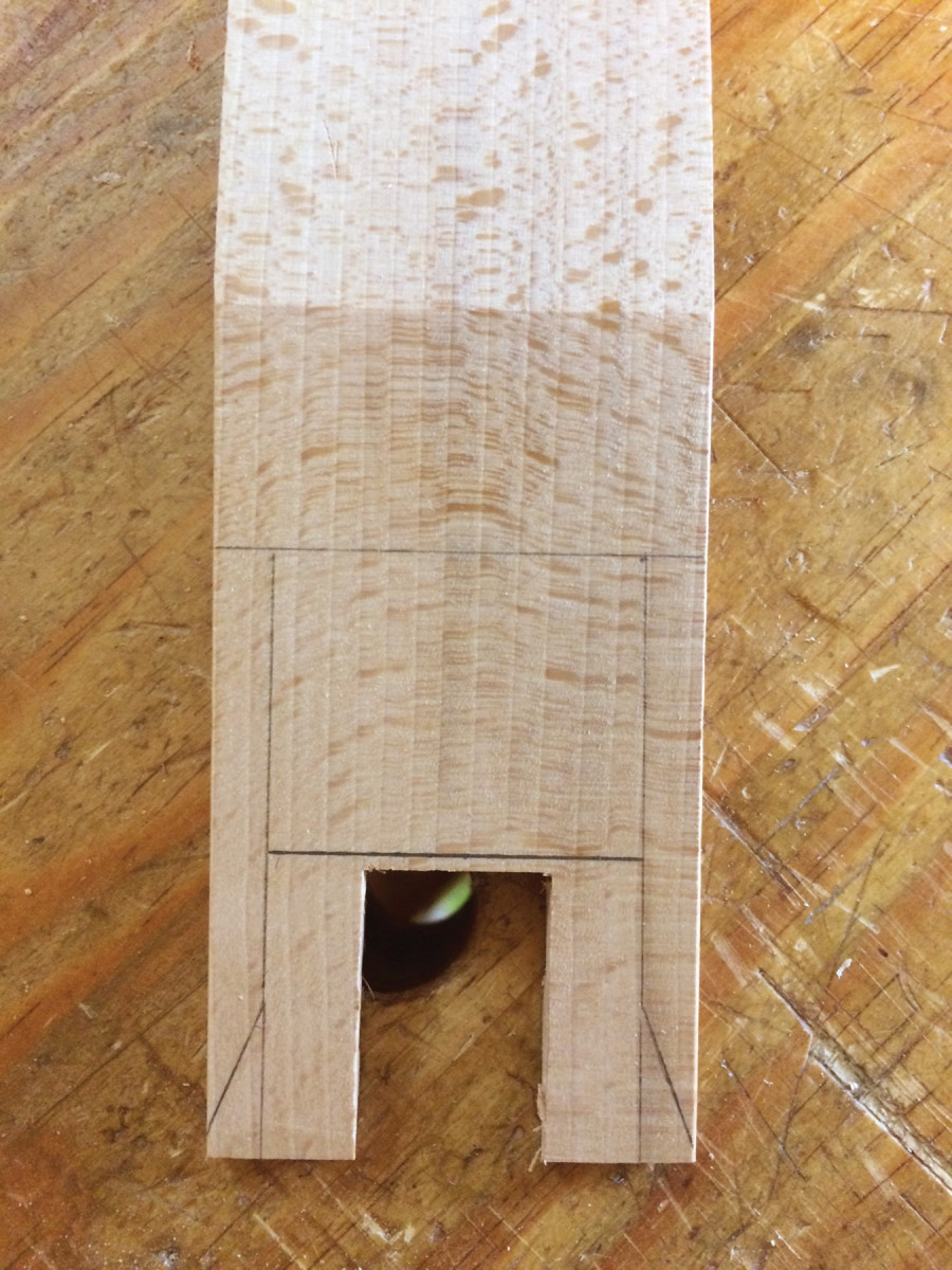
When the mortise reaches a depth of roughly 3⁄4” above the sole, flip the plane over and get ready to drill through the mouth. Scribe a line that splits the distance between the front and back of the mouth and lay out your holes on closely spaced centers. Make sure you stay inside the rough mortise (remember, the rough mortise is 1⁄2” narrower than the width of your iron).
Angle judge. The sinking-down gauge is invaluable for checking the accuracy of the bed and breast surfaces.
A drill press is ideal for this task, but you don’t need one. Hold the billet in a bench vise so that the wear line is vertical, and drill through with an 1⁄8” brad point bit . You may want to place a square on the bench for reference. If you miss on the angle, miss by angling toward the bed, where you have plenty of clearance.
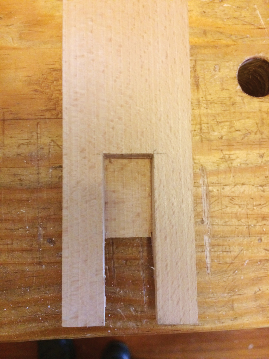
While you’ve got the plane upside-down, chop a mortise about 1⁄32” deep, just inside the layout lines of the mouth. This will help prevent blowout later on. Use your edge float to saw through the mouth. If the float won’t go through, chisel away some of the waste.
With the mouth opened, it’s time to clean up the bed and breast surfaces. Pare with a chisel, being careful as you approach the mouth opening not to slam your chisel into the wear surface too hard (this can cause the front of the mouth to chip badly). When you’ve gotten as close as you can with the chisel, finish up with a bed float or the blunt chisel scraper. To work aggressively with a float, raise the handle and use the front tooth as scraper. It also helps to skew the tool a little.
Whatever tools you use, keep working until the bed and breast are nice, flat surfaces. If you are confident, you can work right to your layout lines. If not, stay back about 1⁄16” – later, I’ll show a nifty trick with the edge float that will make nailing the bed angle easier.
After the bed and breast are cleaned up, finish the rough mortise by paring away the wear surface. Hold the billet in a vise so that the wear surface is vertical, and concentrate on keeping the chisel plumb. Finally, chop straight down along the line that defines the back of the mouth. Accuracy here will make fine-tuning the bed easier.
Saw the Abutments
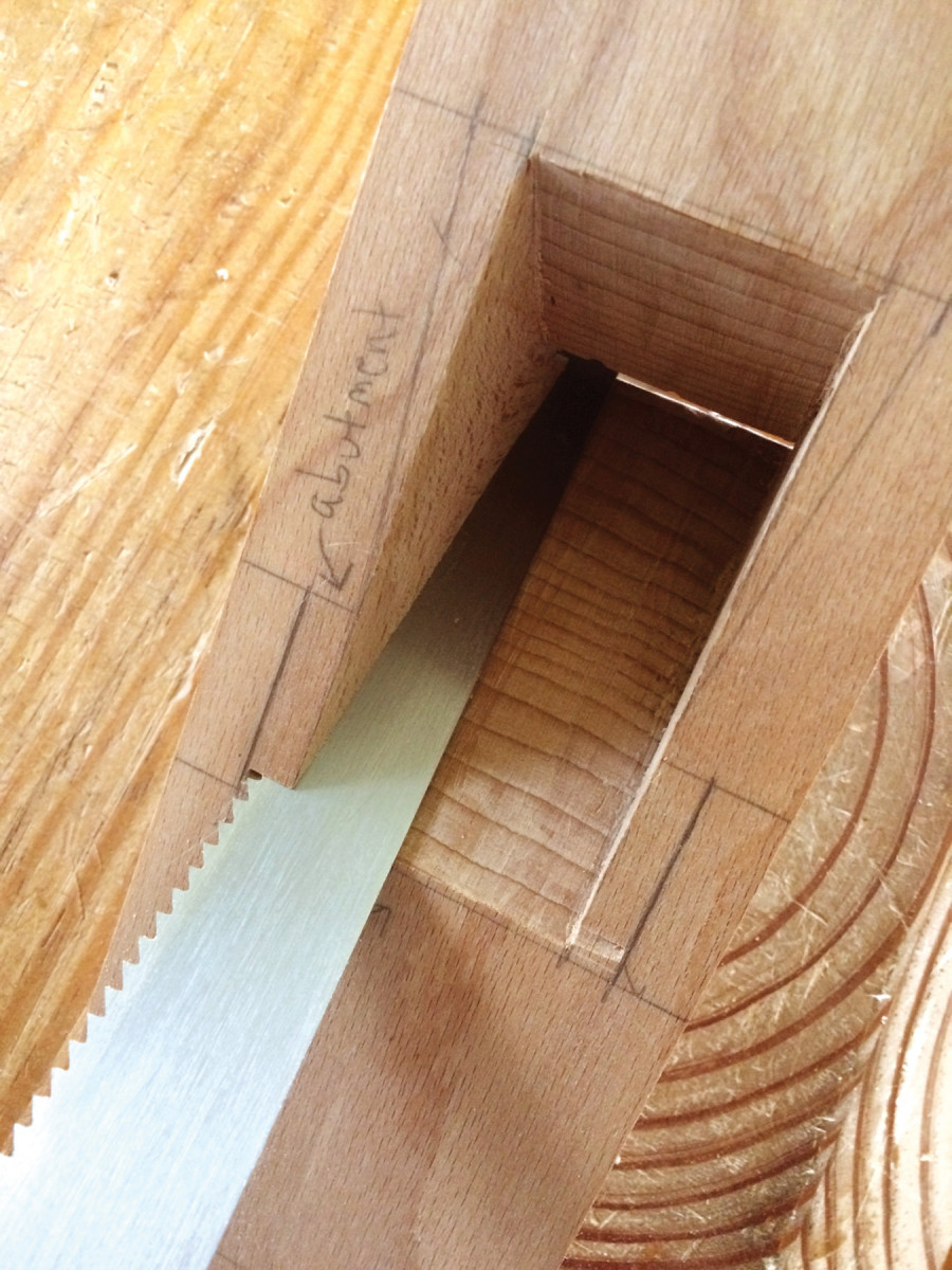
Use the bed as reference. For the first kerfs, cut just shy of the abutment layout lines, with your saw resting flat on the bed (this is why it’s important to first get that bed flat).
Now make three pairs of cuts with your saw or edge float. First, use the bed as a reference surface and cut just shy of your layout lines, leaving a bit to be cleaned up later.
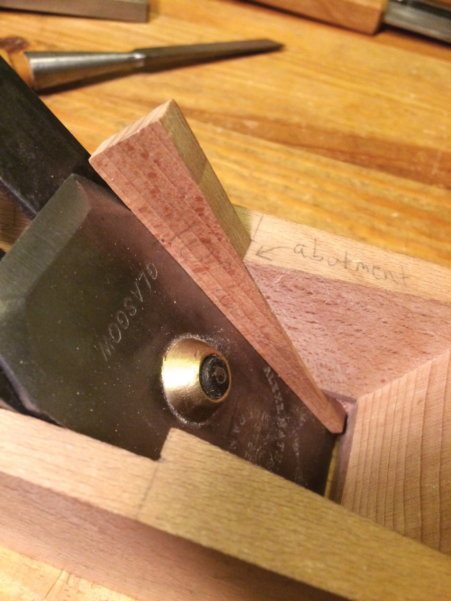
The next pair of cuts defines the abutments. The foolproof way is to first make a 9° wedge to guide your saw. It should be about 5⁄16” thick at the bottom, 7⁄8” thick at the top and just wide enough to fit into the rough mortise. In order to leave both hands free while cutting, press-fit the wedge into the mortise or apply a little spray adhesive onto its back to temporarily glue it to the bed. Afterward, a couple taps with a mallet will release it, and the spray adhesive will clean off easily with mineral spirits.
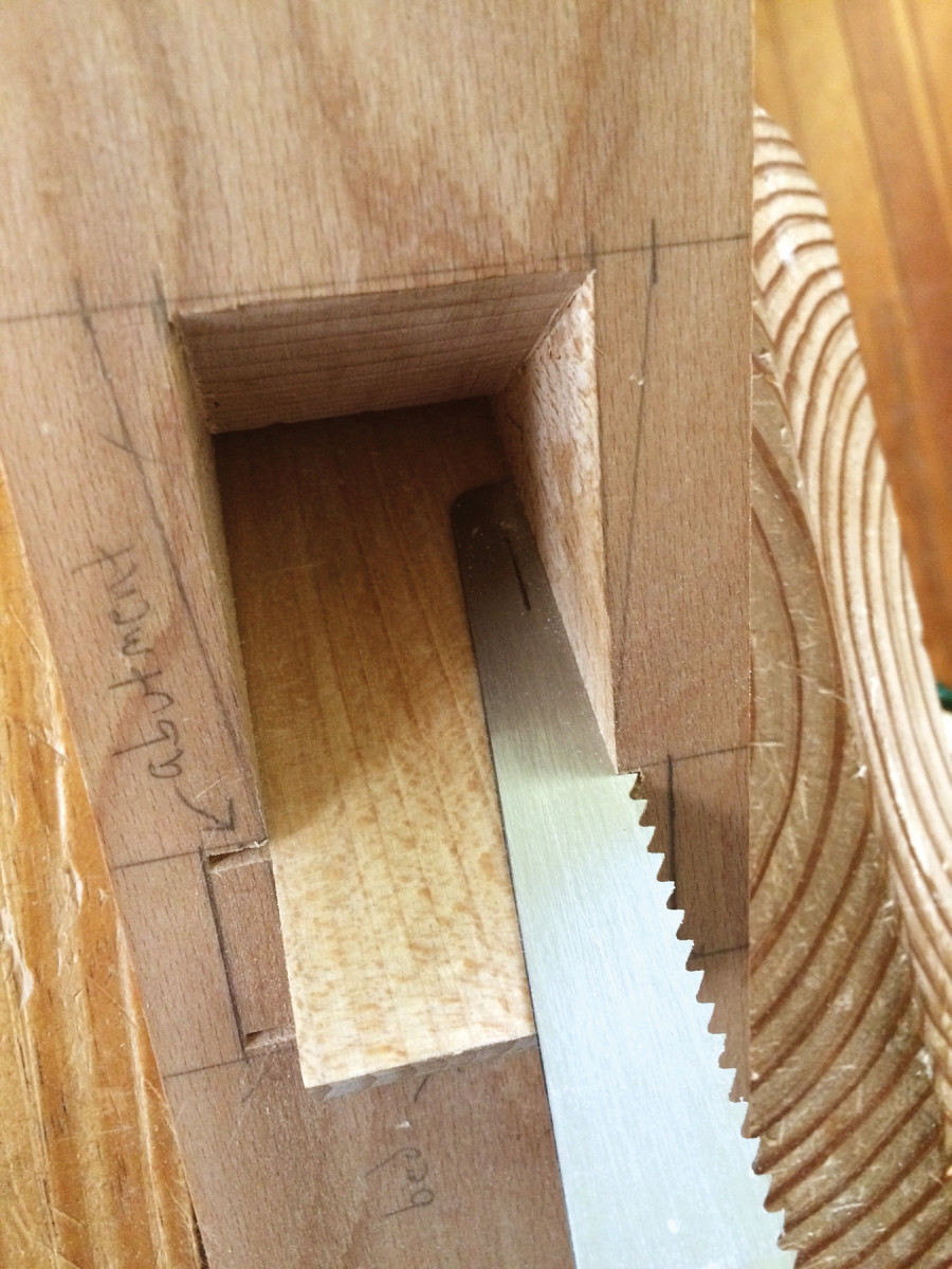
Saw guide. A guide wedge makes it easy to cut the other kerf for the abutments, and a line marked on the saw blade makes it easy to see how deep you’re cutting.
The abutment cuts are somewhat more difficult because they are stopped; you’re cutting right up to the wear. Go slow, use some wax on the saw blade and clean out the slot and saw teeth often.
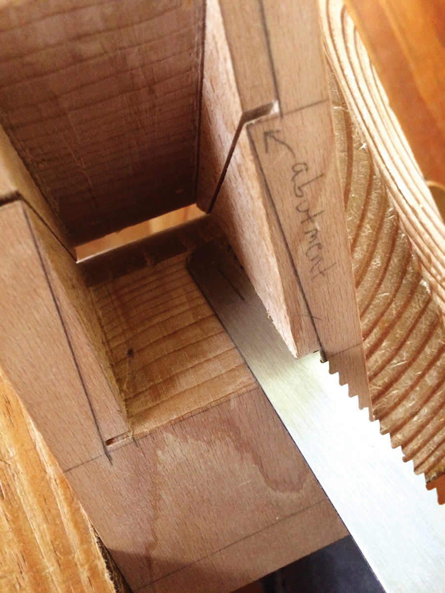
For the last pair of cuts, at the breast, hold the saw at an angle so that the teeth just graze the mortise wall at the top of the wear surface.
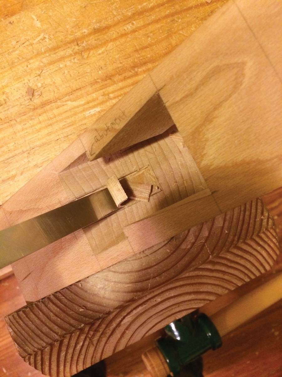
Next, use a chisel to knock out the waste between the bed and the abutments. Be aware of grain direction here; on one side (usually the right side) the waste will pop out easily, while on the other the chisel will want to dive below the surface of the cut. Take light cuts until you’ve determined which side you’re dealing with.
After you’ve pared away most of the waste, lay the edge float against the bed on one side and saw right to your layout lines. Then lay the float against the abutment on the same side and saw to the lines again. Remove the remaining island of waste with a side float if you have one; otherwise carefully chisel the waste away, or use overlapping strokes with the edge float. This method makes it easier to get a flat surface than going straight to the side float.
Breast cuts. The saw cuts at the breast lines are approximately 1⁄4″ deep at the top of the mortise, tapering to nothing at the top of the wear surface.
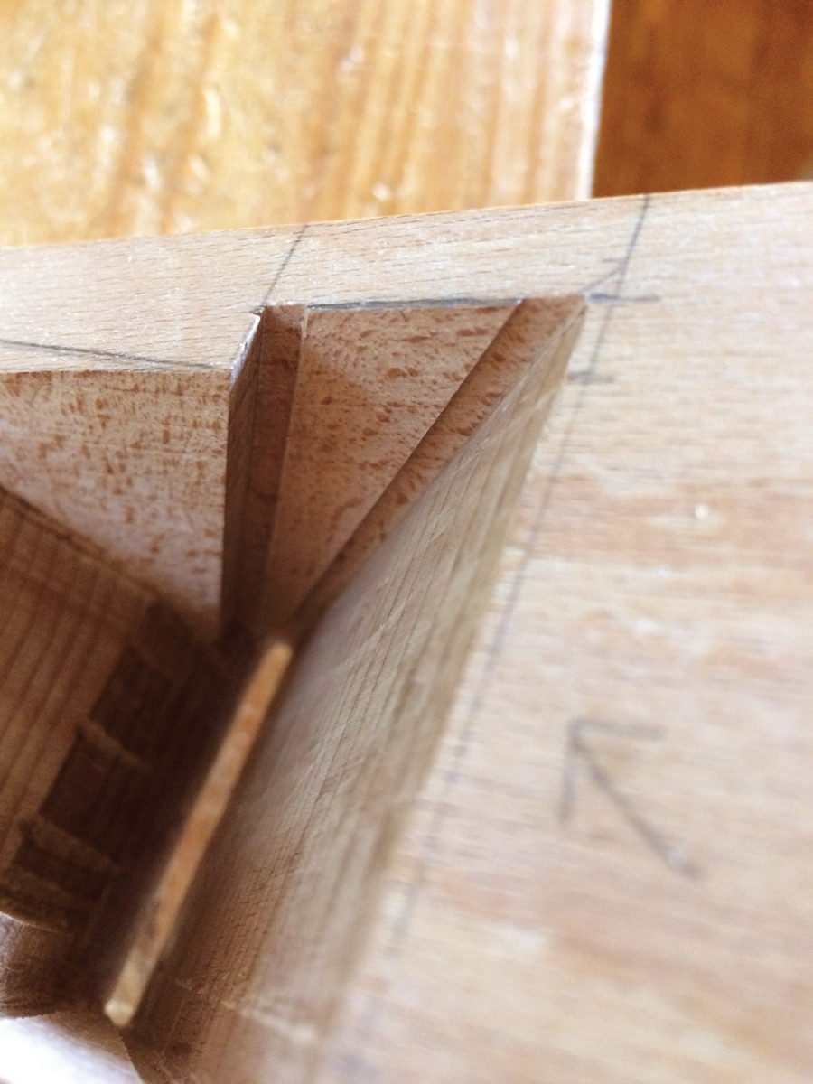
The next step is to define the escapement. If you have followed the directions so far, your abutments should be approximately 9⁄32” thick. In the finished escapement the abutments are 1⁄4” thick, and the front of the escapement is wider at the top than at the bottom; this helps shavings flow out of the escapement more easily. It follows that the cheeks are not in a flat plane. It’s a lot easier to cut this shape than to describe it.
Start by paring near the front of the escapement, angling the chisel to create the trapezoidal shape. Gradually work your way backward; when you’re almost to your layout lines, switch to cross-grain strokes to take the abutments to their final thickness. A 1⁄4” chisel held against the abutments makes a handy guide for assessing whether your abutments are the right thickness. Cut yourself a little slack here: If the abutments are bit thicker or thinner than 1⁄4“, or if they taper a little, it doesn’t matter – the plane will work just as well.
When you’re satisfied with the shape of the escapement, finish the bed and breast. Do the breast first – it’s almost inevitable that a few stray chisel strokes will slam into the bed while you’re working the breast. Because the precise angle of the breast is not as critical, just pare to your layout line with a chisel, then clean up with a float (or use the blunt chisel scraper).
Remove the island. Cut to the layout lines with the edge float, then chisel or float away the island in the middle.
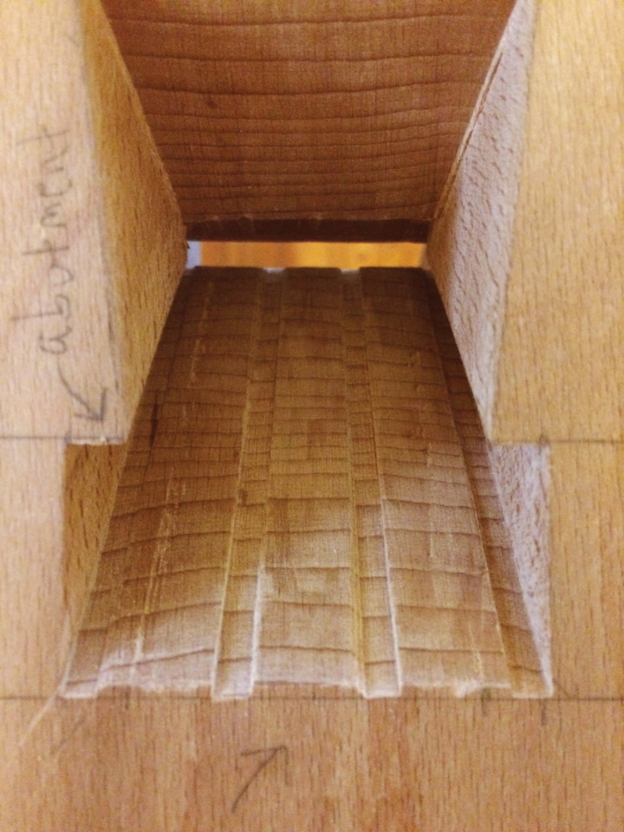
Finishing the bed calls for a different approach. Use your edge float and make three or four saw kerfs on the bed – two at the sides and one or two in the middle. These kerfs should just hit your layout lines on the top and sole. It’s critical that the float doesn’t rock up and down as you do this; the bottom of the kerf must be as flat as possible. When you’re done, chisel off most of the waste between the kerfs, then finish with either a bed float or the blunt chisel scraper.
Now sight down the bed to see if it’s twisted or has any obvious problems. Slide your cutting iron (without the cap iron) in as far as it will go (the mouth at this point should be too narrow for the cutting edge to protrude out of the sole). Check to see if the blade rocks. While holding the blade firm to the bed with one hand, try to slip an .001″ feeler gauge up through the mouth between the blade and bed, then try the same thing at the top of the plane. Correct any problems by floating or scraping away the high spots. If there are any problems, it’s actually easier to fix them now than when the slot is in the way.
Keep in mind that the bed doesn’t need to be perfectly flat; the cutting iron just needs to make good contact at the top and bottom of the mortise, so a little concavity in the middle is fine. What you don’t want is convexity or twist.
Float kerfs. An edge float makes it easier to cut a flat bed surface.
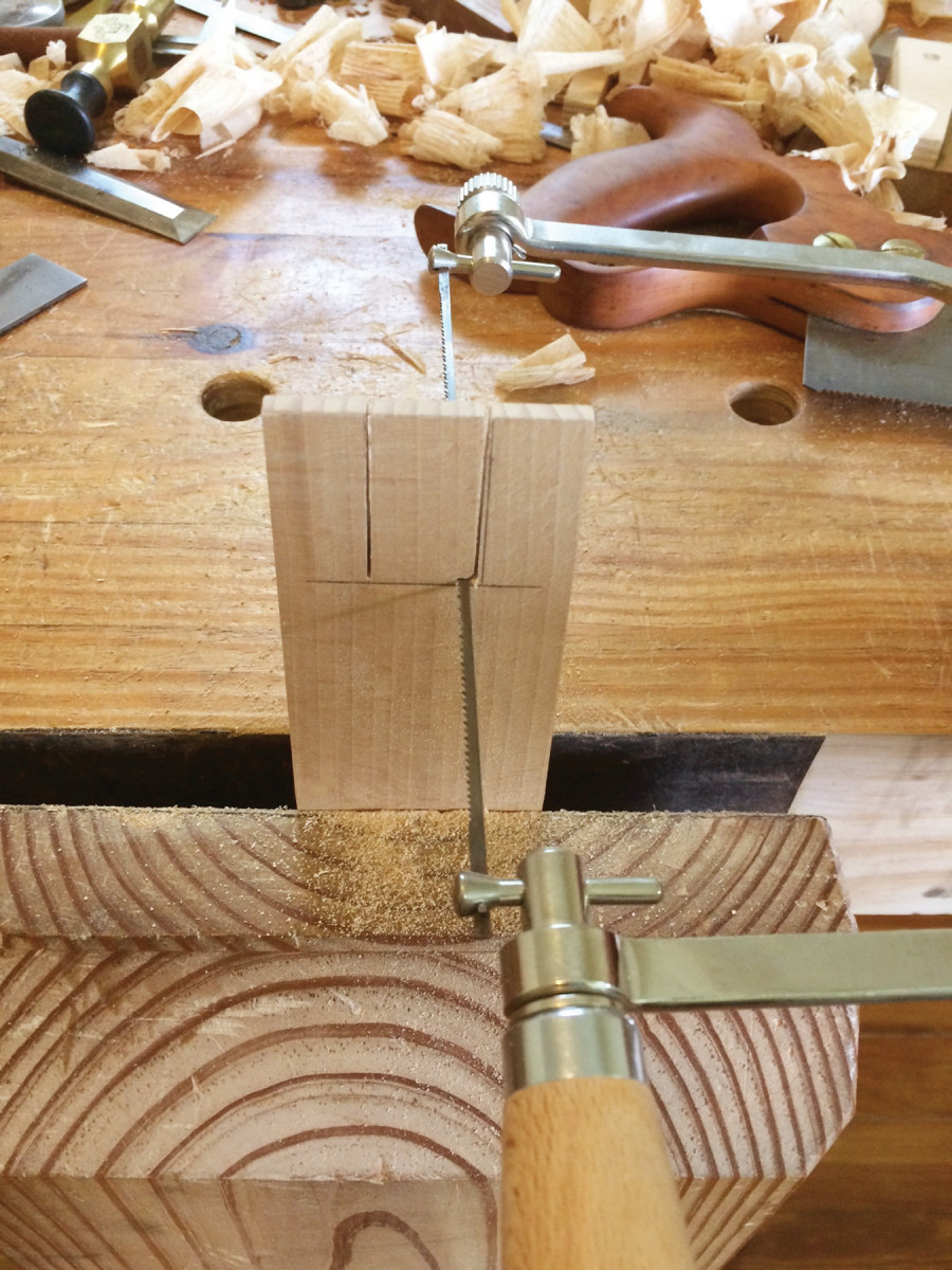
When the bed seems satisfactory, cut the slot for the cap-iron screw. The slot needs to be a generous 1⁄16” wider and deeper than the screw. It should be about 2″ long, but the precise length will depend on your cap iron. Just make sure the slot is long enough that the screw won’t bottom out when setting the iron for a heavy cut.
There are a couple of ways to cut the slot. If you have a drill press, you can hog out most of it with a Forstner bit, then finish with a chisel. If you’re without a drill press, use a backsaw to define the slot walls, leaving a little bit to pare away later (and don’t cut past the bottom of the slot).
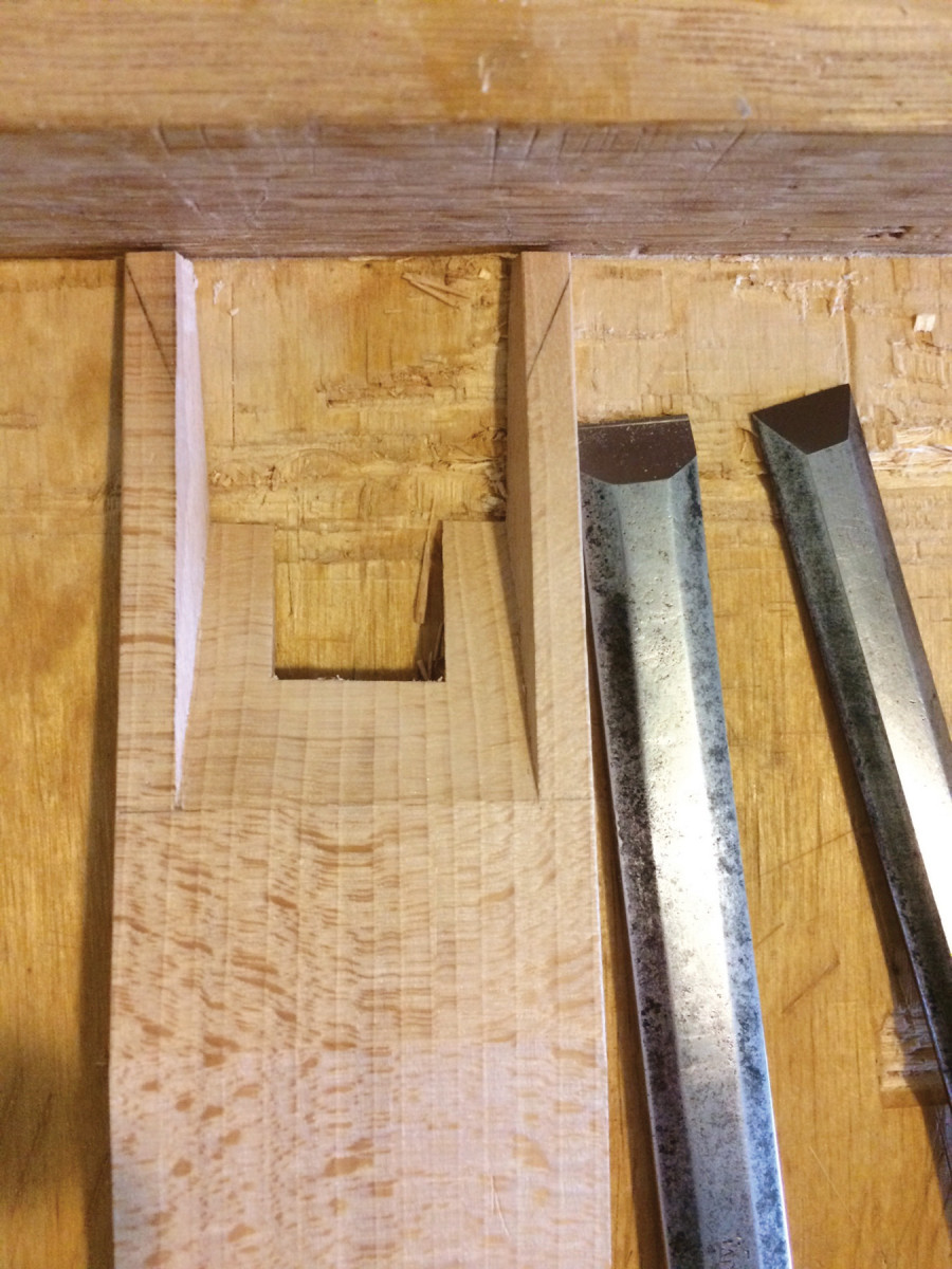
Slot cuts. These saw cuts are full depth at the top of the cap-iron slot and taper to nothing at the bottom – it’s a bit like cutting a half-blind dovetail, without overcutting it.
Define the bottom of the slot with a couple good whacks with the mallet on your chisel, then chop bevel down to take out most of the waste. Finish the slot by paring bevel up.
Next, finish the wear surface. The easiest way to do this is with a chisel and a paring guide. Take a piece of scrap about 2″ thick and cut an 85° angle on one end. Clamp it to your layout line at the front of the mouth. Make sure the block angles back toward the bed, not toward the breast. Then pare away. Aim for a mouth opening of about 1⁄64” – you’ll open it a bit more when you fine-tune the bed and flatten the sole.
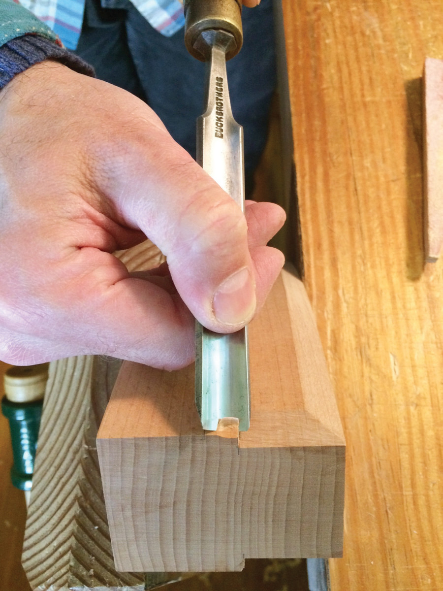
Defined walls. Sawing the sidewalls of the slot allows you to chop most of the waste aggressively, as I’m doing here, bevel down (which affords more control than bevel up).
The final step here is to taper the bottom of the abutments. This taper starts at the top of the wear and terminates about 1⁄16” above where the high point of the cap iron will be (usually 5⁄8” to 3⁄4” above the sole). Without this taper, shavings would run into the abutments and clog the mouth immediately. (If you’ve been wondering why the wear surface needs to be so tall, this is why.) For a clean mortise design, you want the abutment tapers to start at the top of the wear, and the taper angle to be gradual – somewhere between 20° and 30° – so that shavings will easily crumple as they squeeze between the wedge fingers and pass out of the escapement.
I cut the abutment tapers by holding the plane upright in a vise and nibbling away with a chisel held at approximately 25° off vertical and adjusting as necessary. I always chop with light, controlled taps to avoid driving the chisel into the mortise sides. Clean up any remnants by reaching through the mouth with a narrow chisel. Congratulations; you’re done with the mortise.
Abutment Tuning & Wedge
Mini-wedge. A narrow test wedge makes tuning the abutments a snap.
It’s important that the opening for the iron and wedge be symmetrical, otherwise the wedge will be lopsided, which can cause problems with adjustment. It’s easy to tune the abutments with a test wedge. Thickness a piece of scrap to 5⁄16” and cut out a 10° wedge. (Why 10°, and not 9° as I used earlier? The double iron has approximately 1° of taper.) With the plane on the bench, drop the assembled double iron in place and press the test wedge in on one side, finger tight. Make a pencil mark where the wedge meets the top of the plane, and repeat on the other side.
Now you know which side has the larger opening, so start on that side and use the mortise float to fine-tune the angle. A .001″ feeler gauge, slipped between the test wedge and the abutment, is useful for checking the angle. When you have the angle right, pencil another mark to indicate the depth of the opening, then tune the other side until the angle and depth match.
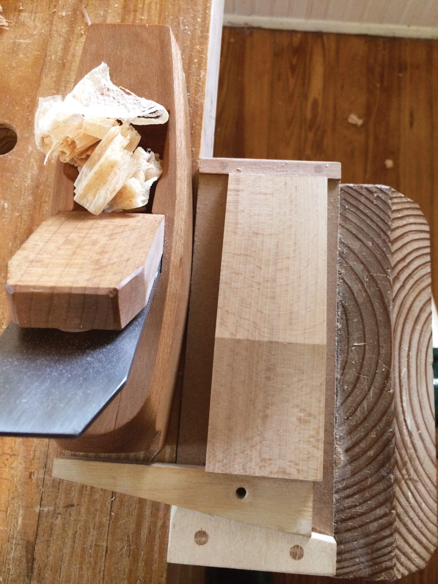
Wedge support. A simple fixture keeps the wedge from flexing while you’re planing it.
Now for the wedge. Take your test wedge and make a mark 1″ above your previous mark (at the point where the test wedge meets the top of the plane). This gives you the thickness of your wedge blank. The blank should be flat and square, and just wide enough that one end will begin to fit into the mouth.
To lay out the primary 10° angle, use your test wedge (boy, that thing comes in handy) to scribe the angle on one side. Carry the line across to the other side with a square, then scribe the angle with the test wedge again.
For production planemaking, I use a table saw jig to cut the angle, but if you are just making one, sawing by hand is faster and safer. I saw this angle the way Robert Wearing saws a tenon: Make a shallow kerf across the end grain, then saw on a diagonal on both sides, and finish up by sawing straight down.
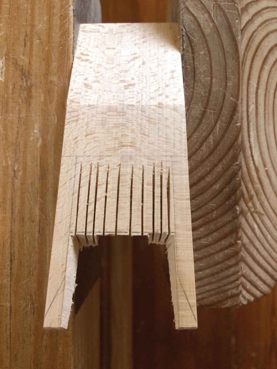
Slot cutting. Start by cutting a bunch of kerfs then pare the waste.
Next, plane down to your lines with a small smoother or block plane. If you hold the wedge in a vise, the bottom will flex a little because it’s thin, so I prefer to hold the wedge blank in a support fixture like the one shown at left. Alternatively, you can clamp or screw the top of the wedge to something (right now your wedge blank should be 1⁄2” to 1″ longer than its final length).
Finish the slot so it’s deep enough to clear the cap iron nut.
At this point, your plan of attack will vary depending upon what type of cap iron you have. If yours doesn’t have a nut protruding from the top (lucky you), proceed directly to the section on bedding the iron. If you do have a nut, you’ll need to make a slot for it. Start by cutting a notch out of the bottom of the wedge that is about 11⁄8” long and a fat 1⁄16” wider than the cap iron nut. This will leave two “fingers” about 5⁄8” wide. These will eventually be trimmed to about 1⁄4” wide, but leaving them fat now will make them easier to plane.
Next, lay the wedge on top of the cap iron and determine the length of the slot. It needs to be long enough to allow the wedge fingers to reach the high point of the cap iron plus about 1⁄4“. On this plane, the slot is 23⁄4“. Mark the slot on the back of the wedge, and mark its depth at the bottom of the notch you just cut (5⁄16” here). Kerf, then pare the slot as shown below.
Any time you are paring toward the fragile bottom end of the slot, support the other side on a bench hook or piece of scrap – but don’t worry if you get a little blowout; it should disappear when you cut the secondary ramp.
With the slot finished, check the fit of the wedge. Push it in finger tight and look for gaps at the abutments. If there are huge gaps, plane the wedge until it fits better, but don’t try to get a perfect fit at this stage. You’ll need to do some bedding first.
Traditionally, either oil or candle soot is used as a transfer medium. I’ve used oil, but now I prefer a modern alternative: dry erase marker. Rub the beveled side of the iron with the marker in two places: just above the bevel, and where the iron will meet the top of the plane. Put the iron in the plane, tap the wedge in place, and tap the top of the iron a couple times to move it a bit. Now take the iron out and inspect the bed.
Two saws. Make the vertical cuts with a backsaw. Slide a coping saw down the kerf; move it back and forth while rotating your wrist. When you’re at 90°, commence cutting the horizontal.
Because the cutting iron is sprung by the cap iron into a convex shape, the contact areas will be small, but you want to see a thin line across the bottom of the bed, indicating continuous contact. You also want the iron to contact the top of the bed on both sides of the cap iron slot. If you have uneven contact, use the blunt chisel scraper or a bed float to scrape away the high spots. Reapply dry erase marker and repeat the process until the iron is properly bedded.
Next, fit the back of the wedge to the iron using a similar approach. Rub dry erase marker on the bottom of the cap iron (above the curved part) and below the top edges. Tap the wedge into place, then remove the iron and inspect. You want to see dry erase ink on the bottom of both wedge fingers. Remember that the wedge fingers will finish at 1⁄4” wide, so you don’t need contact all the way across. You also want good contact at the top of the cap iron. The most common problem at this stage is that only one side at the top of the cap iron will be contacting the wedge, probably because either the cap iron or the wedge has a very slight twist. Fix this problem before moving on, or the wedge will not fit properly. Plane or scrape away the ink and repeat until you’re satisfied.
Now fit the wedge fingers to the abutments. Plane the fingers until you can’t see any gaps. Then try sliding a .001″ feeler gauge between the wedge and the abutments. Once the gauge won’t fit anywhere, inspect the fingers for burnish marks from the abutments. These can be tough to see, so use raking light.
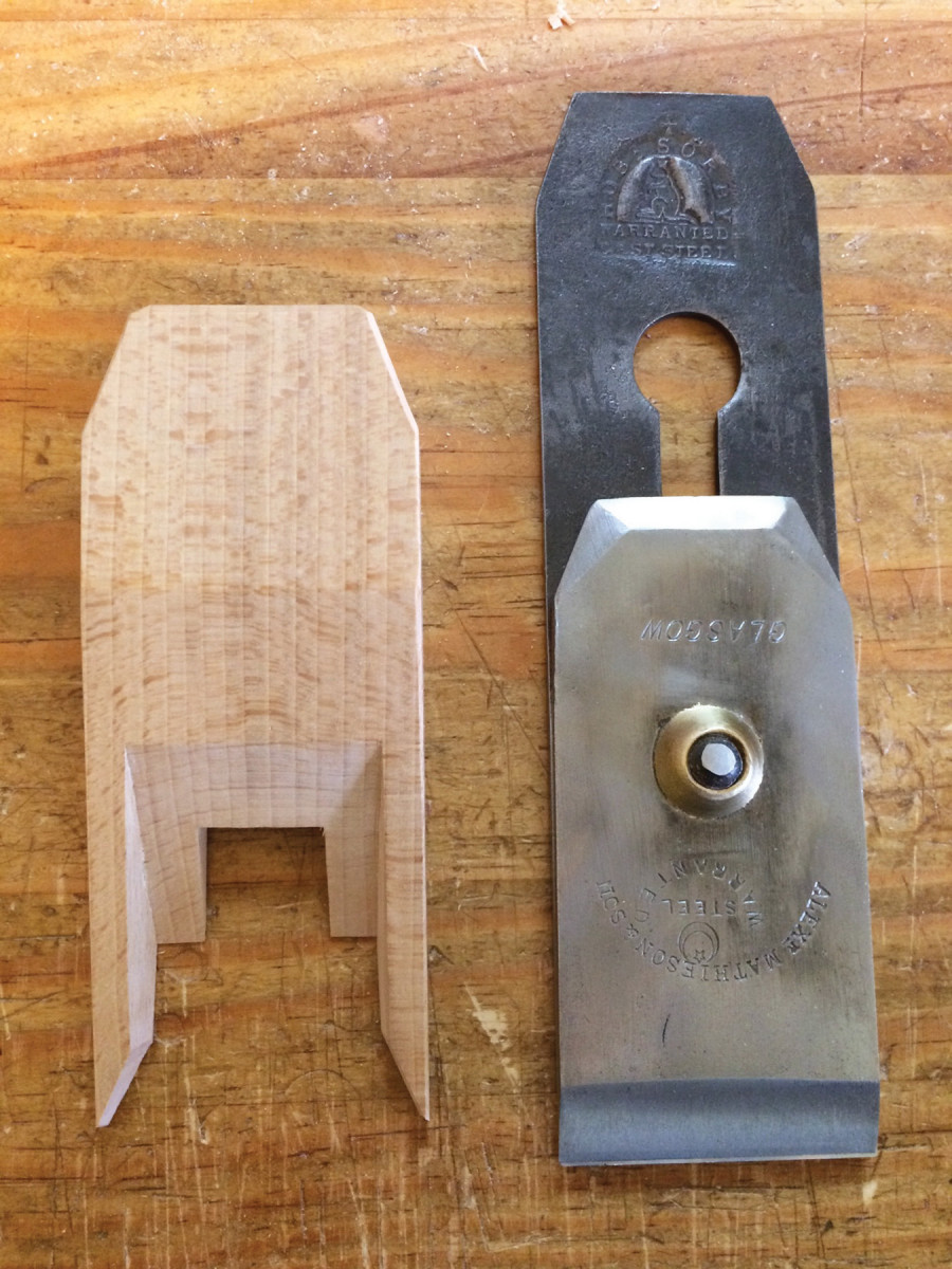
Wedge layout. Here are the wedge fingers and secondary ramp laid out. If your cap iron is nutless, you won’t have the notch pictured here.
If you don’t see anything, try reinstalling the wedge several times, seating it firmly with a mallet; the abutments will slightly compress the wedge fingers and help you see the burnish marks more clearly. Plane or scrape the burnish marks away; repeat until you can see that both abutments are making even contact with the wedge.
When you’re satisfied, tap the wedge in firmly one more time, then trace the outline of the abutments onto the wedge. Mark a line across the top of the wedge where it meets the top of the plane. Measure the distance from that line to the wedge tips, divide that distance in half, then mark another line across the wedge, between the fingers. This line marks the bottom of the secondary ramp, which helps sweep shavings over the cap iron and out of the plane. Finally, extend the full width of the fingers down to the bottom of the wedge. This will provide a place to start the saw cut for the fingers.
At an angle. When cutting out the fingers, angle your saw toward the center of the wedge.
Next, use a backsaw to cut the fingers down to the line that marks the bottom of the secondary ramp. When doing this, angle the saw about 15° (the exact angle isn’t critical) so that the fingers will be fatter on the bottom than on the top. This angle, like every other angle inside the escapement, is designed to help evacuate shavings more efficiently; it may also help to distribute force from the wedge to the cap iron more evenly.
Don’t cut the tapers yet at the ends of the fingers; leave them a full 1⁄4” wide all the way down. Those tapers are fragile, and you don’t want them to get beat up during subsequent operations.
Now it’s time to form the secondary ramp. Once again, pick up your backsaw and make a series of kerf cuts from the bottom of the secondary ramp to just shy of the line that marks the top of the plane. Then pare the remaining waste with your chisel. If you have a slot for the cap iron nut, the secondary ramp will cut into this slot. Cut carefully around the slot so you don’t get too much blowout.
Kerf-cut the secondary ramp. If you have a slot for the cap iron nut, the kerf cuts will break through the slot.
Now pare the fingers to your layout lines, then install the wedge and check your work. The insides of the fingers should fit flush with the cheeks; if they don’t, pare them until they do. Remember to follow the angle of your saw cuts so that the fingers remain fatter on the bottom than on the top. When the fingers look good, clean up the secondary ramp with the blunt chisel scraper. Then finish the fingers by paring away the tips until they match the tapers at the ends of the abutments.
Before you cut the wedge to length, take a look at the where the main ramp meets the upper portion of the wedge. There should be a sharp arris that is roughly 1″ above and parallel to the top of the plane. The distance is unimportant, but if it’s not parallel it may look a little funny. You can fix this if necessary by planing the top portion of the wedge until it looks right.
Now cut the top of the wedge to length so that there is approximately 11⁄2” between the top of the iron and the top of the wedge. Add side bevels adjacent to the top of the wedge. It looks nice if the angle of the bevels matches the bevels on the iron. Chamfer the edges of top of the wedge and you’re ready to move on to finishing the body.
Body Shaping & Details
Form the secondary ramp. I butt the wedge fingers up against the back of my bench hook, pare with a chisel (left), then finish with a blunt chisel scraper (right). The only downside is that this is hard on the bench hook.
Surprisingly, there is no standard shape for a coffin smoother. Nearly all examples I have seen share three general features: They are widest in the middle; they are narrower at the heel than at the toe; and there is some rounding of the heel. Within these parameters, designs vary widely.
The shape I use is nearly symmetrical, has restrained curves and a heavily sculpted heel. At the other extreme, a Victorian-era Mathieson plane I own has an exaggerated teardrop shape, with minimal rounding of the heel. Take your pick between these options, or design your own.
Matched bevels. A nice aesthetic touch for the top of the wedge are bevels that echo those on your iron.
Once you’ve got a design you like, trace it onto the top of the plane and start cutting. If you don’t have a band saw, don’t try to cut the curve; just make four straight cuts with a handsaw to define the sides, then use shaping tools (drawknife, spokeshave, plane) to define the shape.
I refine the shape by light traversing cuts with a plane using (don’t forget to chamfer the far side to avoid spelching), then fair the curves with a bed float and clean up with a card scraper.
Like the shape of the plane, the chamfers and gouge cuts vary widely on historical examples. Planes from the 18th century have crisp flat chamfers and well-defined gouge cuts, while later planes have more rounded-over edges and indistinct gouge cuts.
Stop. I use a 11⁄4″-tall stop-block to achieve chamfer cuts of a consistent depth.
Start by laying out the chamfers. Set a combination square for 5⁄32” and scribe six lines across the top and down the heel and toe. Change the setting to 3⁄8” and scribe six more lines below the top and down the sides. There’s nothing magical about these numbers – I like a slope of a little more than 2:1, but anything from 2:1 to 3:1 will look fine.
Most planemakers cut the long chamfers first, but I have always started with the stopped chamfers. Do whatever makes sense to you. Cut the stopped chamfers with a chisel, and use a stop-block to keep from cutting too deeply.
Cutting the long chamfers cleanly can be tricky due to the curved surface. I use a high-angle spokeshave followed by a gunstock scraper. Before I had those tools, I used a small plane and a file. No matter the tools, take light cuts, work down hill and stay true to your lines.
When the chamfers are done, make the gouge cuts below the stopped chamfers. I use a gouge with a radius of slightly more than 1⁄4“, which gives a stylish undercut; however, a larger radius is more common, and is easier to cut.
Nice eyes. The eyes make it easy to reach into the escapement without chafing your fingers.
A nice 18th-century detail is to leave a fillet (roughly 1⁄32“to 1⁄16“) above the gouge cut, but many old planes lack this fillet. Again, it’s a matter of taste. These touches – while nice – are non-functional.
Next, lay out and carve the eyes (the teardrop shapes in front of the abutments). A quarter is handy for marking the radius. I carve the eyes with a Sloyd knife, but a chisel or shallow (No. 2 or No. 3 sweep) gouge will work.
The final detail is to round the heel. As with the other details, the heel shape can vary quite a bit. I like a sculpted heel that is a stylized interpretation of an early 19th-century design. However, many old smoothers have a pretty perfunctory rounding – just enough to keep the plane from being uncomfortable in use. The important thing is to choose a design that pleases your eye and feels comfortable in your hand.
Sole, Tune & Finish
Details. The gouge cuts are a visually pleasing way to terminate the stopped chamfers, and a small fillet left above the gouge cut is a nice touch.
The final step in the build is to flatten the sole. Install the iron so that the cutting edge is about 1⁄16” above the sole. Tap the wedge in firmly, pencil some witness marks across the sole, and abrade it on some sandpaper stuck down to a flat surface. Once the sole is flat, check the mouth opening.
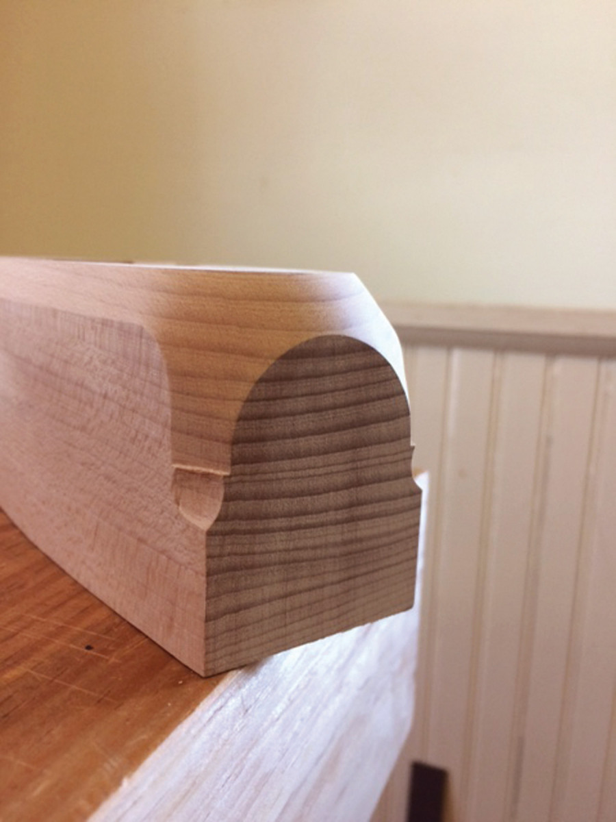
A rounded heel is comfortable in the hand.
With the iron set for a shallow cut, the mouth should be about 1⁄32“. If it’s wider, no problem; a double-iron plane depends upon the cap iron to control tear-out, so mouth size is mostly a cosmetic issue. If it’s not wide enough, grab the paring block you used earlier and pare the wear a bit. Then sharpen the iron and take your plane for a test drive.
Just about any oil finish will make your plane look great: Watco Danish Oil, Minwax Antique Oil Finish and Tru-Oil Gun Stock Finish are all popular among planemakers. I avoid using finishes that have a lot of varnish in them inside the mortise. A coat of wax will protect the outside of the plane, but don’t get any wax on any of the mating surfaces inside the mortise.
Here are some supplies and tools we find essential in our everyday work around the shop. We may receive a commission from sales referred by our links; however, we have carefully selected these products for their usefulness and quality.