


We may receive a commission when you use our affiliate links. However, this does not impact our recommendations.

Build accurate replicas of a classic design
Having built the Mission oak dining table that appeared in American Woodworker (Dec/Jan 2009, issue 139), my next project was to build chairs to go with it. A friend had a vintage set that I admired, and she graciously loaned me a couple chairs (one with arms, one without) to inspect and measure. These chairs were classic Mission style, and although they were a bit small by today’s standards, they were still comfortable to sit in. I was excited to find labels identifying their manufacturer as the Stickley Brothers Company, because according to the magazine article, the table I had built was also based on a Stickley Brothers design.
I did some research, using Stickley Brothers Quaint Furniture catalog reproductions. Tables and chairs were most often pictured independently, but in one catalog, I found these chairs, identified as #379-1/2, facing the table that I had just built. That was it; these were the right chairs for my table.
Including an arm chair as part of a set is optional (see more on that below), so in this story, I’ll focus on building the side chairs. At first glance, these chairs look pretty simple to build, thanks in part to their rectilinear style. But closer inspection reveals subtle details that make them a challenging project. Of course, they’re made out of quartersawn white oak, with the quartered faces presented on the chairs’ fronts and backsides.

Photo 1. This chair assembles primarily with loose tenon joinery, which is a variation of traditional mortise and tenon joinery. This method simplifies the complex joints between the legs and rails.
I couldn’t disassemble the chairs I’d been given, so I made thoughtful choices about the construction techniques I would use. Most of the joints are fitted with loose tenons (Photo 1). In addition to creating strong joints, loose tenon joinery is versatile—a major consideration, as each chair requires several types of mortise-and-tenon joints. All of the loose tenon mortises are routed with a simple shop-made jig (Fig. A). I decided to use traditional mortises and tenons to assemble the curved rails and back slats.
Cutlist and Diagrams


Fig. A: Mortising Jig

Fig. B: Exploded View

Fig. C: Back Leg

Fig. D: Side View

Fig. E: Front View: Back Assembly

Fig. F: Front View: Front Assembly

Fig. G: Crest Rail


Make the front and back legs
- Cut lumber for the back legs to rough size (Part A, Fig. B and Cutting List).
- Make a full size pattern for the back legs (Fig. C). Trace the profile onto a blank, nesting the second leg behind the first.

Photo 2. Saw out the back legs. To get the most from your lumber, nest them together. Remove saw marks by sanding, scraping or planing to the layout lines.
- Carefully cut the legs on the band saw (Photo 2). Use scrapers, planes or a sander to remove the waste.
- Cut the front legs (B) to final dimensions.
- Clamp the front and back legs to each other in pairs to lay out the mortises (Photo 3 and Figs. D, E and F). All of the seat rail mortises and lower mortises are centered on the leg faces. Note that the seat rail mortises are 3/8″ wide. All the other mortises are 1/4″ wide. Whenever possible, orient the legs so the mortises will be cut on their least attractive faces. Use a square to transfer the mortise locations to the correct leg faces.
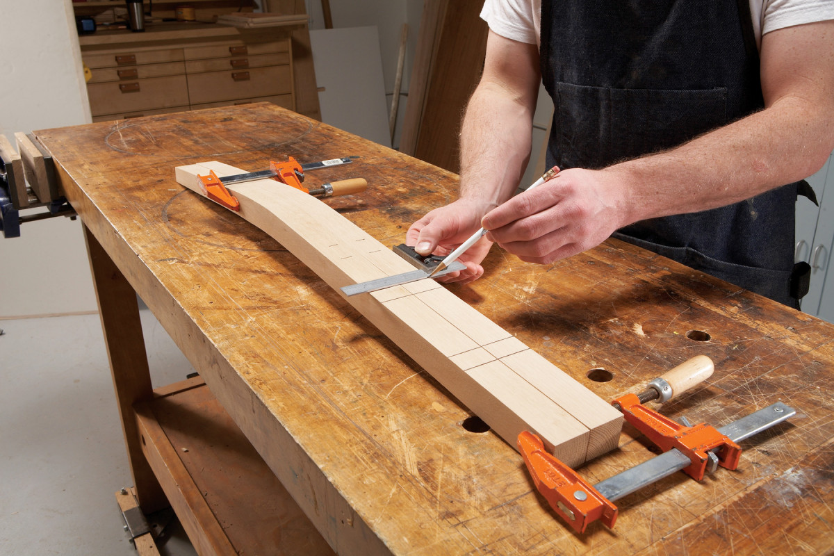
Photo 3. Lay out the side rail mortises on the back legs. Clamp the legs together so the mortises are perfectly parallel. Use a square to transfer the back rail mortises to the legs’ inside faces.
- Mark the back legs for the crest rail and lumbar rail mortises (Figs. C and E). These mortises are not centered on the leg faces and they run at a skewed angle. They must be in the same plane for the back assembly to fit properly. To determine this plane, you must line up two points on the side of the leg; one at the top edge of the lumbar rail 1/4″ in from the edge, and the other at the top edge of the crest rail 1/8″ from the edge. Draw a straight line between the two points and align the crest and lumbar rail mortises with this line.
- Start by routing all the 3/8″ mortises for the seat rails, then rout all the 1/4″ mortises—it’s easier to mount leg pieces in the mortising jig than it is to change router bits.
- Set up to rout the leg mortises. Clamp the mortising jig to your bench. Attach an edge guide to your router and install a 3/8″ spiral bit. During operation, the router rides on top of the jig; it’s base straddles the sides’ edges and the edge guide bears against one side. Lay out a mortise on a test piece that’s the same size as a front leg. Clamp this piece against the side of the jig and flush with its top. Then make test cuts to center the mortise and set the depth. Adjust the edge guide to center the mortise; adjust the plunge mechanism to set the depth. Rout to the layout lines to establish the length.
- Install each front leg and rout 1″ deep mortises for the front and side seat rails (Photo 4). Start by plunging 1/8″ deep; complete each mortise by making incrementally deeper passes.
- Install each back leg and rout 1″ deep mortises for the side and back seat rails. For the side seat rails, clamp the legs against the side of the jig and flush with its top, the same way you clamped the front legs in Step 6.
- Set up to rout the lower rail mortises. Install a 1/4″ spiral bit in the router and adjust the plunge depth to 7/8″. Don’t change the edge guide set-up; these mortises are also centered.

Photo 5. The mortises for the crest and lumbar rails are skewed, rather than parallel to the front face of the back legs. To skew these mortises, install a wedge between the leg and the edge of the jig. Measure to ensure the mortises are coplanar.
- Rout mortises for the all the lower rails in the front and back legs (Figs. D and F).
- Mortise the back legs for the lumbar and crest rails. These mortises run at an angle, so use wedges to hold the legs in the correct position (Photo 5). Once the leg is wedged in position, adjust the edge guide to properly locate the mortises.
Assemble the front and back
- Cut the front seat rail (C) and front lower rail (D) to final dimensions. Make a pattern to shape the lower rail (Fig. G). Cut the curves on the band saw and smooth the edges.
- Cut the back seat rail (E) and back lower rail (F) to final dimensions. Cut blanks for the crest rail (G), lumbar rail (H) and back slats (J) to final length.
- Make a pattern (Fig. G) to transfer the curved shapes of the crest rail and lumbar rail onto the blanks. Mark the ends of these blanks, too, so you can locate the mortises, which are offset, rather than centered. These mortises are located 1/8″ from the back face, so they won’t cut through the curved front face.

Photo 6. Rout offset mortises in the ends of the crest and lumbar rail blanks. Draw on the rails’ curved shape, so you can locate the mortises. Clamp the blank vertically, so it’s end is flush with the jig’s top.
- Rout 1/4″ x 7/8″ deep mortises in both ends of the crest rail and lumbar rail blanks (Photo 6).
- Rout 1/4″ x 7/8″ deep mortises in both ends of the back lower rail. Mount this rail in the jig vertically, the same way the crest and lumbar rail blanks were mounted.
- Change bits and rout 3/8″ x 1″ deep mortises in both ends of the front seat rail, the front lower rail, and the back seat rail.
Mill loose tenons (K and L) to fit the 1/4″ and 3/8″ mortises. Plane lengths of stock to appropriate thickness and rip them to width. Then use your router table and a 1/8″ roundover bit to round the edges of the 1/4″ stock. Make two passes, one on each face. Round the 3/8″ stock, using a 3/16″ bit. Use a pull saw to cut individual loose tenons from each length of stock. The tenons for the seat rails are mitered on one end. I make my 1/4″ tenons about 3/16″ undersize in width. This allows some adjustability when I’m assembling the chair; it’s especially helpful for fitting the compound miters between the side rails and back legs.
- Assemble the front legs and rails without glue, to check the fit and alignment of the joints. Do the same with the back legs and rails.

Photo 7. Saw out the crest rail in two steps. First saw out the bowed faces. Then reattach the offcuts to saw the curved top and bottom edges.
- Bandsaw the bow-shaped crest and lumbar rails from the blanks (Photo 7). Reattach the crest rail offcuts with tape; then bandsaw the crest rail’s curved top and bottom profiles.

Photo 8. Chop mortises for the back slats in the crest and lumbar rails. Drill out the centers, then use chisels to remove the waste and square the corners.
- Mark the mortise locations for the back slats on the crest and lumbar rails (Fig. G). Use the offcuts from sawing to securely clamp these bow-shaped rails in a vise. Then chop the 3/16″ x 1/4″ deep mortises (Photo 8).
- Mill 3/16″ x 1/4″ tenons on the back slats on the tablesaw, using a tenoning jig and a handsaw (Photo 9).
- Assemble the slats and curved rails to test the fit. Then assemble the entire chair back to check the fit.

Photo 9. Use a tenoning jig to cut tenons on the back slats. Shave a small amount off both faces of each slat, to create the cheeks. Then use a handsaw to cut the shoulders.
- Finish sand all the parts and ease the edges—I use a laminate trimmer equipped with 3/32″ roundover bit for this job.

Photo 10. Glue the back of the chair together. Make sure all the joints are square, and measure diagonally to ensure the assembly is square. Follow the same procedure to glue the front assembly.
- Glue the entire back leg assembly on a flat surface (Photo 10).
- Glue the front assembly the same way.
Make the Side Rails
- The chair seat is wider at the front than the back (Fig. H), and the legs are slightly canted (Fig. D). This makes the chair more comfortable and stable, but it also means that the rails on the sides of the chair are mirrored parts with compound angles. A dual-compound miter saw is the best tool for making these angled, mirror-image cuts. To avoid mistakes, I keep all the rails (M, N and P) positioned as if they were in the chair while I measure, mark and cut the ends. (Photo 11).

Photo 11. To measure and mark the side rail blanks, orient them as if you were standing behind the chair. This keeps all of the important angles facing the correct direction for cutting on the miter saw.
- Cut all of the front ends first (Photo 12). These are simple 83˚ miter cuts.
- Mark the outside top length of each rail. This length increases with each successively lower part (Fig. D). At the mark, draw a 97˚ miter across the top edge of each rail and a 92˚ bevel on each outside face.

Photo 12. Cut the ends of the all the side rails. The front ends are simply mitered, but the back end angles are both mitered and beveled. A dual-compound miter saw handles this operation with ease.
- At the line, cut compound 97˚/92˚ miters on the back end of all the side rails.
- Mark mortise positions on the ends of all of the rails.
- To align with the leg mortises, the rail mortises have to be perpendicular to the angled faces of the ends of the rails. Make an 7˚ wedge to mount a seat rail in the jig—the same wedge works for both ends, because the angles are complementary (Photo 13). The end of the rail should be just above the top of the jig.

Photo 13. Use a tacked-on wedge to position the side rails for mortising. The wedge levels the rail’s mitered face across the top of the jig, so the mortise will align with the corresponding leg mortise.
- Gently tap the end until the face is perfectly flush with the top of the jig (Photo 14). Double-check with a square laid across the ends of the jig. Then tighten the clamp firmly.
- Install the 3/8″ spiral bit into the router. Set the fence and bit for correct location and depth. Rout 1″ deep mortises for loose tenons into each end of both side seat rails.

Photo 14. Lightly tap the clamped rail with a mallet, to level its face with the jig from end to end. This two-step method works to position both ends of the rails—mitered and compound mitered—for mortising.
- Replace the bit with a 1/4″ spiral bit. Then follow the same procedure to rout 1/4″ x 7/8″ mortises in the remaining side rails.
- Finish sand all of the side rails and ease the edges.
Assembly
- Assemble the entire chair without glue to test the fit. Use a sliding bevel square to make sure the angles of the side seat rails match. You may have to finesse a few joints by shaving or trimming the tenons, so the chair clamps up even and square.
- Once you’ve fine-tuned the fit, disassemble the chair and glue it together (Photo 15).

Photo 15. Glue the chair together. Use a sliding bevel square to make sure both sides widen at the same angle.
- Cut angled front and rear corner blocks for the chair (Q and R). Orient the grain to run lengthwise on the blocks. Drill countersunk shank holes for screws.
- Clamp the corner block in place temporarily, 3/8″ below the top of the seat rails. Then use the shank holes to drill pilot holes into the seat rails. Remove the corner blocks, apply glue to the angled surfaces, and screw the blocks in place.
- Drill 3/8″ holes in the legs for the decorative dowel pegs (S). The pegs flank the crest rail, the front and back seat rail and the front and back lower rails. Apply glue to 3/8″ oak dowels and insert them into the holes. Remove any glue squeeze out. Saw or sand the pegs flush.
- Apply a finish. I used the same finish that I put on the table; developed by Kevin Southwick, it’s an authentic finish for white oak Arts and Crafts style furniture.
Upholster the Seat
You can bring the chairs to an upholstery shop, or you can upholster the seats yourself. My cost for covering the seats in leather came to about $60 per seat.
- Cut the seat frame (T) out of 1/2″ Baltic birch plywood (Fig. J). Center the seat on the chair. Reach under with a pencil and trace the position of the seat rails. Glue and nail a sub-frame (U), 1/8″ inside the line you’ve scribed around the bottom of the seat frame (Photo 16).

Photo 16. Glue and tack a sub-frame to the seat frame. The sub frame fits between the chair’s seat rails, so the seat frame partially overlays the top of the rails.
- Round over the top edge of the seat with a 1/4″ roundover bit.
- Staple webbing across the seat opening.
- Trace the outline of the seat on 1/2″ foam, 3/4″ larger than the seat. Using the bandsaw, cut to the lines at a 45˚ angle for a smooth transition around the edges of the seat (Photo 17).
- Lay the foam on a clean work surface, beveled side up. Spray adhesive onto it. Press the seat onto the adhesive-covered foam, upside-down and centered. Trim out the corners with a scissors.

Photo 17. Saw the foam that covers the seat frame at a 45˚ angle to create a tapered edge, so the seat makes a smooth transition from the top to the side.
- Lay muslin on the work surface. Lay the seat foam-top-down onto the muslin. Pull the muslin back over the edges and staple it to the seat bottom at the intersection of the seat and frame. Staple the sides first, then the back, and finally, the front. (Photo 18). Keep the muslin uniformly tight, but not so tight that it puckers.

Photo 18. Wrap muslin around the seat frame and staple it where the seat and the sub-frame meet. Carefully cut the muslin to wrap the corners. Repeat the process with the leather upholstery.
- To wrap the muslin at the corners, carefully slice it diagonally towards the center of the corner, and staple the flaps. Trim of the excess material with a utility knife.
- Repeat this process to install the upholstery material.
- Install the seat in the chair (Photo 19).

Photo 19. Install the completed seat. It’s a friction fit, so no screws are necessary.
- Press wood buttons into all of the screw holes with glue.
Bonus: Build The Chair with Arms
Vintage chair sets often included an armchair, usually a larger version of the side chairs. For this set, the part dimensions and rail angles of the armchair are different, but all the basic building steps are the same.


Here are some supplies and tools we find essential in our everyday work around the shop. We may receive a commission from sales referred by our links; however, we have carefully selected these products for their usefulness and quality.


