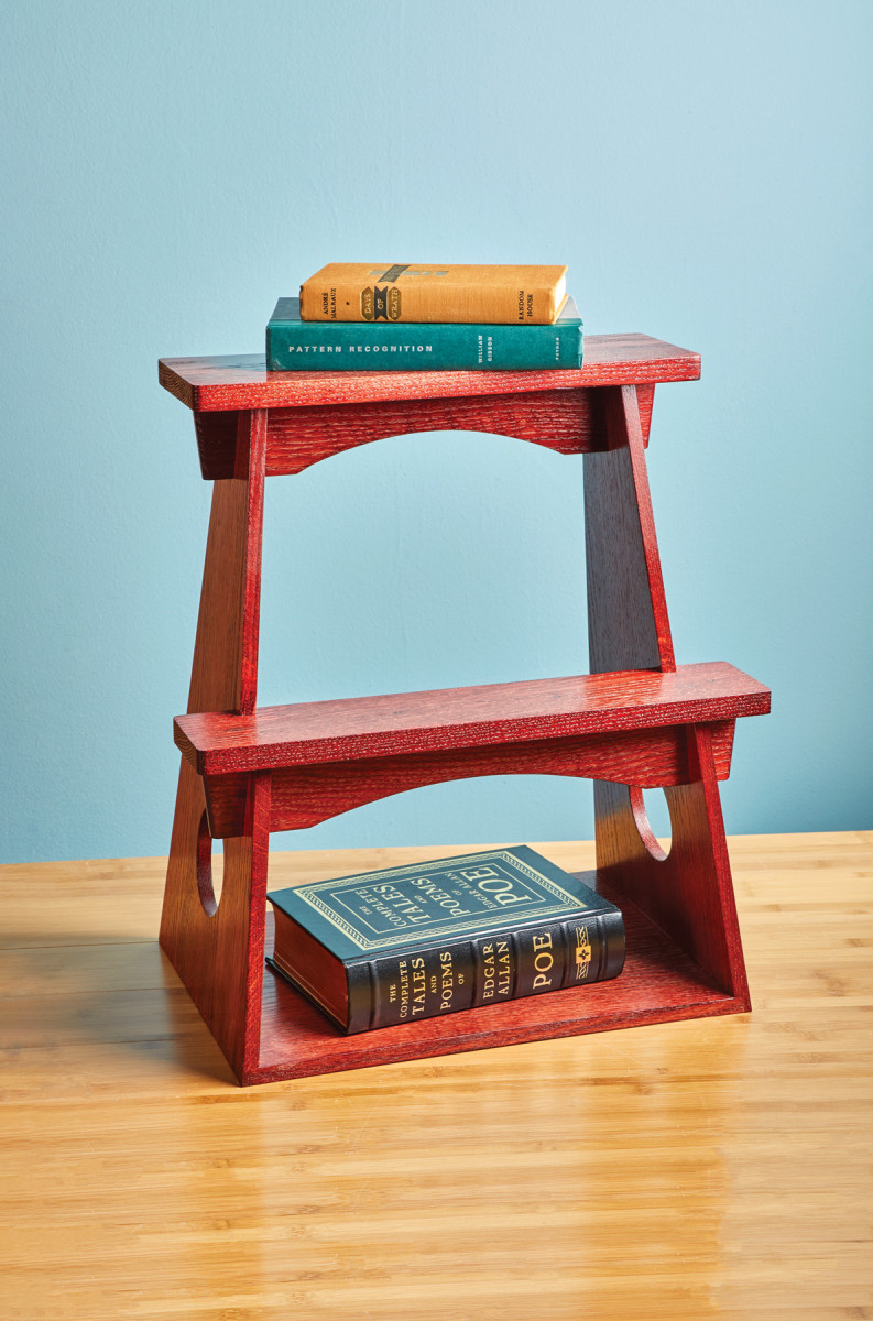
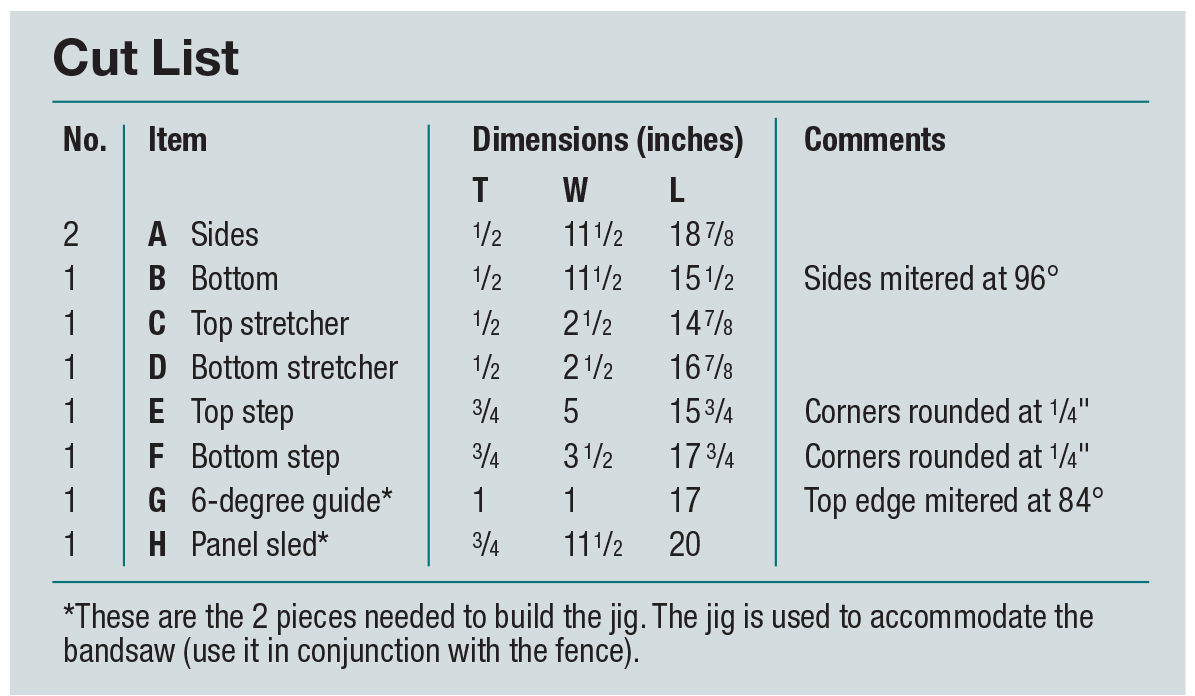
We may receive a commission when you use our affiliate links. However, this does not impact our recommendations.
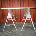
This intriguing utilitarian design is at home most anywhere.
As a curious designer I often find myself frequenting estate sales, online auctions and even local antique stores in search of oddities and relics of the past. This exercise affords me the opportunity to be exploratory in my quest for inspiration and has become a practice that remains integral in the overall design process. The act of seeking without presumption allows one to experience new pieces through an unadulterated lens. This method has also proven itself to be an effective way to develop a historical connection with pieces and to appreciate the zeitgeist of any given period.
It’s this exact process that led me to discover a set of 19th century Japanese street vendor stools on a British auction site. Initially frustrated by my inability to discover any sort of historical context or provenance for such a piece, my focus soon became directed towards its simple aesthetic and form. I instantly became drawn to the stool’s intimacy of scale/proportion. The angularity of their shape combined with a straightforward construction method made this not only an approachable project from a build perspective, but one that can easily be integrated into any space.
 Preparing the Panels
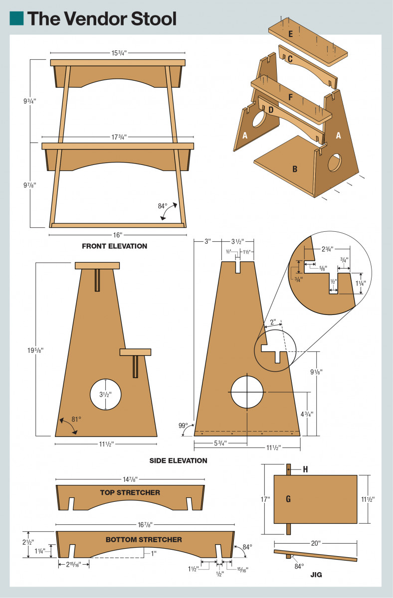
The first part of the process is to construct a 1/2“-thick panel that will become the two sides (A) as well as the bottom (B) of the stool. To save on time and ensure grain continuity, I constructed one large panel glue-up that exceeds the combined lengths of both sides as well as the bottom. Once the glue has dried, rip the panel to its final width as well crosscut your sides/bottom to their respected lengths (I did this all at the table saw). Once these three pieces are prepped, it’s time to start cutting the joinery.
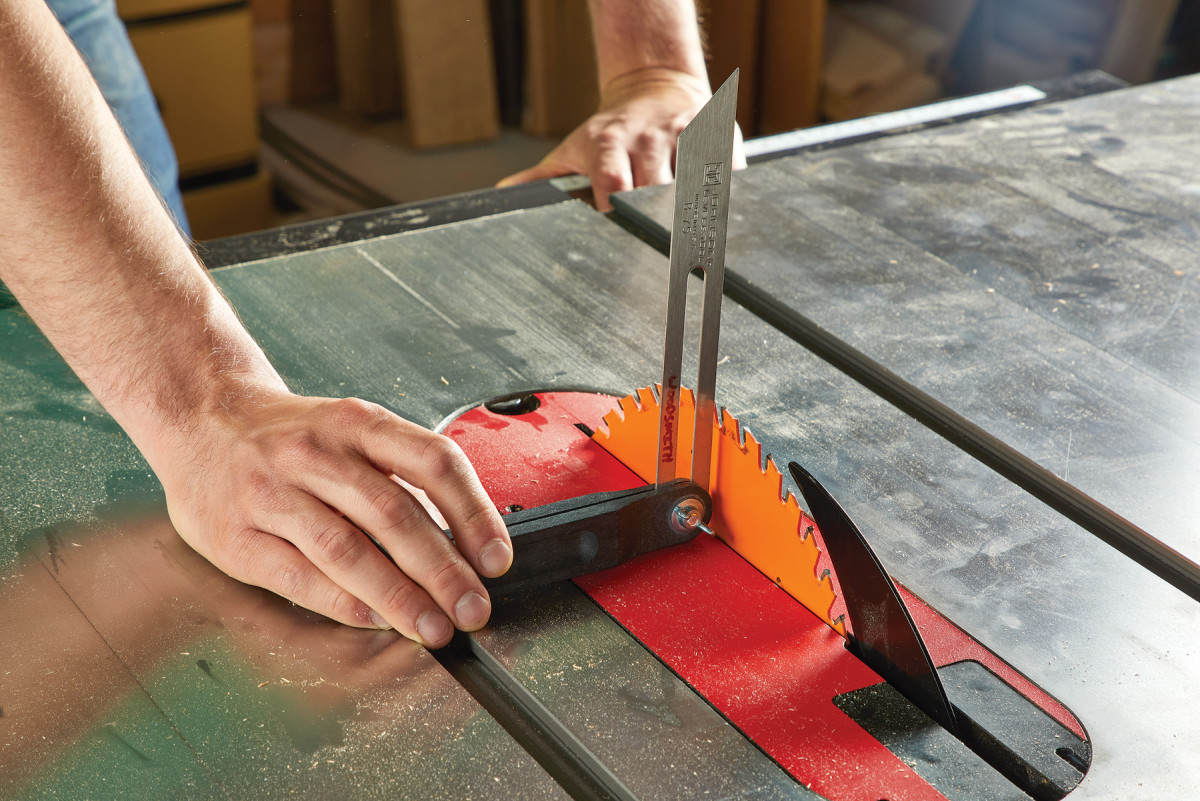
1. Set the bevel of your table saw blade to 6°. You’ll use this setting for multiple crosscuts and non-through cuts.
Angled Perspective
Since we are conveniently located at the table saw from panel preparation, proceed to set the blade to 6°. This setup will be used for several cuts on the project, however, at this time the only adjustment that will need to be made is at the fence. Start by moving the fence to accommodate the full length of your stool sides (A) or 19″. Move your fence over enough that the blade can complete the 6° angled cut required. Once you have made a pass at one end, flip your panel 180° on end and make the second cut. This should render your two cuts parallel to one another and at a 6° splay when placed perpendicular to a flat surface. Proceed to do this for both side panels.
2. Cut your side to length. Then, rotate and cut the other side. This will give you a panel with two ends cut at 6°. Repeat for the other side panel.
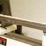
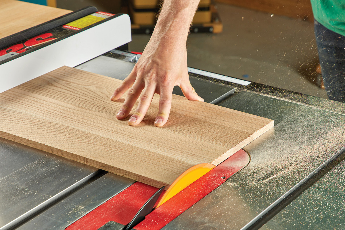
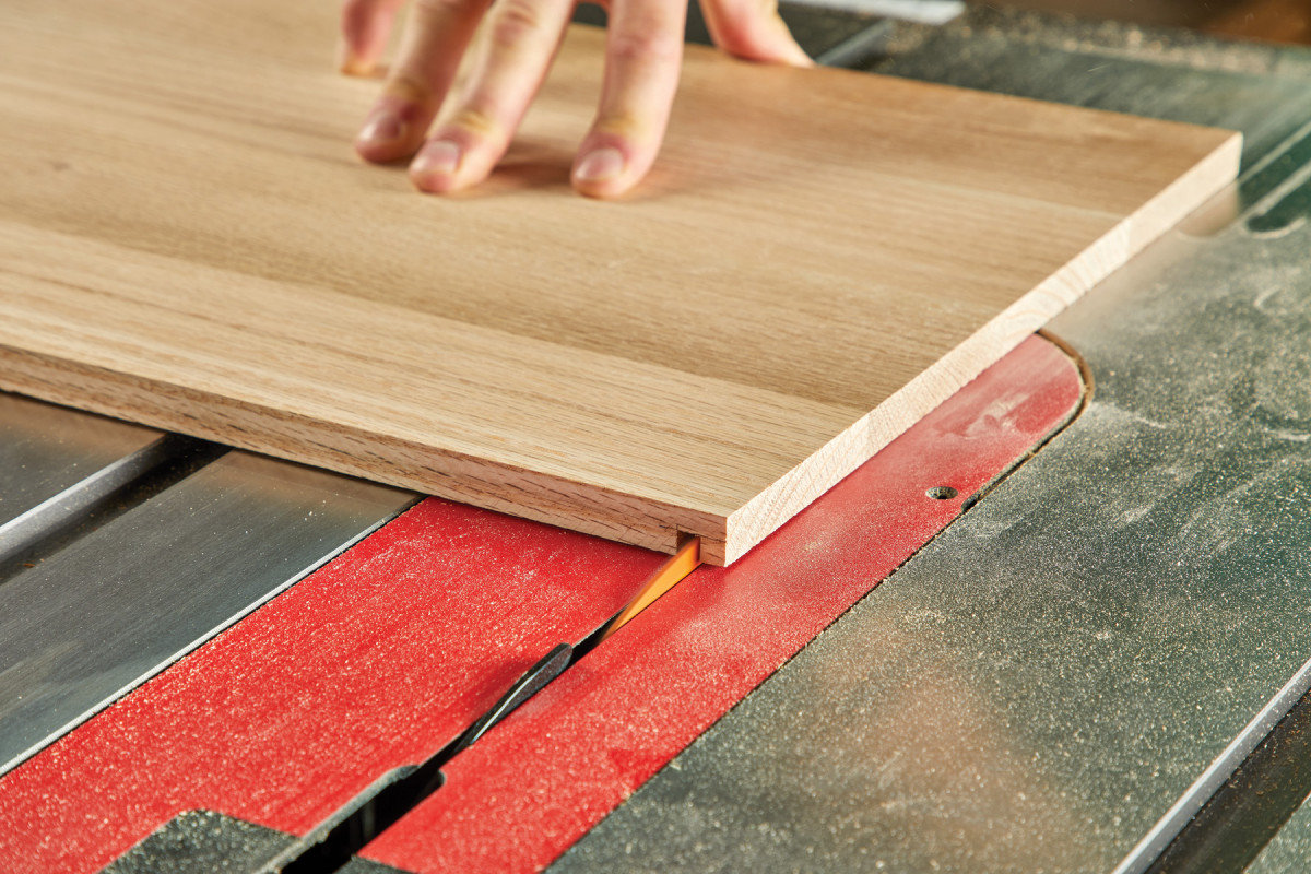
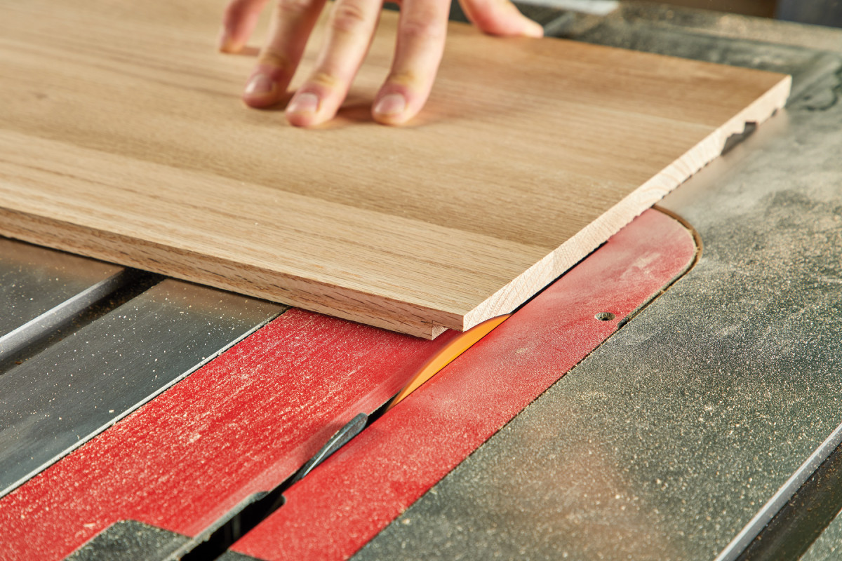
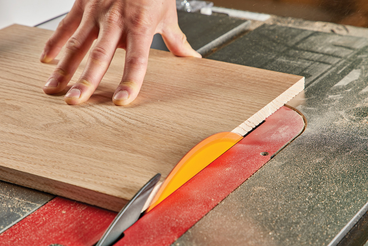
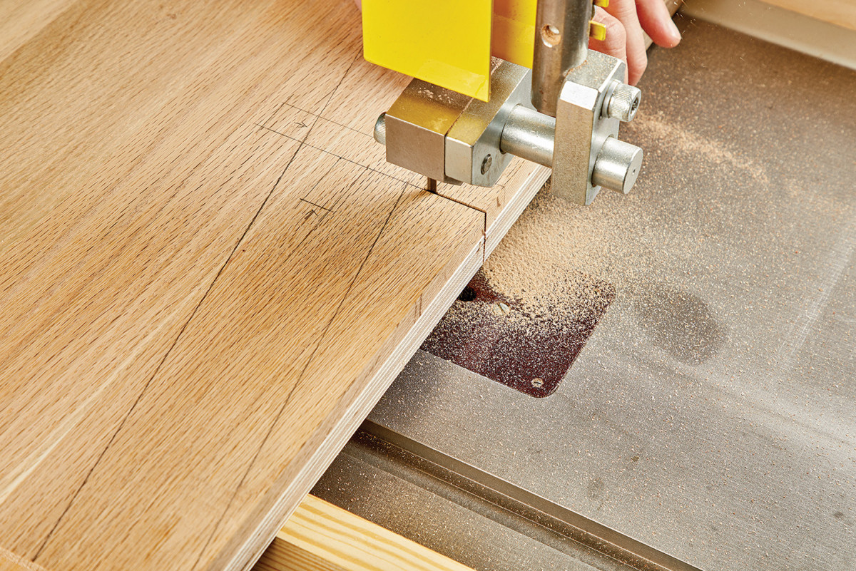
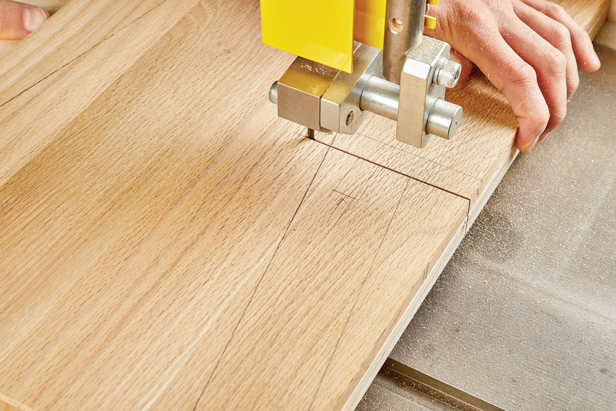
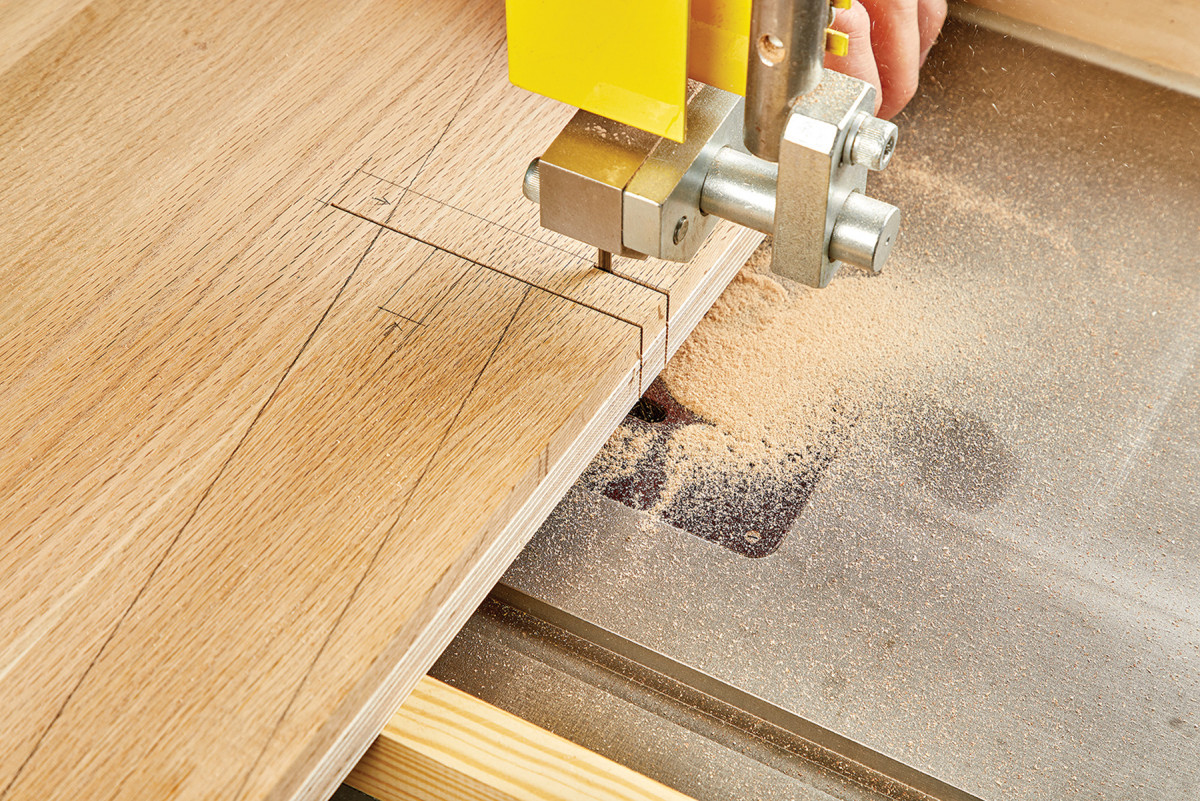
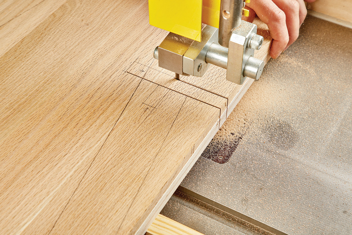
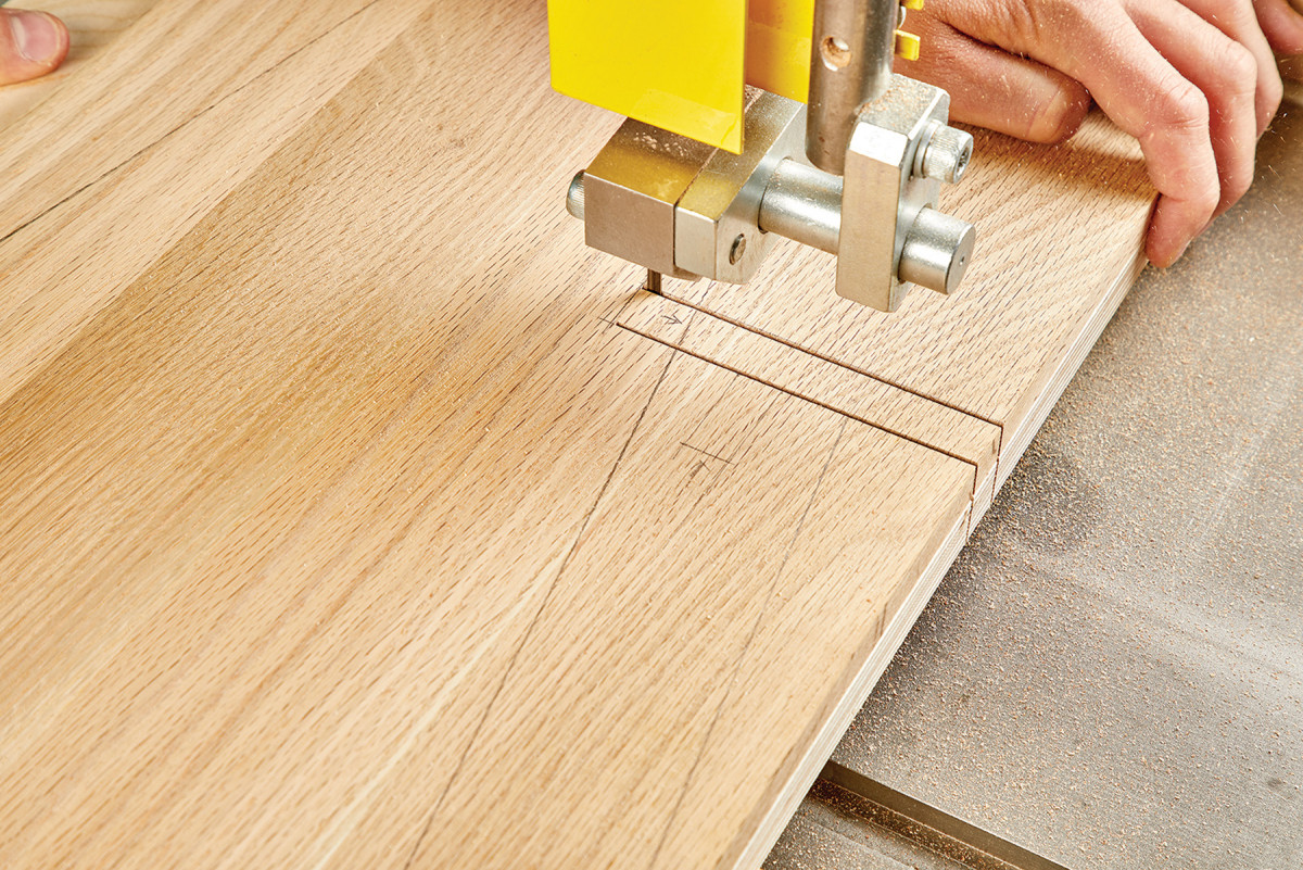
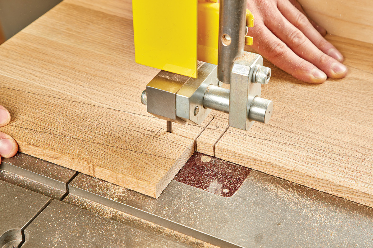
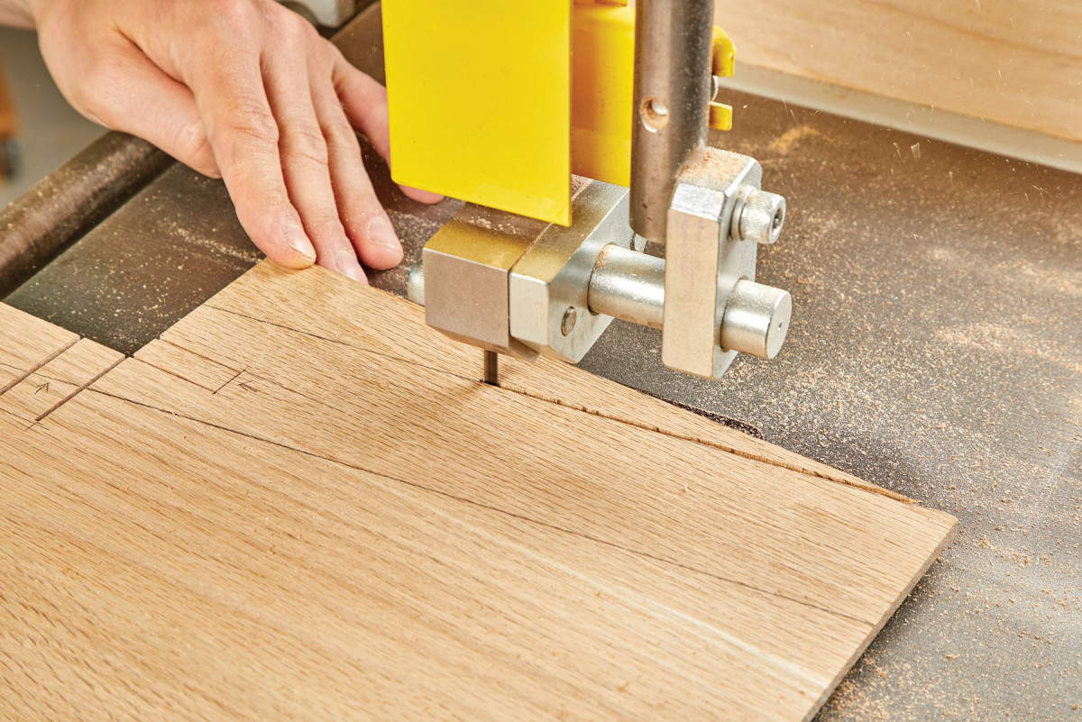
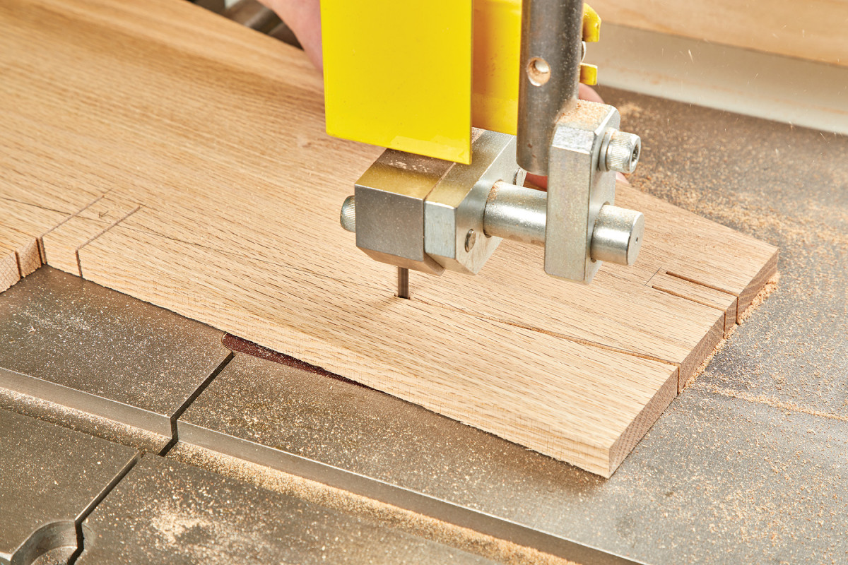
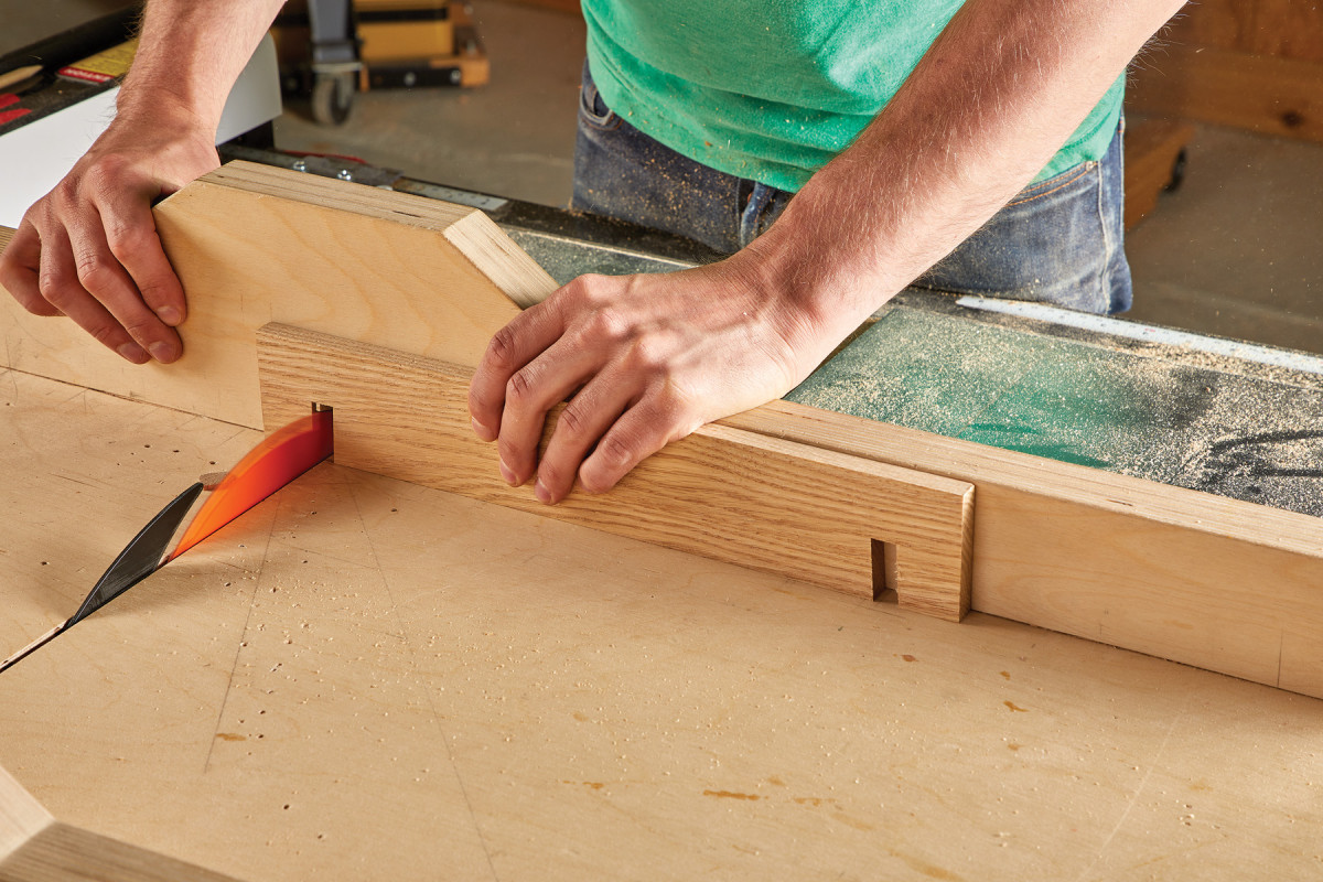
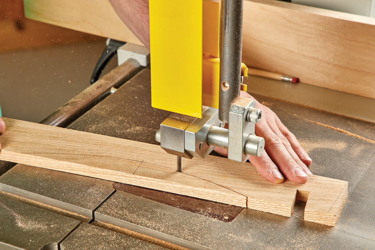
The next step is to cut the rabbets on one end of each panel. Layout the 1/2“ long by 1/4“ deep cut on the panel and lower the table saw blade to accommodate the 1/4“ depth. Using your fence, make the first cut to establish the shoulder of your rabbet. Since we are using the kerf of a single blade, continue to make a series of passes to create the cheek. Depending on the type of table saw blade being used (or have access to), you may notice that it has a tendency to leave a v-bottom kerf or even what’s referred to as “bat ears”. This can easily be remedied with a few passes of a router plane or a sanding block.
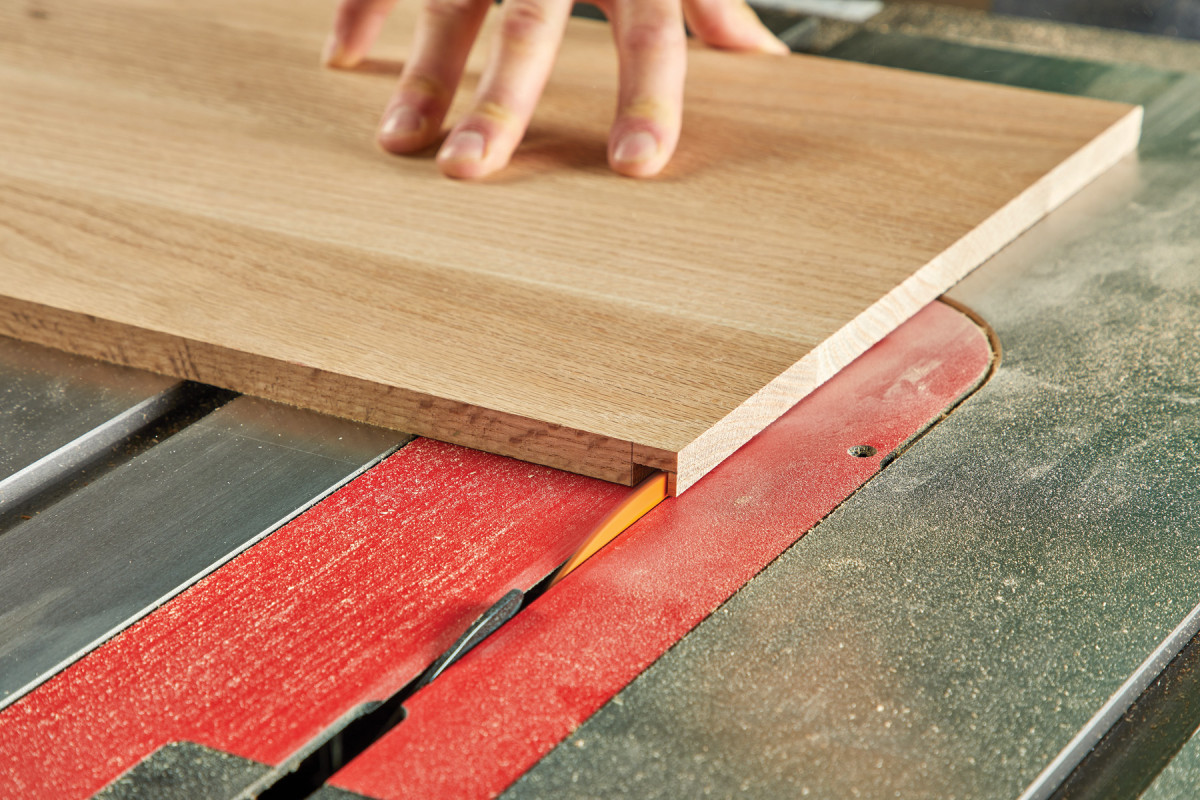
3-5. I use a single blade and take multiple passes to cut the rabbets. Start by defining the inside edge of the 1/2″ rabbet, then continue to cut away a blade width at a time.
4.
5.
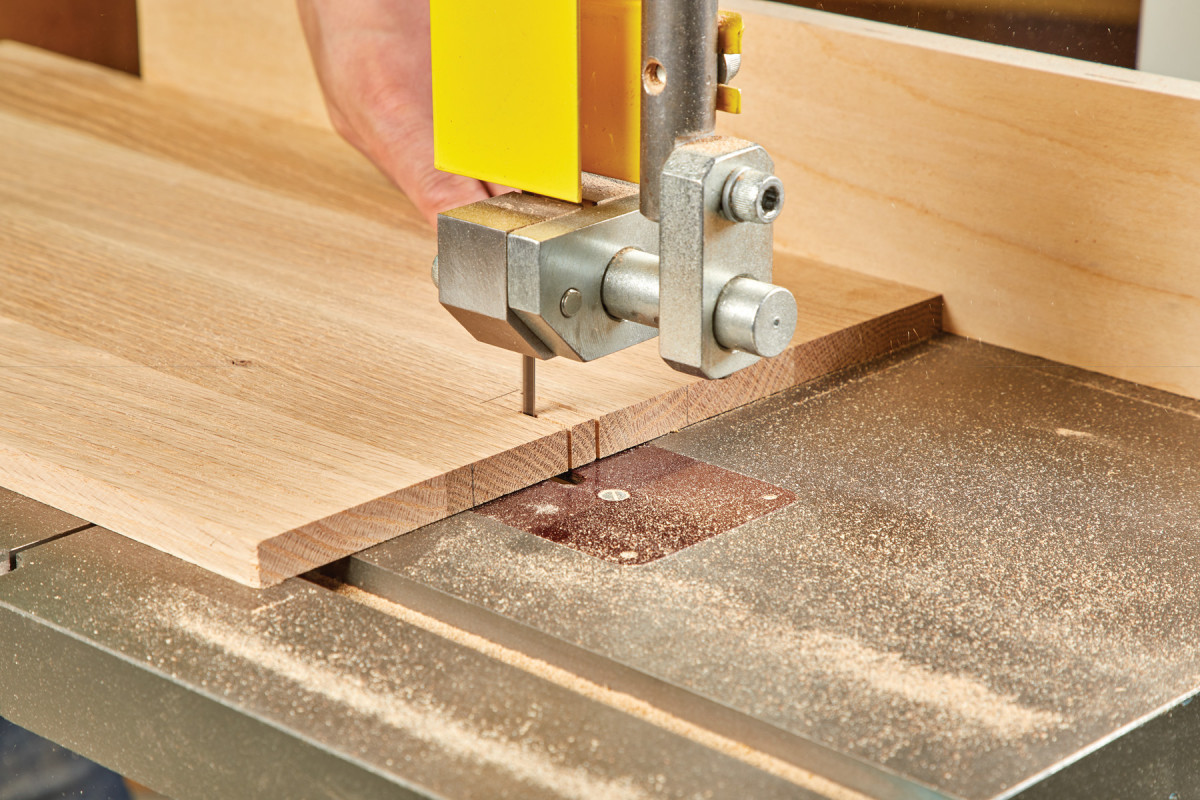
6. Once the rabbets are cut, adjust the blade to 9° and bevel the front and back edges of the bottom panel.
With the blade still at 6°, proceed to make cuts on both ends of the bottom panel (B) to accommodate the rabbet on the side panels. Then, tilt the blade another 3° to make 9° and flip the bottom panel 90° to make cuts that correspond with the angle of our two side panels.
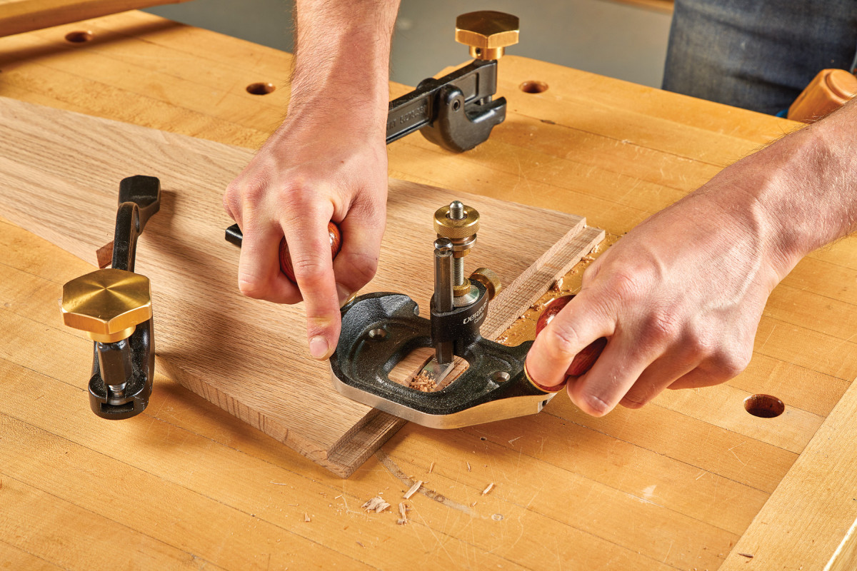
7. With all of the joinery cut for the two sides, I clean up the rabbets with a router plane (though a sanding block would also work).
Simple Motif
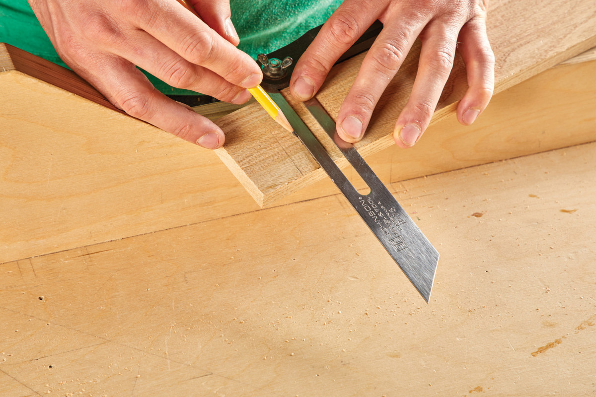
Find the middle of each panel (5 3/4“) at the bottom and measure 43/4“ up to establish a center point. From this point, using a compass, draw a circle with a 3 1/2“ diameter. To reduce the number of cuts along with ensuring accuracy, go ahead and adhere both panels together using carpet/double stick tape.
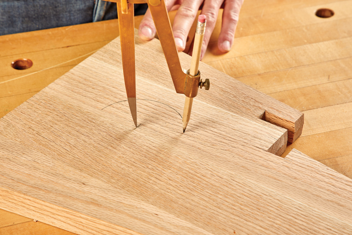
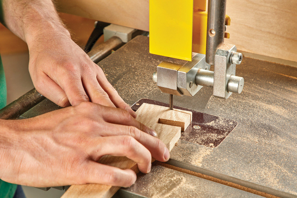
8. With a compass, lay out the 3 1/2″ circular cutouts on both of the stool sides (making sure to mirror the layout). Then cut them out with a jigsaw.
Drill a pilot hole anywhere within the desired diameter using a standard drill bit (one large enough to accommodate a jigsaw blade). Once this pilot or access point is complete you may proceed to rough cut your circle pattern using a jigsaw. These saws are inherently crude and will inevitably leave coarse blade marks behind. Clean up any remaining inconsistencies left with a spindle sander or a rasp.
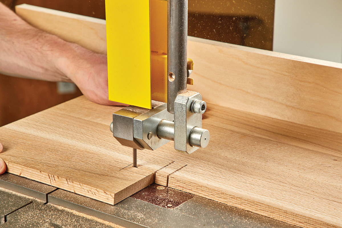
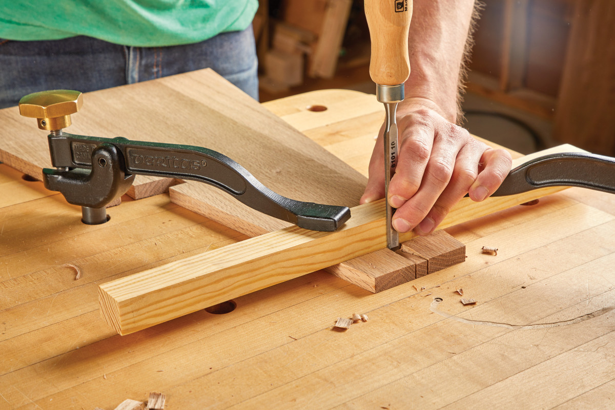
Power at Hand
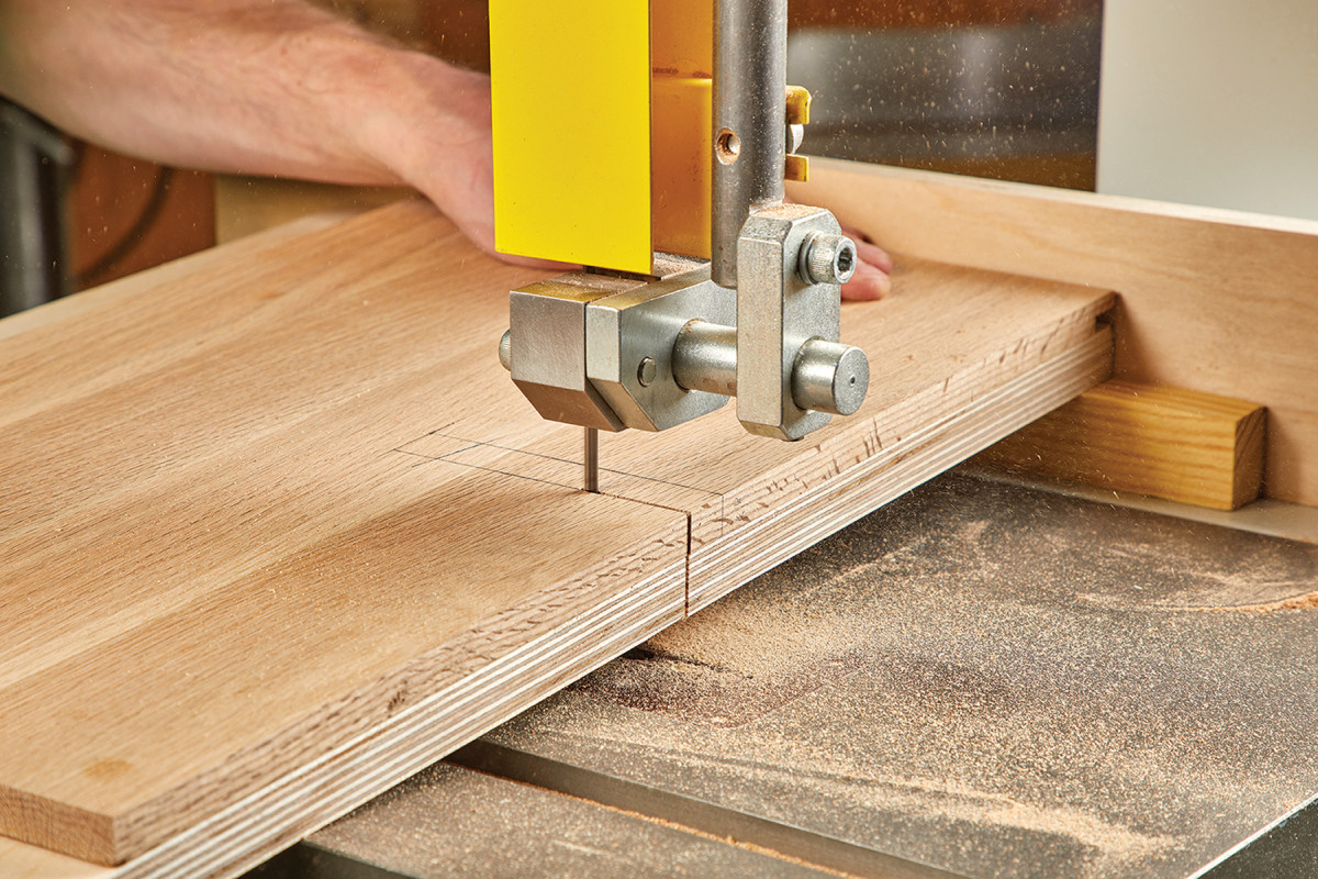
Layout the locations for edge half-lap joints on the side panels. Using the fence on the band saw, make stop cuts 1/2“ apart (thickness of the stretchers) and about 1/4“ shy of the joint depth of 1 1/4“. By doing this, you are allowing enough material to remain to chisel out the bottom of your joints at 6°. Since most band saws are only able to tilt in one direction, I built a simple jig to cut the angled walls for the bottom step (F) as shown. This jig is nothing more than a block of wood cut at a 6° angle and mounted below a piece of Baltic Birch plywood (dimensions for jig shown in project schematic at top).
9-13. This is where the fun really starts. You will be using a combination of a jig and/or tilting your bandsaw table to cut out the stool sides. Once you’ve drawn all of the layout lines on your sides, start by cutting the notch for the step, using the jig against your bandsaw’s fence to keep the 6° bevel on your cuts. You will be cutting into the plywood base of the jig. Thankfully all of the cuts are straight lines.
10.
11.
12.
13.
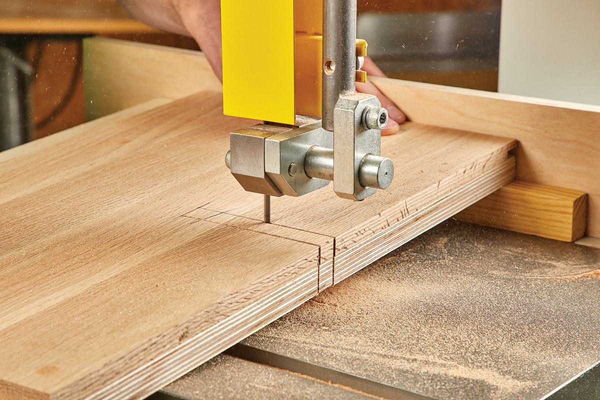
14-17. These complimentary cuts are done without the jig and the bandsaw table tilted to 6°. You’re basically mirroring the cuts you did with the jig so when the sides are assembled, you have flat planes for the step and stretchers.
15.
16.
17.
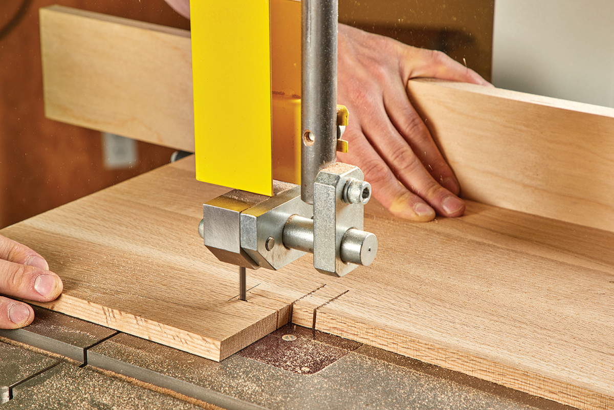
18-19. Flip the jig so it’s against the bandsaw fence to cut the notch on the mating side of the stool.
19.
Utilizing the fence, make your two stop cuts. Since the two side panels (A) are splayed as well as mirrored, you will have to rotate your jig 180° to make the two corresponding stop cuts on your right-side panel. Once your joinery is complete, you can go ahead and cut the 9° angled profiles of the two sides. If you are one to lack confidence in your ability to cut a straight line, cut close to your reference and finish with a block plane, edge sander, or sanding block. If you are still not satisfied, use one of your side panels as a template over at the router table with a pattern or flush trim bit.
20-21. Then tilt the table to 6° and make the remaining cuts. Confused yet? It’ll start to make much more sense as you set up and rehearse the sequence you need to make these cuts in. If you’re not confident in your bandsaw skills, you can practice with a piece of 1/2″ plywood or MDF.
21
Adaptive Parts
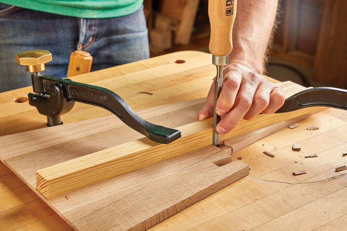
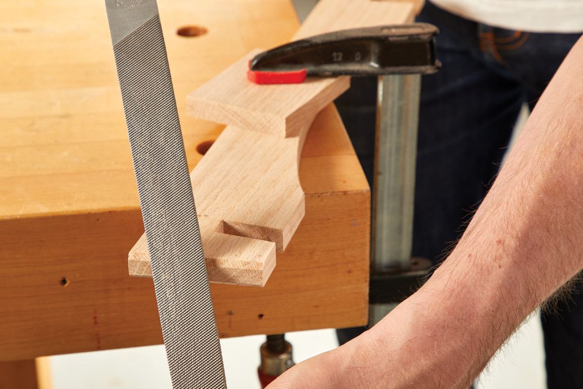
Utilizing the angled support block from the band saw jig, I went ahead and used this as a chisel guide to clean up the bottoms of the joints. This helped to ensure stability of the chisel and accuracy of the angle. Once the bottom of the two stretcher joints have been cleared out, flip the chisel guide to a 90° side and proceed to waste out the bottom of the mortise for the bottom step (E).
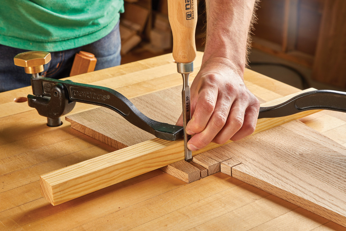
22-24. With all of your bandsaw cuts made, use a chisel to knock out the waste pieces for the step and stretcher notches. A scrap block with a 6° bevel on one edge helps me keep the chisel aligned.
23.
24.
Preparing the Stretchers
With the two sides of the stool complete, you can turn your attention towards the two stretchers. Start by ripping and cross cutting the two stretchers to their final dimensions. Layout the half-lap joints on one end of each stretcher. Using a stop-block in tandem with your miter gauge/table saw sled, raise your blade to the 11/4“ depth and make a pass. Flip your piece and proceed to make the same cut on the opposite side.
25-26. Next, lay out the notches for the stretchers. The stretchers are two different sizes, but the notches are the same distance from the ends of the stretchers.
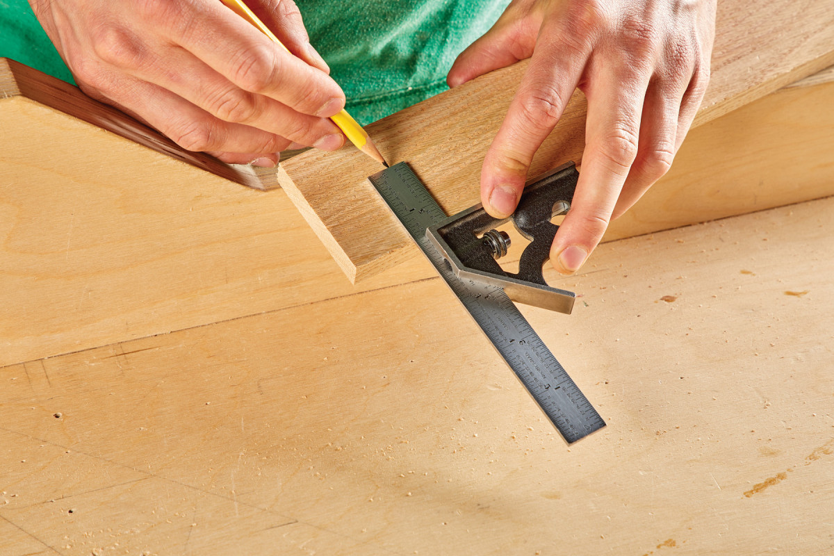
26.
This initial cut establishes the outside distance between the two half-lap joints. Now perform the same procedure for the inside cut and continue to make passes until all the material has been removed. Since there is an absence of glue at these connection points, it’s imperative that your edge half-lap joints have a firm fit to guarantee proper structural rigidity.
27-28. Tilt your table saw blade to 6° and cut the sides of each notch. Then, take multiple passes to clear the waste. Think through each cut before you make it.
28.
Layout the arc for the stretchers by marking the arc height on the centerline along with the distance between the two points. Transferring this line was done by using a 12“ stainless steel ruler compressed between the jaws of a Quick-Grip bar clamp (as shown).
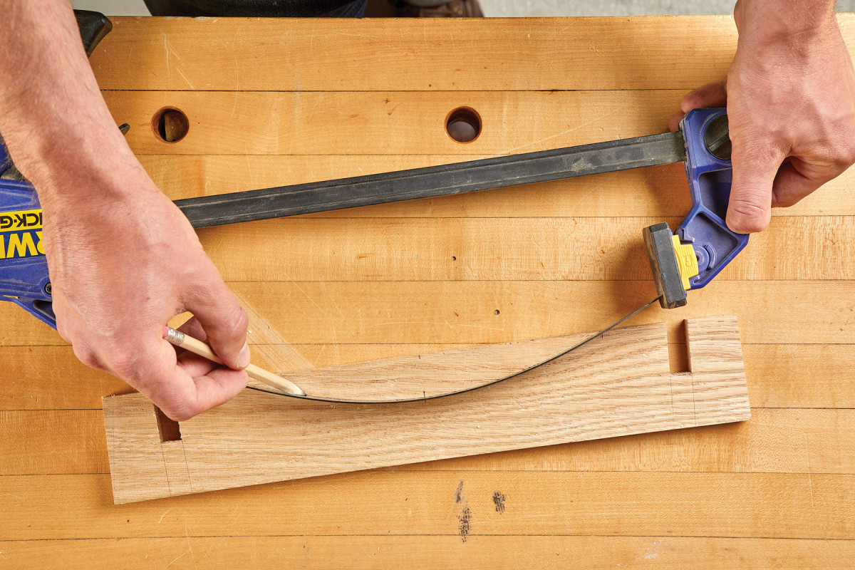
29. I use a clamp and flexible ruler to draw the curved cutouts on the stretchers.
Once this line is drawn, go ahead and mark the 6° miters on the ends of the stretchers. Both the arc as well as the miters were cut following the reference lines over at the band saw. Clean up any irregularities with a spindle/edge sander.
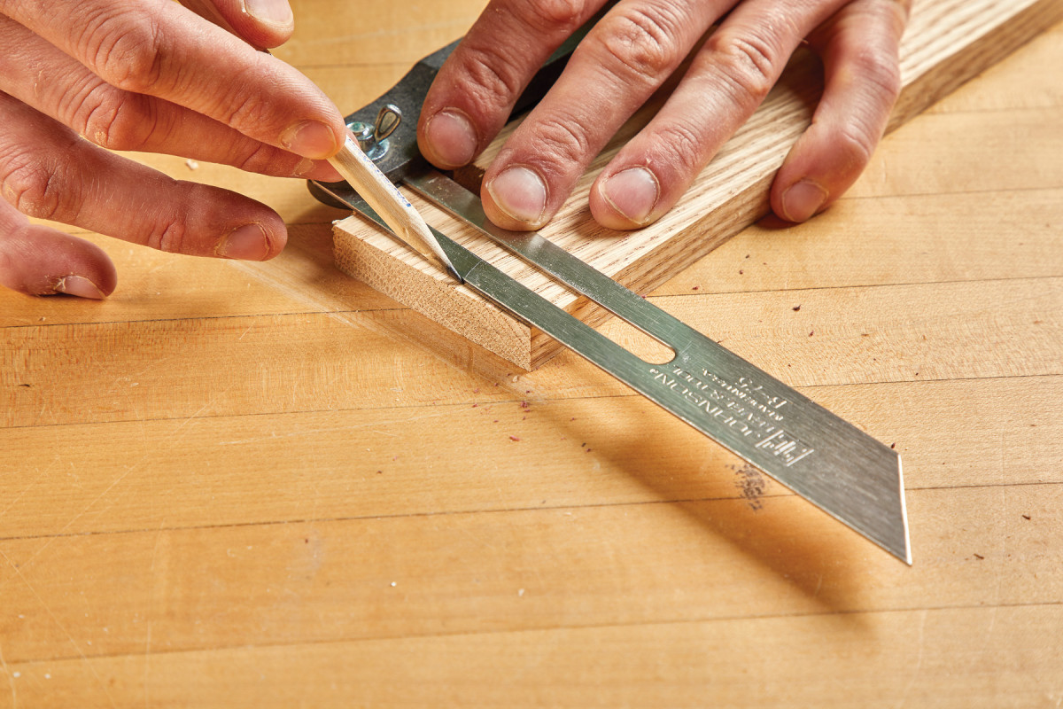
30. Use a bevel gauge to layout the 6° angled cuts on the ends of the stretchers.
31-32. Then head back to the bandsaw to cut the angled ends of the stretchers as well as the curved cutout.
32.
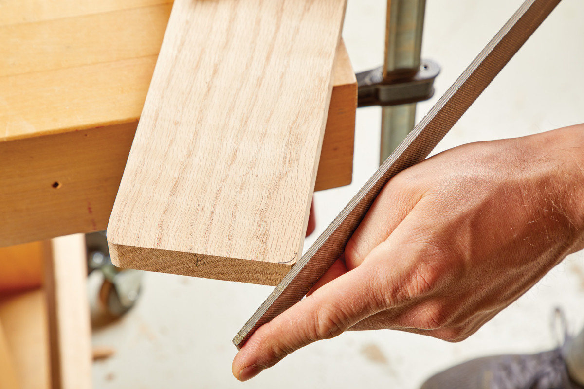
The last step is to give the mitered ends of the two stretchers an 1/8“ chamfer on either side of each face. This was done by clamping the stretchers down to a bench and using a bastard cut file at an approximate 45° angle.
33. Use a file to add chamfers to the ends of the stretchers. Aim for an 1/8″ chamfer, but it’s more important that they’re all visually equal versus exactly 1/8″.
Ascending Steps
The steps for the stool you will notice are 3/4“ opposed to the 1/2“ thickness of the two sides, bottom, as well as the two stretchers. This not only provides visual contrast to the piece but further reinforces the overall rigidity of the stool’s structure.
34. Add a small roundover to the bottom corners of the stretchers, again using a rasp.
Once both of these steps were ripped and crosscut to final length, I went ahead and applied a 1/4“ radius to each of the four corners using the same method as I did for the chamfers on the stretchers.
Assembly
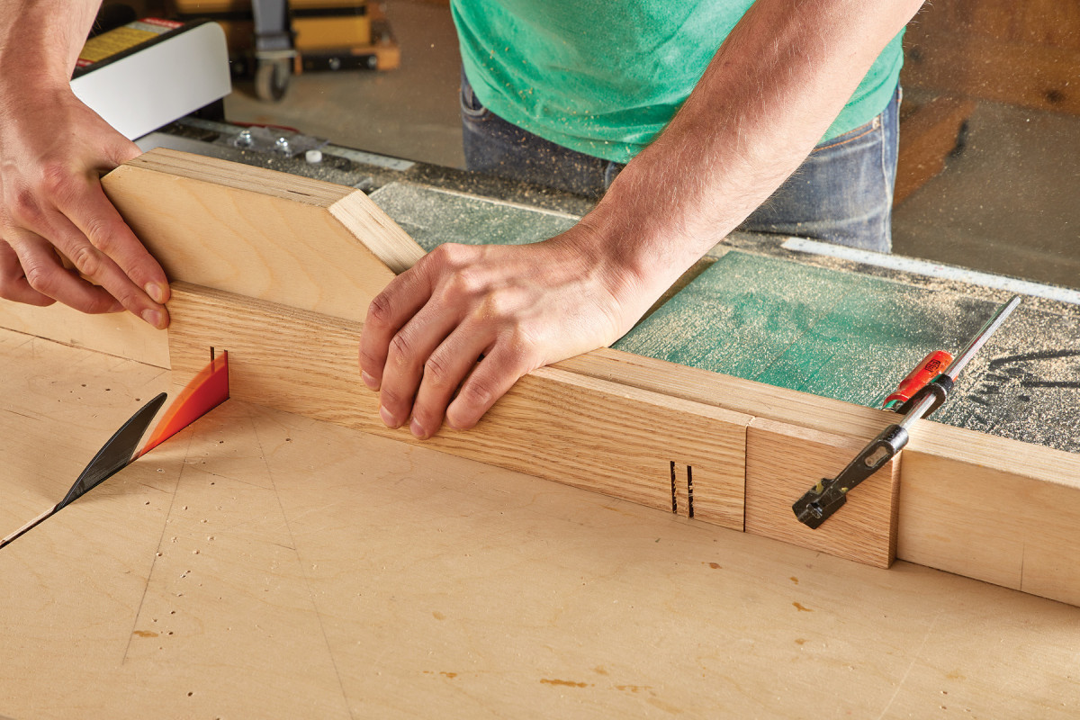
Even though this a project that lends itself to being fitted multiple times throughout the project, it never hurts to do a final dry fit before applying glue. Assuming you are an expert and all your pieces are cut to absolute precision, let’s attempt to be courageous. Place the bottom (B) between two sets of bar clamps. Start by applying glue to the rabbets on the side panels and bridge both sides together by applying the bottom stretcher (D) to its corresponding joint.
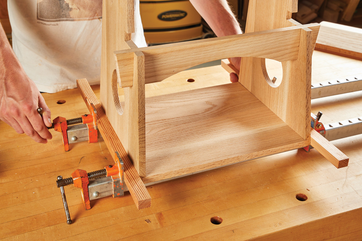
35. The only glue joint is along the bottom rabbets, so start there. I used a couple of cauls beveled at 6°. Add the lower stretcher to help keep things aligned.
Now lower the entire assembly down so that the rabbets fit snuggly on either side of the bottom panel. I snuck a couple of caul blocks cut to 6° on one side between the clamp jaws and the work piece. This provided the piece with equal and adequate clamping pressure across the length of the joint. Once the bottom is clamped in place, begin to add the top stretcher. After the glue has dried it’s time to apply the top and bottom treads.

36-37. Next add the top stretcher. It’s just held in place with friction (so it might need a few mallet taps to seat it).
 For this application I chose to use 11/4“ headless brad cut nails from the Tremont Nail Company. These nails work great as they are low profile, resist twisting, and (by design) possess a lot more holding power than a traditional wire nail. There is no exact formula when placing the nails, just so long as they are spaced adequately enough to apply a uniform amount of pressure. Since these nails come in bulk, I went ahead and added a few extra nails across the rabbet joints for an extra line of security.
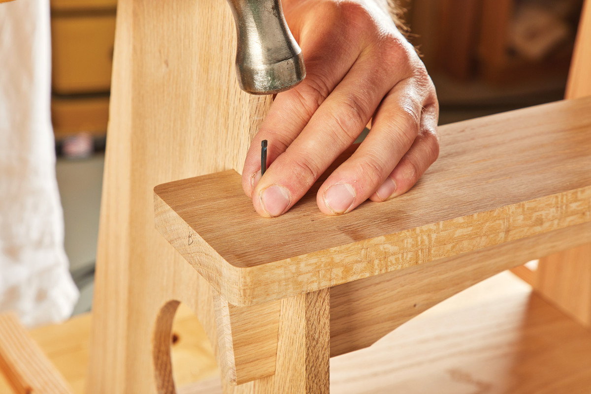
38. Finally, attach the top and bottom treads with nails. Because I like the utilitarian look, I also nailed the rabbets for reinforcement.
Finishing Time Machine
Instead of settling on a stain/finish combination that seemed “safe” in its universal appeal, I wanted something that would be more suitable for a piece of this time. One that did not bastardize the historic qualities/character of the piece with a modern finish. While I would have preferred to use the original Japanese lacquerware finishing technique know as negoro style, due to its laborious process and inherently poisonous nature, proposing it without proper experience just seemed negligent.
Instead, I found mixing red, water based aniline dye with weather accelerator yielded an acceptable appearance that closely emulated the aesthetic of this historic style. Applied with a foam brush and left to dry overnight, finish the piece off with a couple coats of lacquer to protect as well as illuminate the dye below.
Here are some supplies and tools we find essential in our everyday work around the shop. We may receive a commission from sales referred by our links; however, we have carefully selected these products for their usefulness and quality.