


We may receive a commission when you use our affiliate links. However, this does not impact our recommendations.
Using a Dial Indicator and Calipers to Achieve Tight Fitting Finger Joints
Greene & Greene (G&G) finger joints are distinctive in their size and spacing. The joints are unlike any other finger joint I’ve seen, which is probably why I’ve been so adamant about learning how to produce them. One of the methods I found for cutting G&G finger joints involved making templates for various finger sizes and a handheld router. You could easily amass a large collection of templates since the G&G motif is synonymous for having several finger spacing configurations within a single furniture piece. Darrell Peart’s method of machining finger joints on the table saw, with calipers and a dial indicator on a dado sled, made the most sense to me. This method required no templates and the fit could be dialed in with laser-like precision without much fuss.
Construction
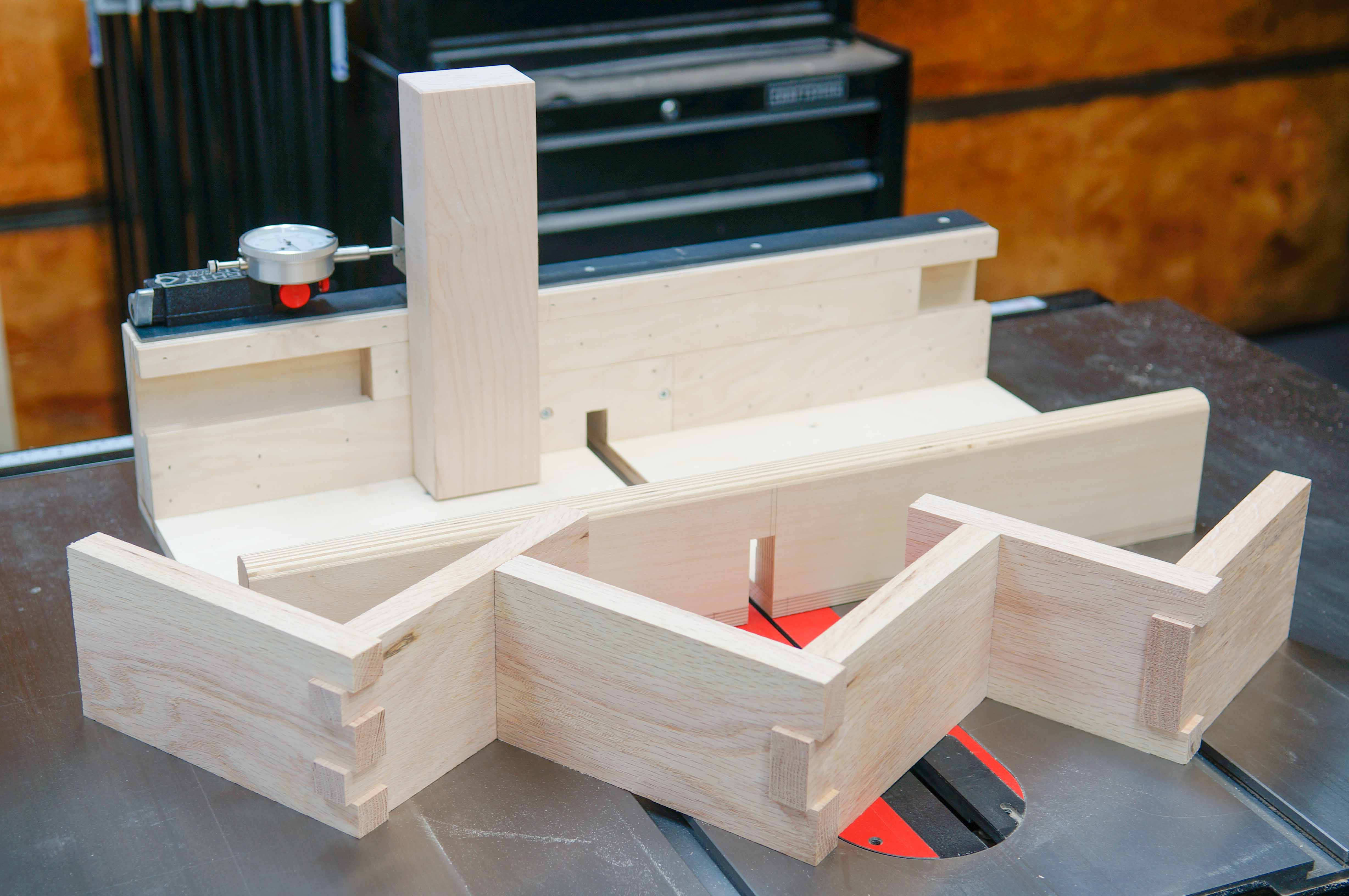
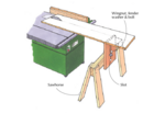
The dado sled is not much different than your normal cross-cut sled. The base of the sled has runners that engage the miter slot on your table saw. The front fence helps to stabilize the base while the back fence is perpendicular to the table saw blade and supports the workpiece. The features that are unique to this dado sled are a moveable track attached to a large hardwood stop block, a replaceable zero clearance insert, and a flat metal bar at the top of the fence. The moveable track and large hardwood stop block allow for fine adjustments while offering support and keeping the workpiece perpendicular to the sled. The zero clearance insert minimizes tear out and can be replaced as it gets chewed up by the dado blade. The flat metal bar is a mounting surface for a dial indicator attached to a magnetic base which allows you to move the stop block within 1/1000”.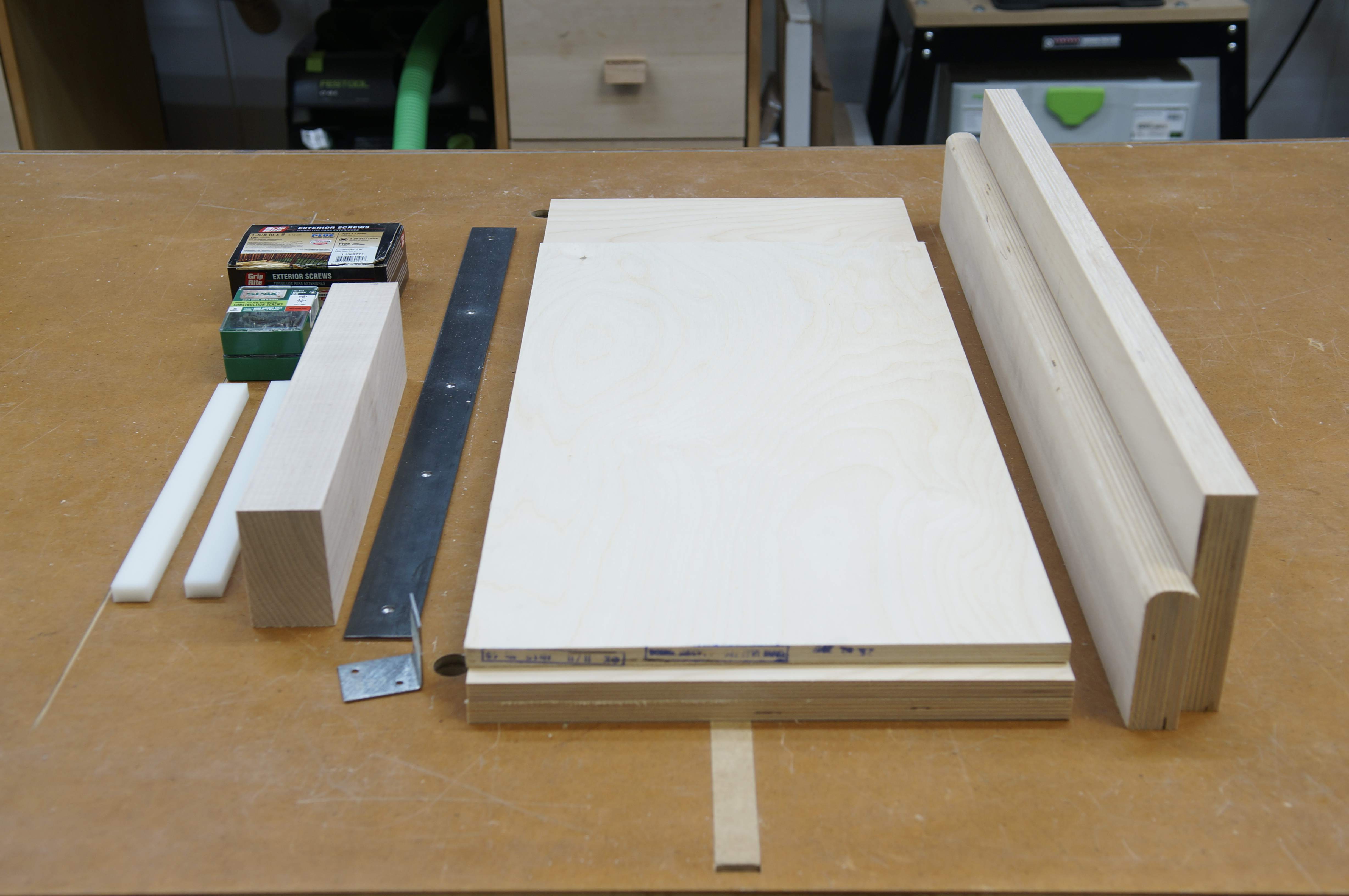 The dado sled consists of 1” and 1/2” Baltic Birch plywood, a square and flat block of hardwood (in my case Hard Maple), 1-1/2” steel flat bar, a corner bracket, UHMW runners, and 3/4” and 1-5/8” screws.
First, I attached the miter slot runners to the base of the sled. I used a couple of cans of mineral spirits and the table saw rip fence to keep the base aligned and in place while I drill pilot holes and countersunk 3/4” screws. For the miter slot runners, I used a couple of strips of UHMW (Ultra High Molecular Weight) plastic. Next, I attached the front fence (1” Baltic Birch) to the base of the sled. The front fence adds rigidity to the base, so making sure the front fence is square to the base is not critical. However, it is important to note the maximum width of your dado set and the blades’ line of travel. You don’t want to accidentally run your dado set over a nail or screw.
 I use the table saw rip fence and a couple of mineral spirits cans to keep the base of the sled in place as I attach the runners.
 Consider the maximum thickness of your dado set when attaching the front fence and back fence making sure screws are not in line with the blade.
The back fence consists of a single layer of 1” Baltic Birch and two layers of 1/2” Baltic Birch. The layers are attached using 3/4” brad nails and glue. The moveable track is not attached but rather used as a spacer. To ensure the pieces remain flush along the bottom of the back fence, I push the pieces up against a shop made right angle clamping guide as I glue and nail down the pieces. Once all the layers are attached, the two pieces of the moveable track are attached to each other so that the two pieces move as one. Then, the zero clearance insert is attached using two 3/4” screws. Screws are used to make the zero clearance insert easily replaceable. Lastly, the flat metal bar is attached to the top of the fence using screws. This will become the point of attachment for the dial indicator attached to a magnetic base (Mighty Mag.)
 The back fence consists of one layer of 1” Baltic Birch and two layers of 1/2” Baltic Birch attached with glue and 3/4” brad nails. I use a shop made right angle clamping guide to keep the bottom of the fence pieces flush as I glue and nail down the pieces. Make sure nails are not in line with the blade. The moveable track is encapsulated between the layers of Baltic Birch.

The zero clearance insert is attached to the back fence with a couple of screws.
The track should glide smoothly with a light application of furniture paste wax.

Attaching the flat metal bar with some screws.
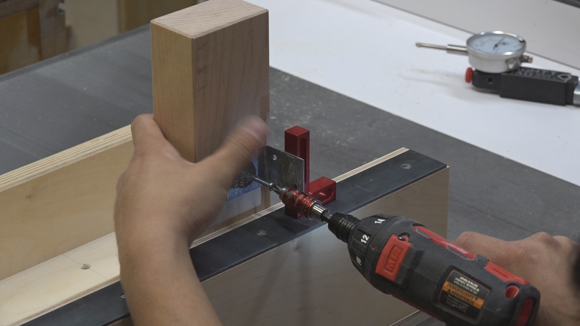
I make a partial kerf cut into the sled and use a precision triangle to square the back fence to the saw kerf within the sled. Once the fence is square I attach the fence with some 1-5/8” screws. I want to make sure the stop block is perpendicular to the fence and base of the sled. To do so, I attach a clamping square to the side of the hardwood stop block (Hard Maple). CA glue helps tack down the stop block to the moveable track. I then remove the track with the stop block and run several 1-5/8” screws through the back of the moveable track. Finally, I attach the corner bracket to the back of the stop block.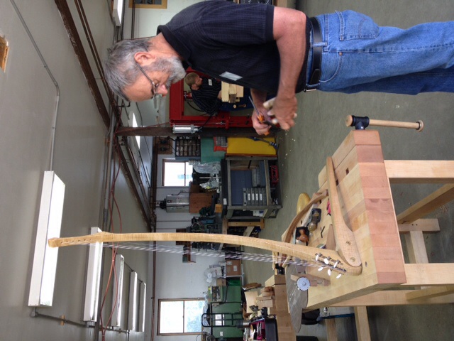
Using a triangle to ensure the back fence is perpendicular to the kerf of the saw blade.

Using CA glue to tack down the stop block and a clamping square to keep the stop block perpendicular to the base of the sled. I used a 1/32” spacer placed underneath the stop block to ensure the stop block doesn’t bind on the base of the sled.

Securing the stop block with screws.
Attaching the corner bracket to back of the stop block.
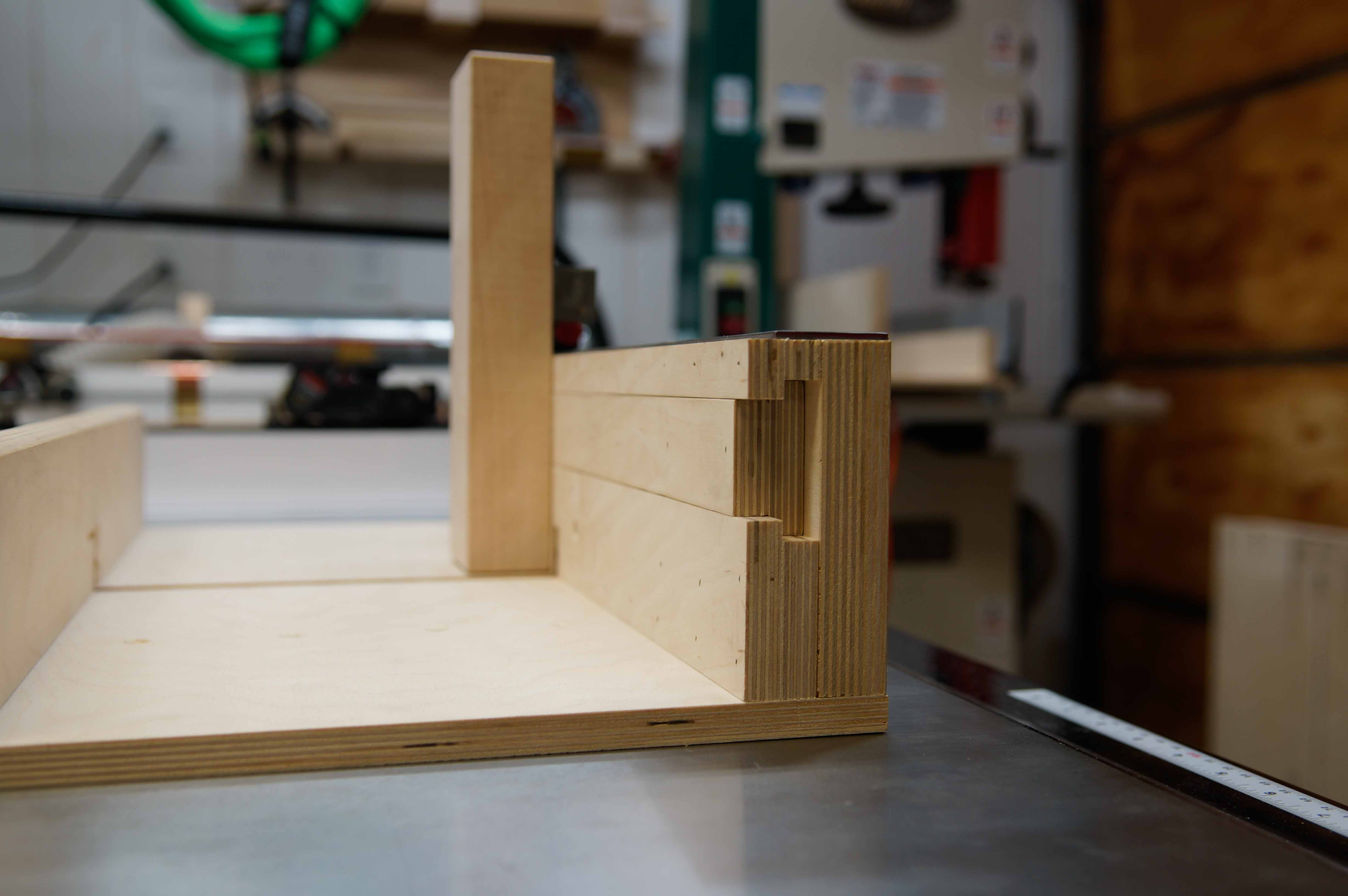
The moveable track encapsulated within the fence of the sled.
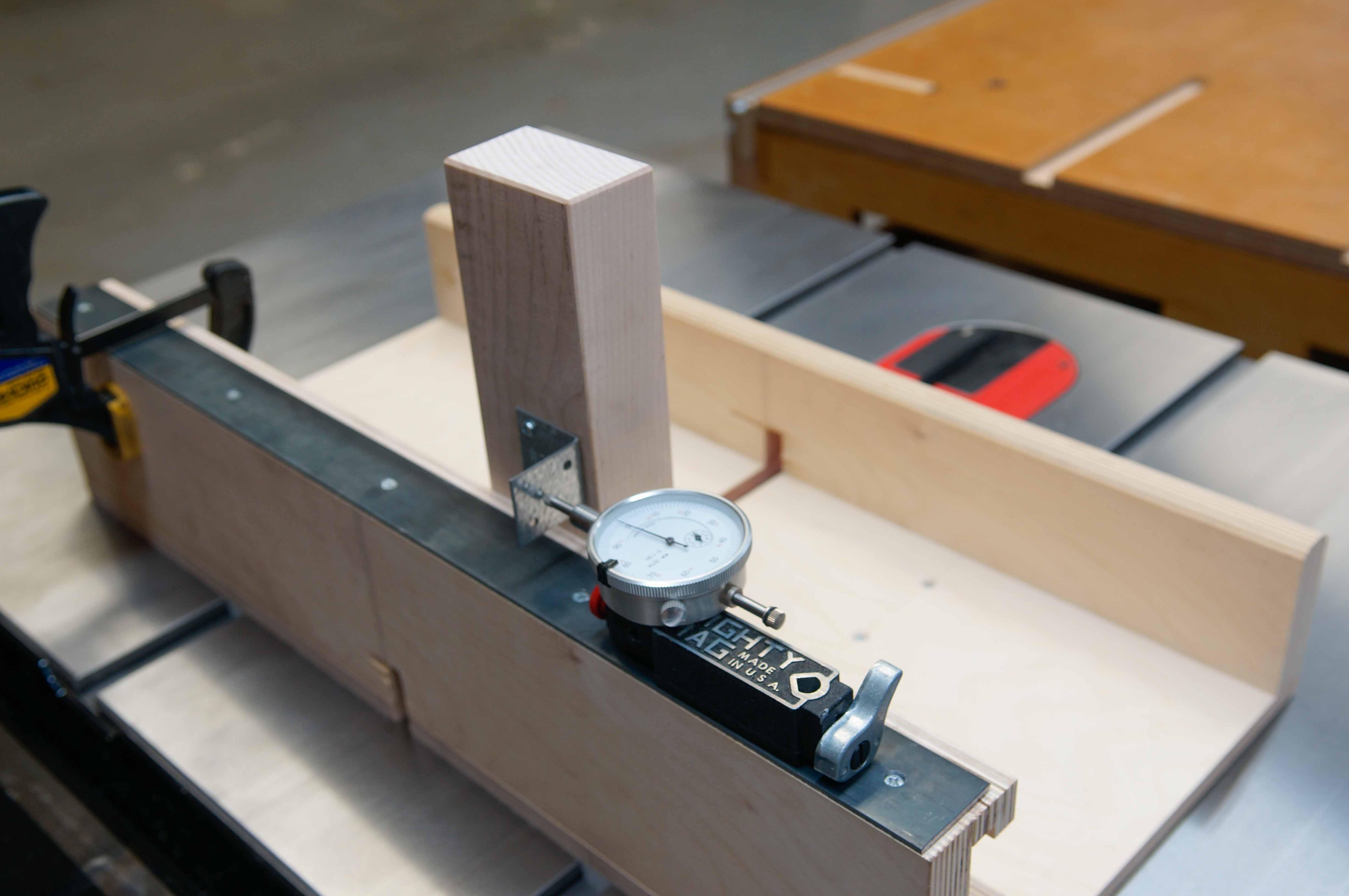
The dial indicator attached to a magnetic base contacting the corner bracket on the back of the stop block.
In Practice:
3-Finger Joint
To make the finger joints on this dado sled one side of the work piece is machined, rotated horizontally, then the other side of the work piece is machined. This means that I’m referencing off of the center line of the workpiece. In order for this method to work all your pieces need to be exactly the same width. You’ll also need a pair of test pieces to dial in the fit.
First, I choose the width of my dado set to be smaller than the width of my fingers, but wide enough to define the width of the finger by flipping the workpiece horizontal and taking a second pass. For me, that’s usually 5/8″ or 3/4”. Next, I set the height of the dado set to about 1/4” greater than the thickness of my material. This gives the signature protruding finger joint look. I then set the stop block to define the center finger. I make my first cut, flip the board horizontally, and then make my second cut. If I like the size of the center finger I’ll do this for all of my drawer fronts making sure to hog out the waste on either side of the center finger. Typically, the drawer front receives the center finger.
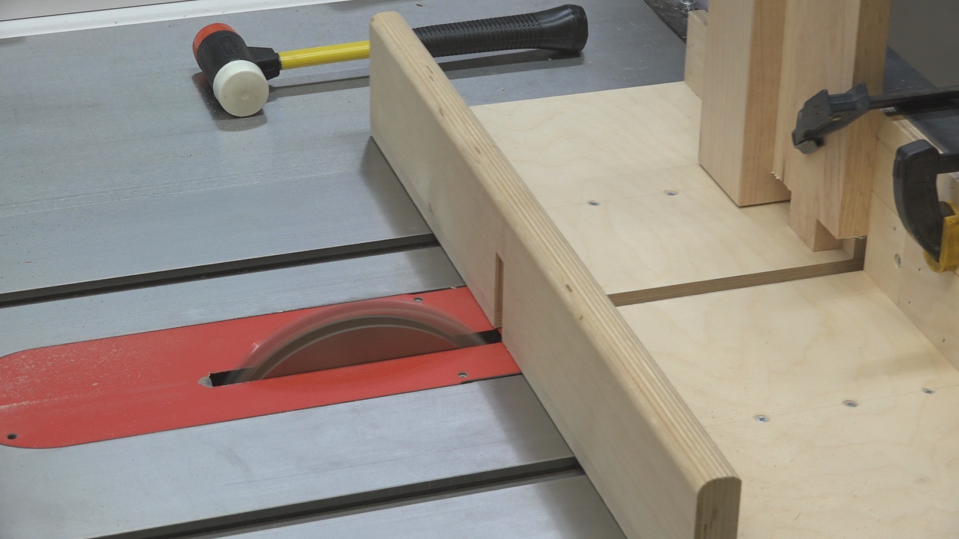 After defining the size of the center finger I hog out the waste on either side of the center finger.
Now I’ll define my outside fingers, but I’ll purposefully oversize them. Again, I’ll make a cut, flip the board horizontally, and make another cut. Now I’ll take a measurement with my calipers. The center finger measures 1.519”, while the space between the two outside fingers measures 1.493”. That’s a difference of 0.026”. Divided by 2 and I have 0.013” that needs to be removed on each side of the inside walls of the outside fingers. I’ll add 0.001” of clearance for a total of 0.014” that needs to be removed on each side. I’ll position the dial indicator against the corner bracket on the stop block, loosen the clamp holding the track attached to the stop block, and with light taps of a mallet I’ll move the stop block over by 0.014”. I’ll take a pass on each side of the outside fingers. What I’m left with is a tight fitting finger joint.
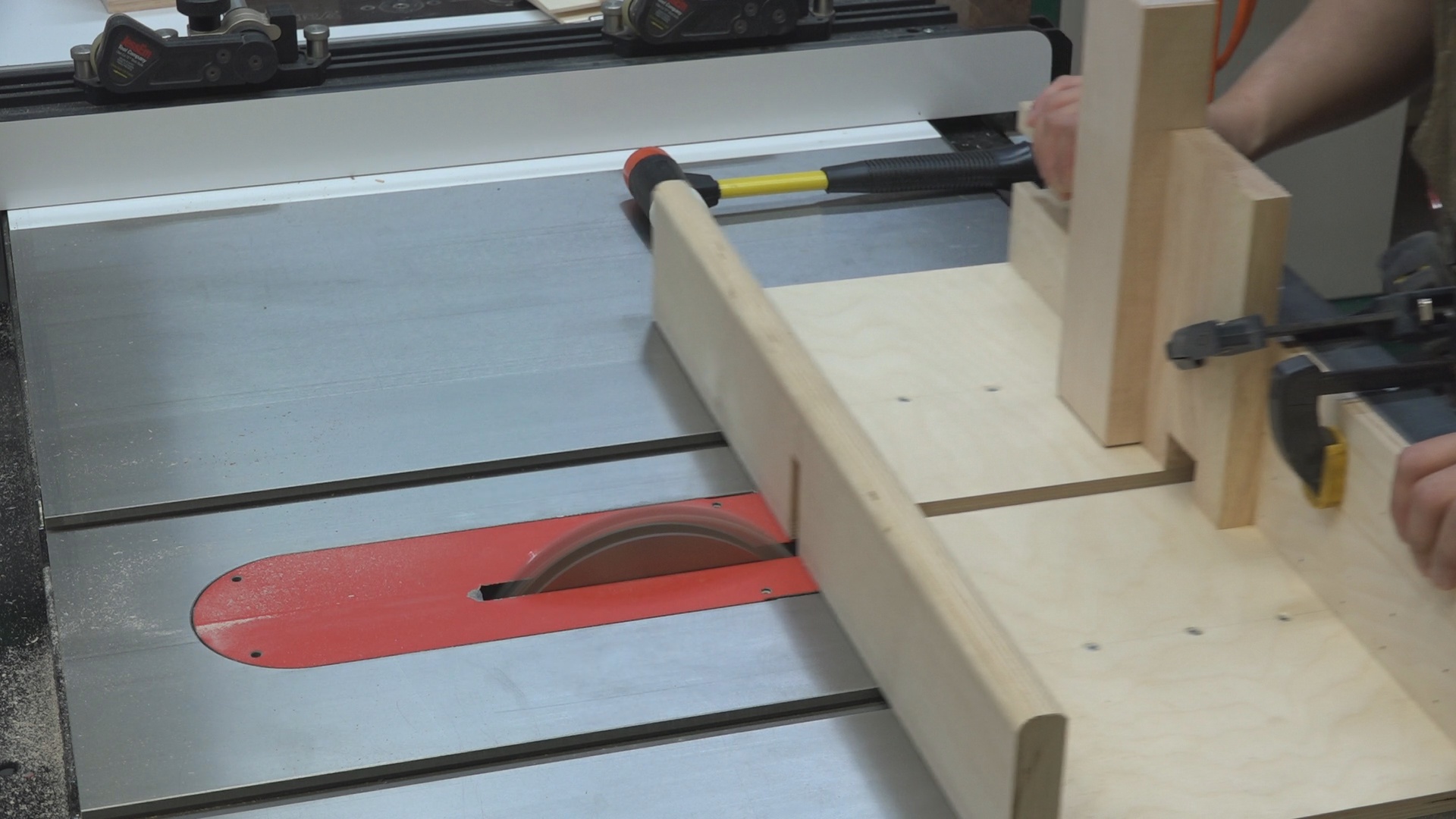 I purposefully oversize the outside joints to dial in the fit.
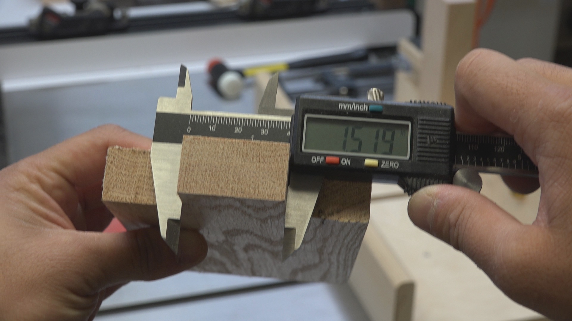 Width of the center finger.
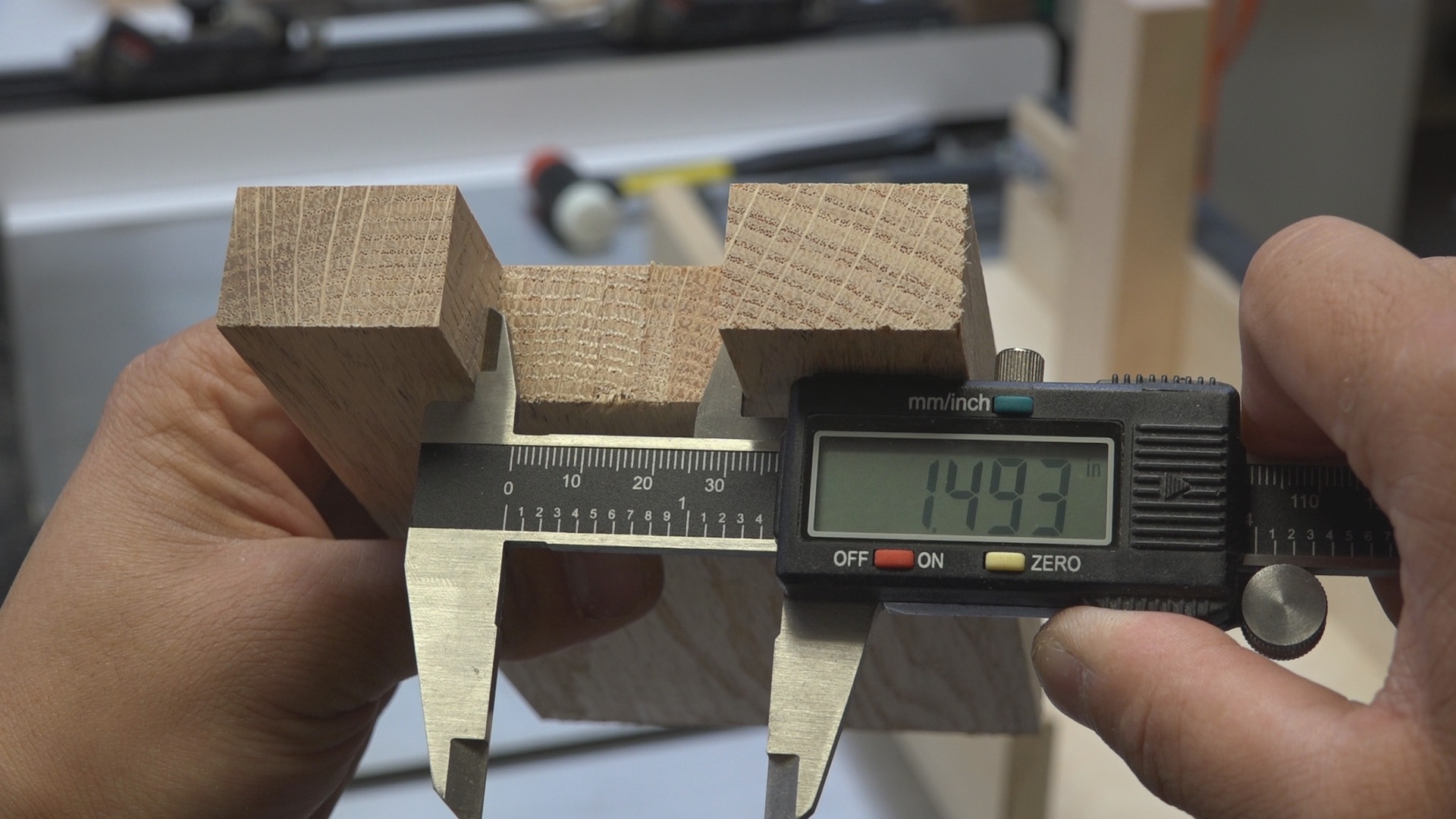
Width of the spacing between the two outside fingers.
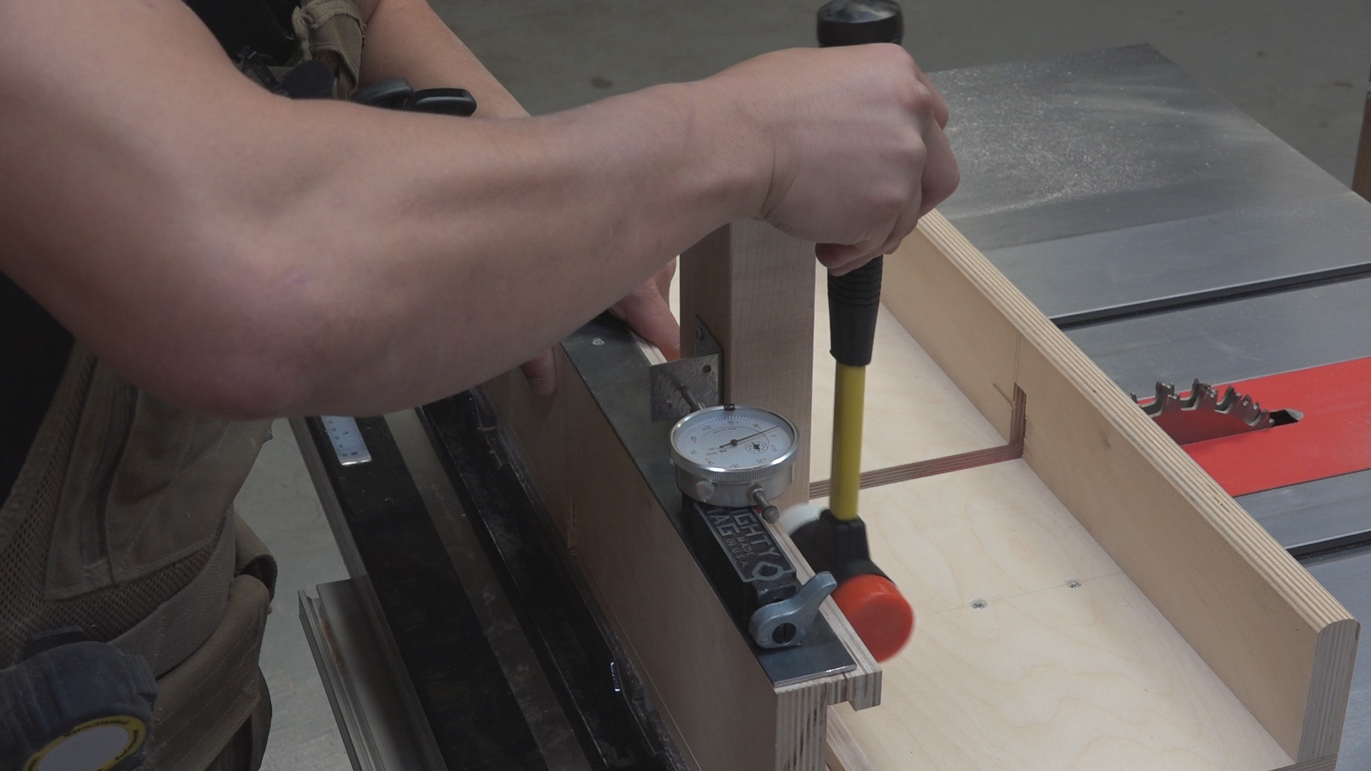
Light taps with a mallet until the dial indicator reads 0.014”
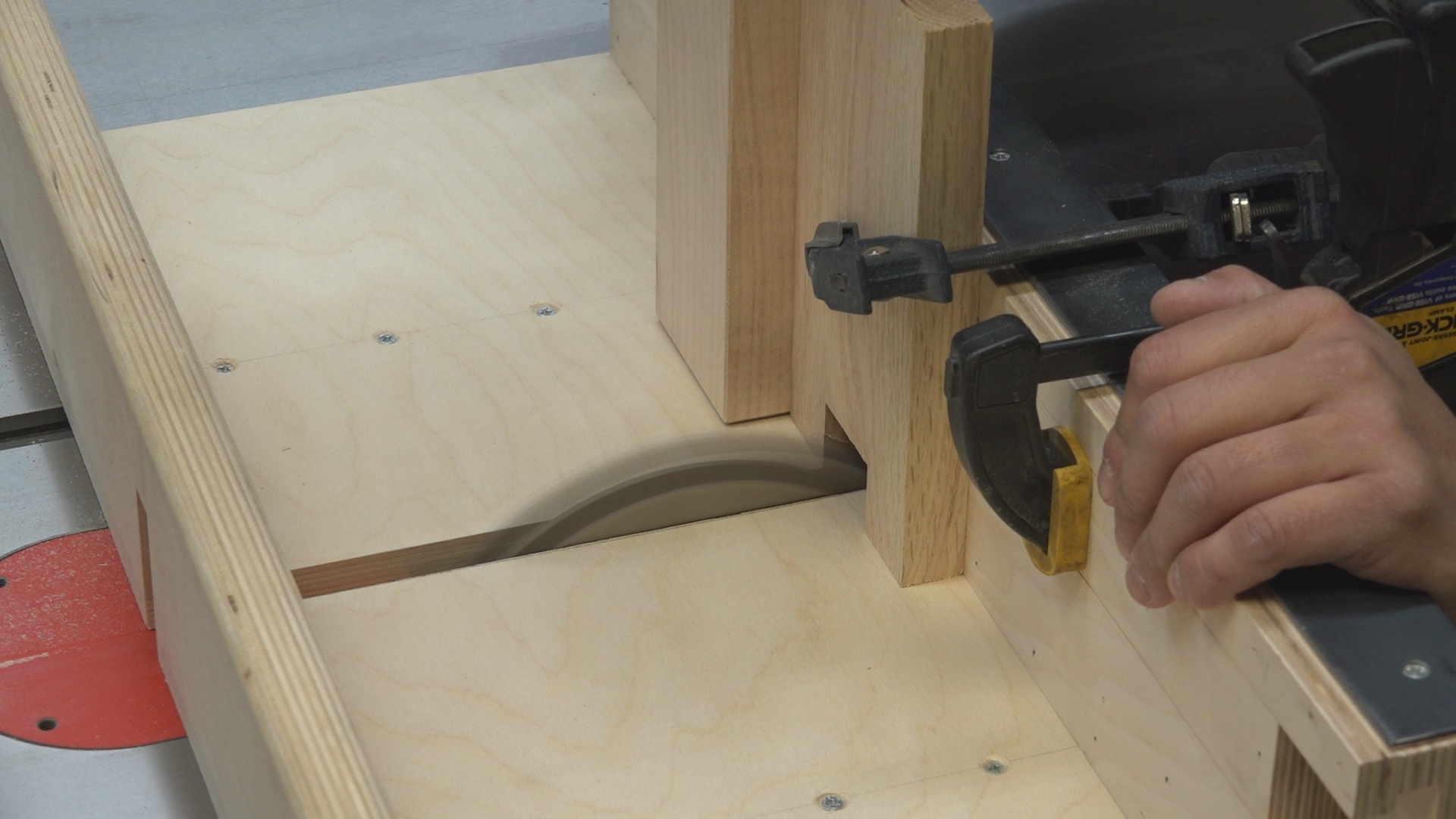
Taking a final pass on each side of the outside finger joints. 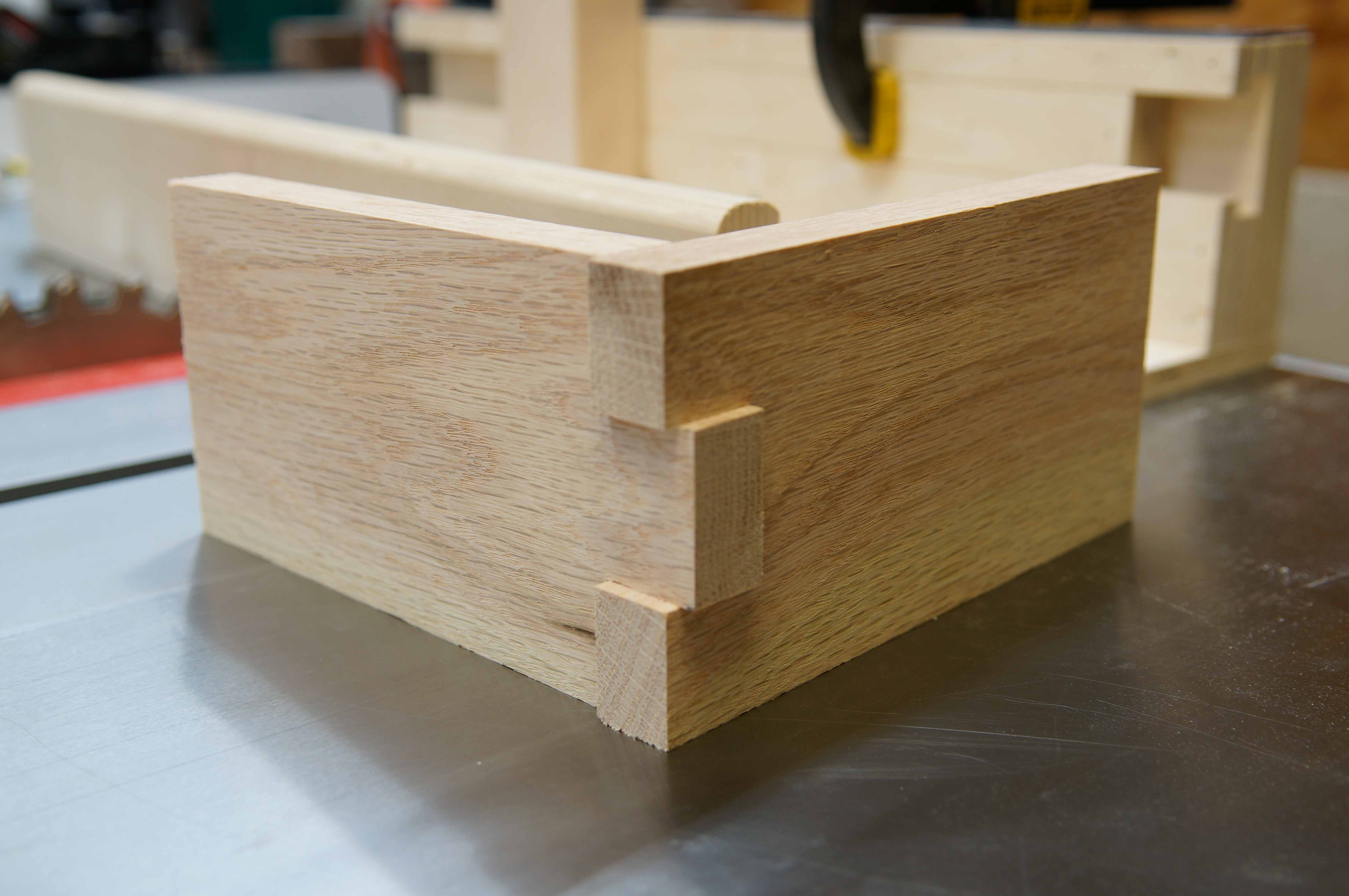
A tight fitting 3-finger joint.
5-Finger Joint
A 5-finger joint is a little trickier. The center finger is initially defined on the test piece. Once a fit is refined, all the subsequent drawer pieces are cut without hogging out the waste to either side of the center joint. This is because the outside joints need to be refined. I’ll take my test pieces over to the miter saw and chop off the fitted center joint. Now, I’ll define the two outside joints. Once they are properly fitted I’ll cut all of the subsequent pieces. The image below shows the progression of a 5-finger joint.
The center joint of a 5-finger joint needs to be refined on the test piece first. Then, all subsequent drawer pieces can be cut making sure to leave the waste on either side of the center joint to give room to define the outside joints. 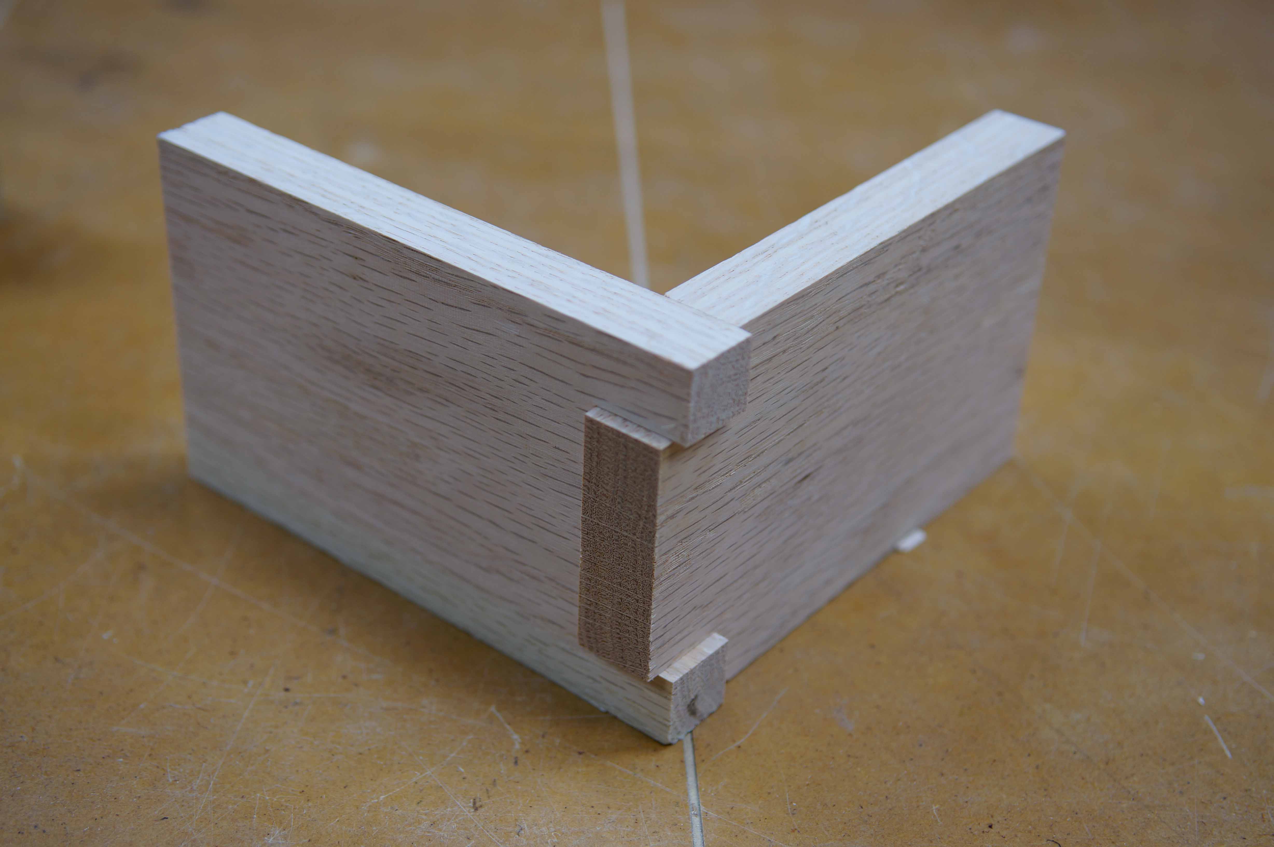 I cut off the test fingers for the center joint and reuse the test boards to define the outside joints. Once I refine the fit for the outside joints I can process all subsequent drawer pieces.
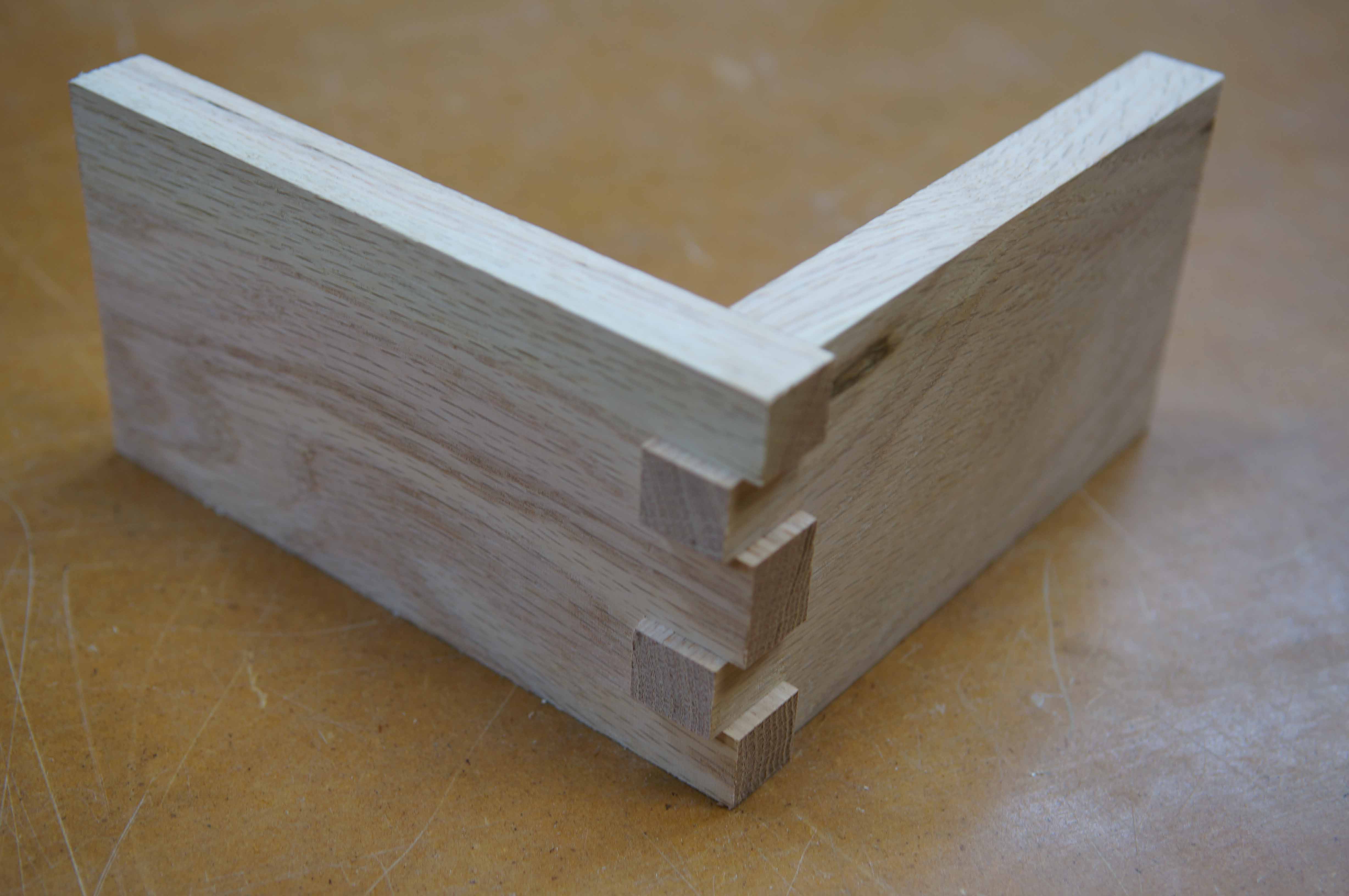
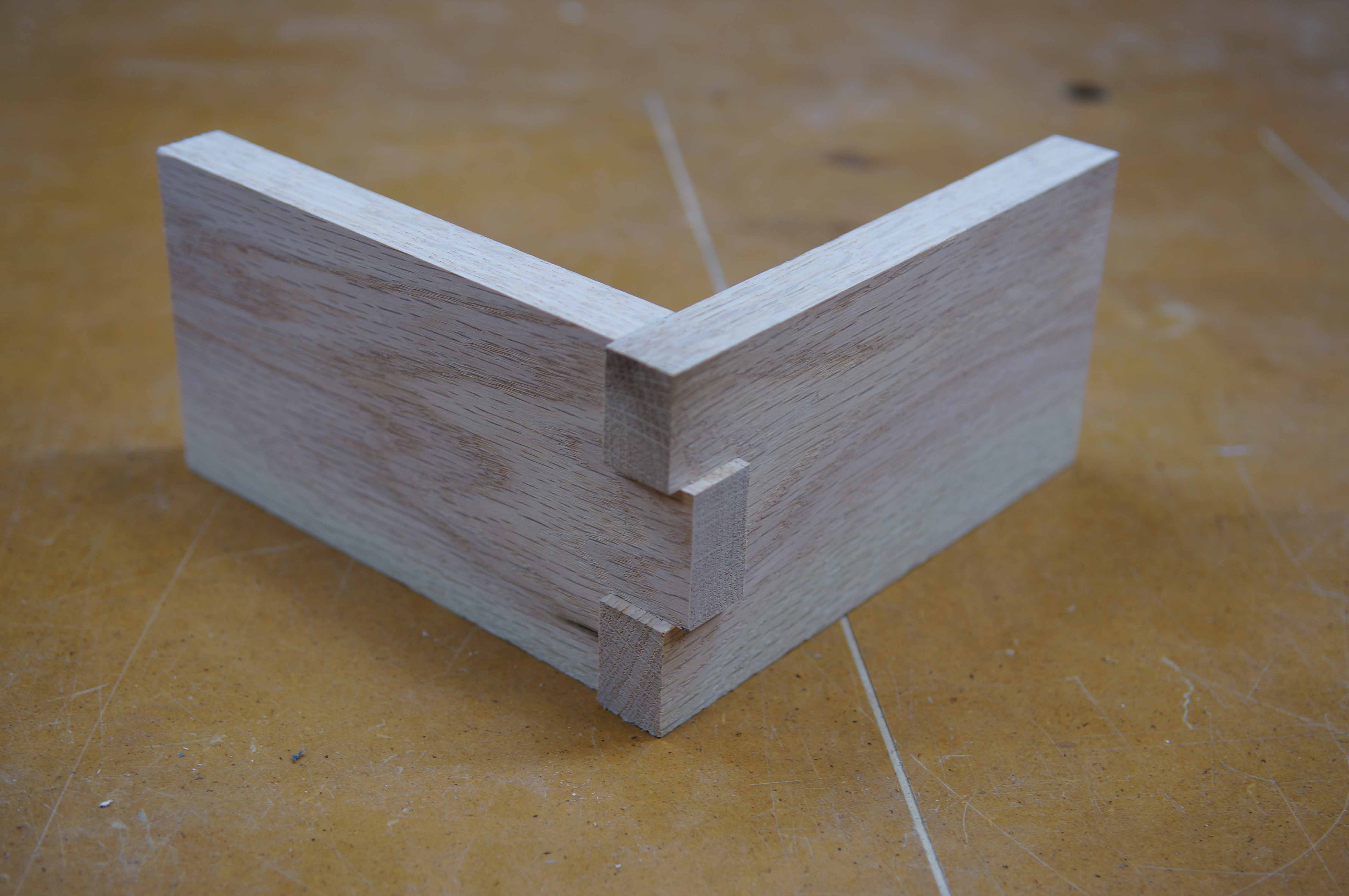
The final 5-finger joint.
– Huy

Huy is a full time aerospace engineer and hobby woodworker, documenting and learning the craft out of his garage workshop in Huntsville, AL.
Here are some supplies and tools we find essential in our everyday work around the shop. We may receive a commission from sales referred by our links; however, we have carefully selected these products for their usefulness and quality.


Excellent jig!