We may receive a commission when you use our affiliate links. However, this does not impact our recommendations.
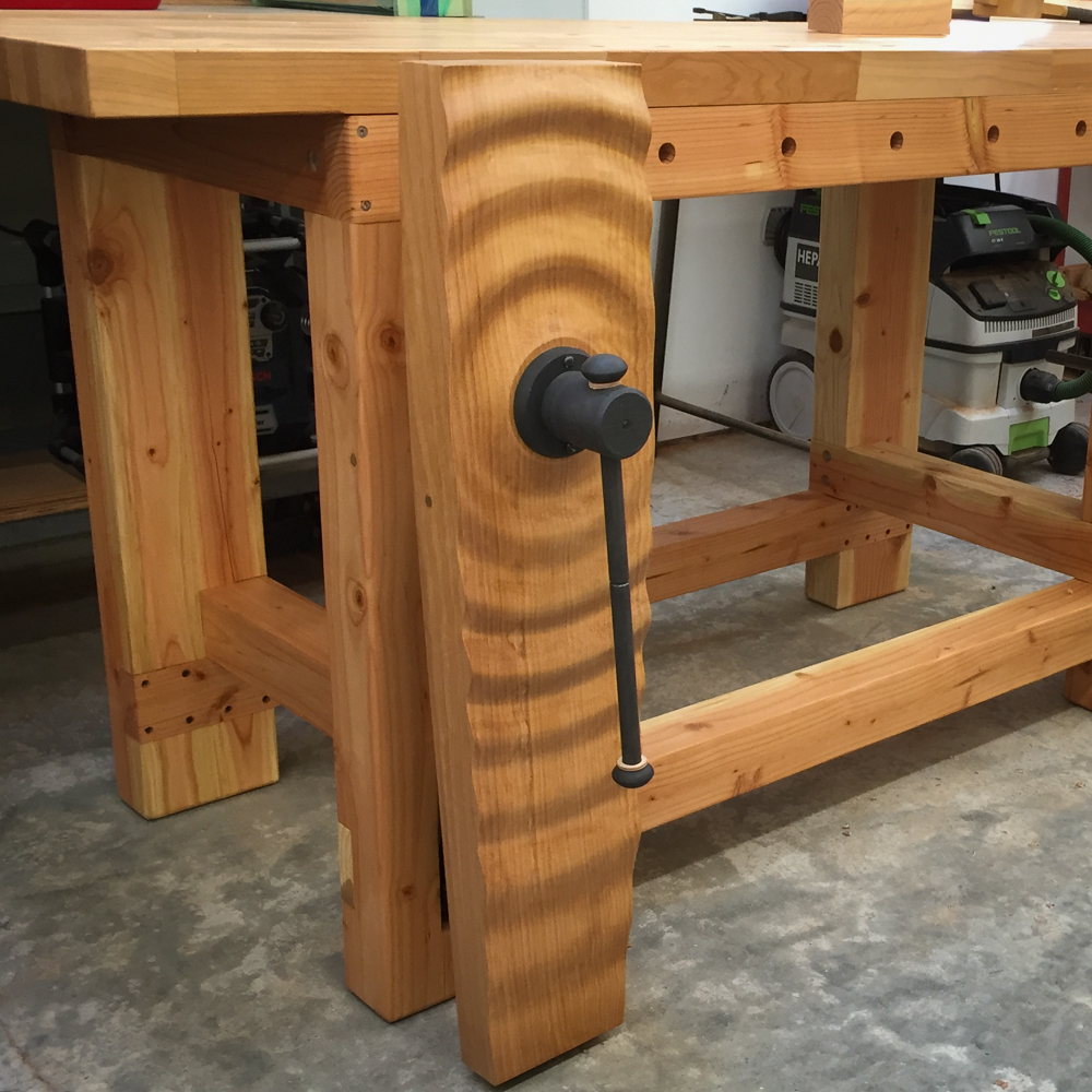
How to make a ripple texture on a workbench leg vise.
In earlier posts, I used CAD software to create the 2D design for the BARN Workbench vise chop and the I built a pin registration board for two-sided machining on my CNC. Rather than a square and blocky shape for the vise, I used 3D drawing tools in Rhino3D to give it a gently curved shape. Now, for the fun part: creating 3D textures and patterns that are applied to the front face of the vise.
Let’s start with the 3D ripple shape of the vise on the prototype workbench. It’s easier to show you in a series of screen captures. Here’s how it was made…
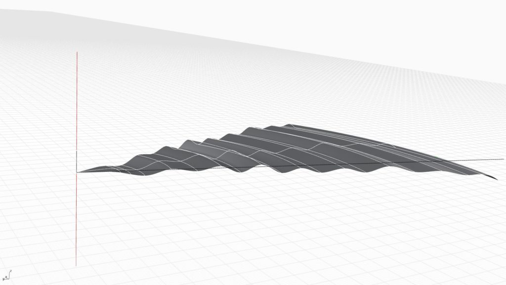
If you took a verticle slice of a ripple, you’d end up with a squiggly line. This is what’s called wave amplitude. It’s the frequency of the wave and it’s just a single line. Starting from the vertical line I added for alignment on the left, I used my curve tool to draw a squiggle toward the right.

Next, I used a Rhino3D tool called “revolve”. Revolve is just like “extrusion” that I mentioned earlier except you rotate around a point. Most 3D CAD programs will have similar tools. In this case, I’m starting to revolve around the vertical red line on the left.
And, continue all the way around…
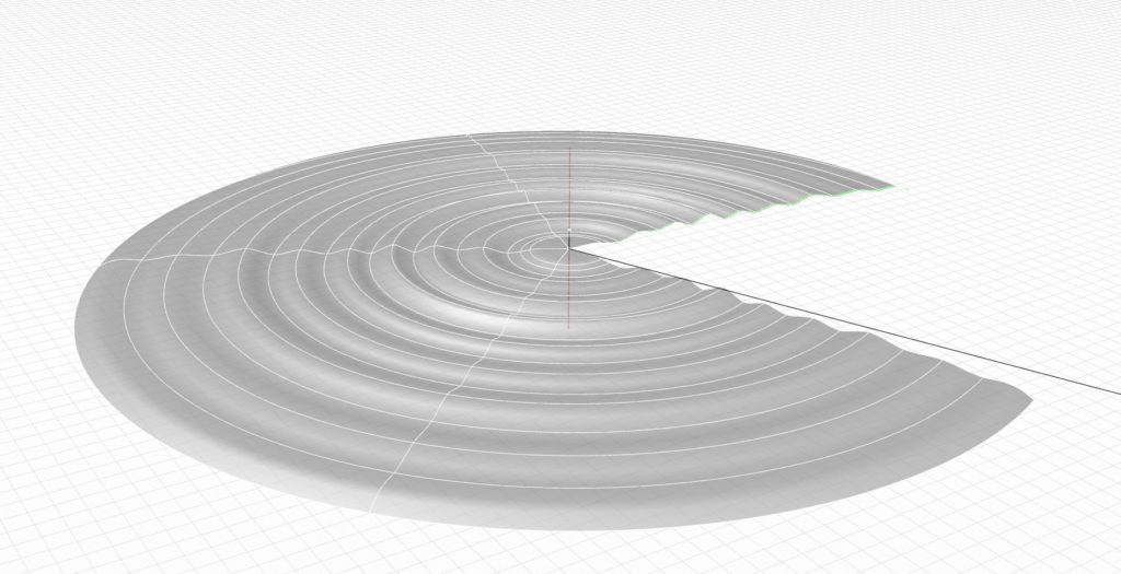
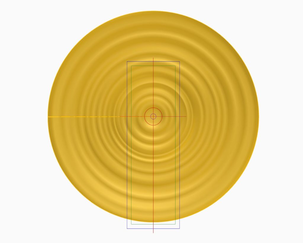
A completed 360-degree revolution.
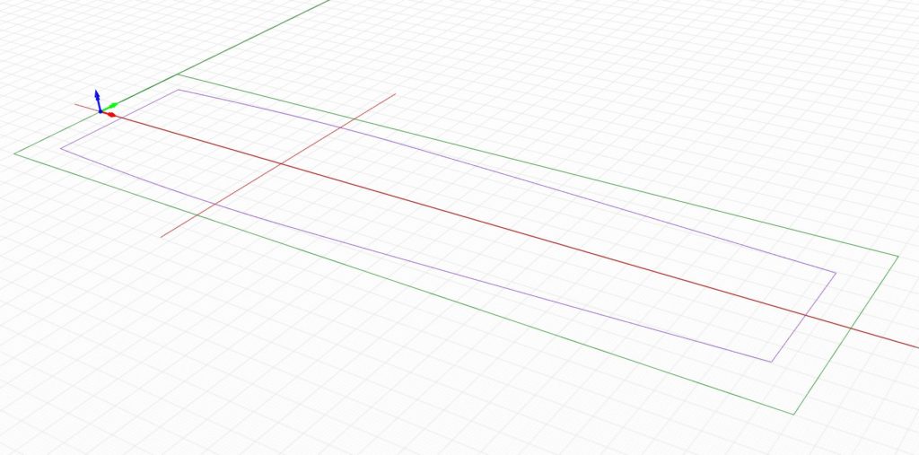
The next step is to align my large ripple surface with the vise stock lines I drew in the first post of this series. See, I told you those red alignment lines I drew would come in handy.
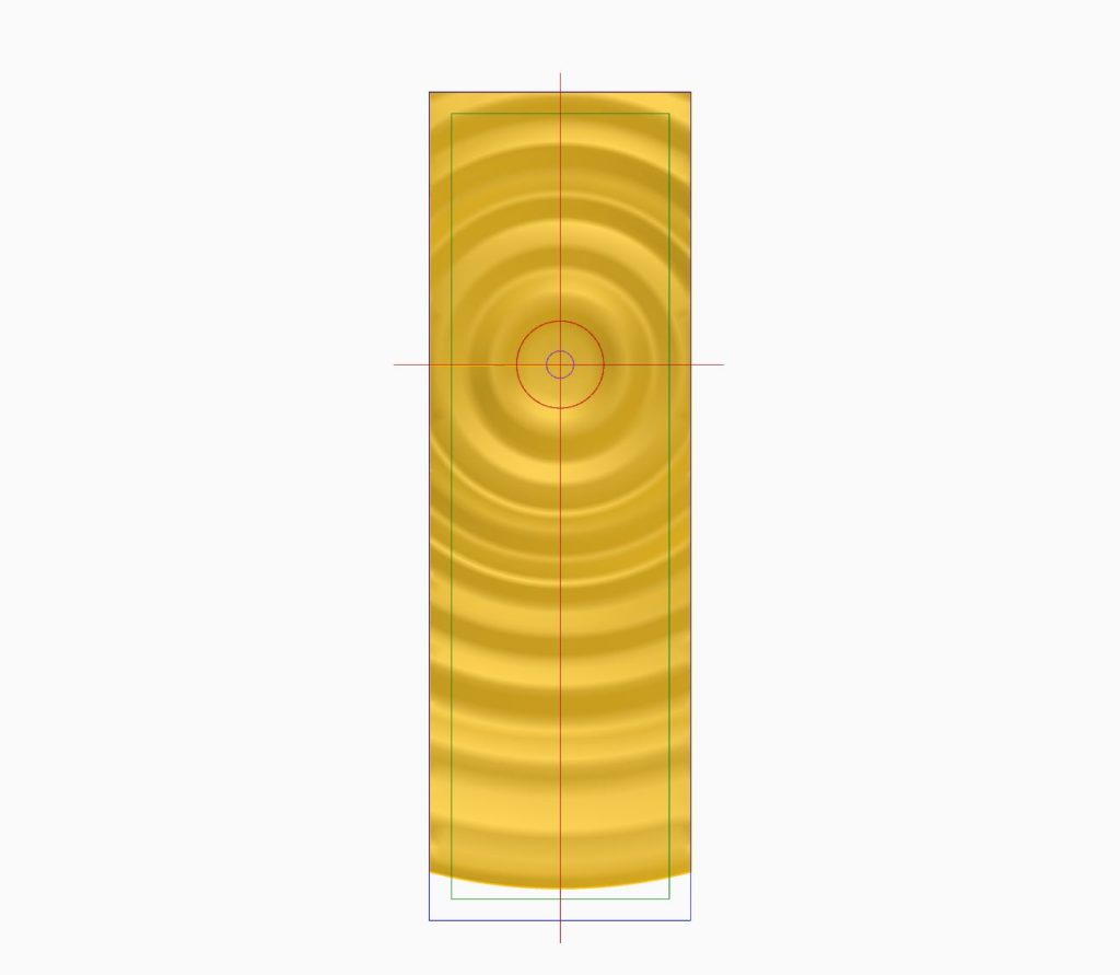
Next, I trim off all the parts of the wave surface that I don’t need.
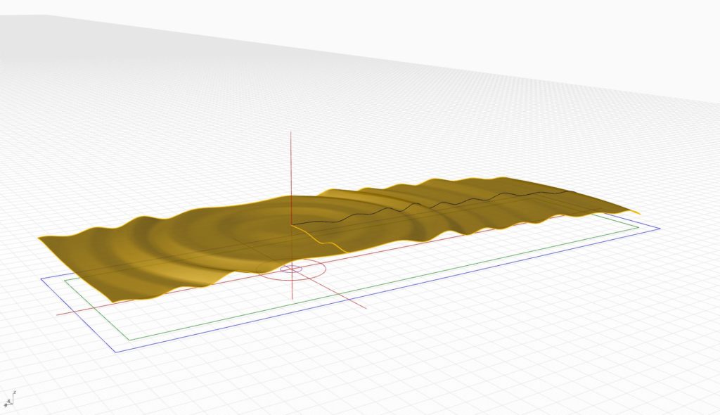
Here’s the view of the trim result from the side.
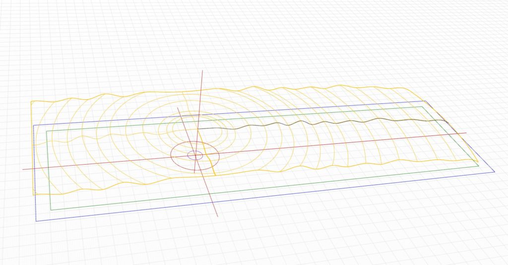
And, a better view yet when I only show the outlines. Note how that vertical center line goes right through the new ripple surface to the center point of my original 2D line.
Now that I have the base area for the ripple, I need to extrude the vise’s outside shape (the purple line) like I did in the last post.
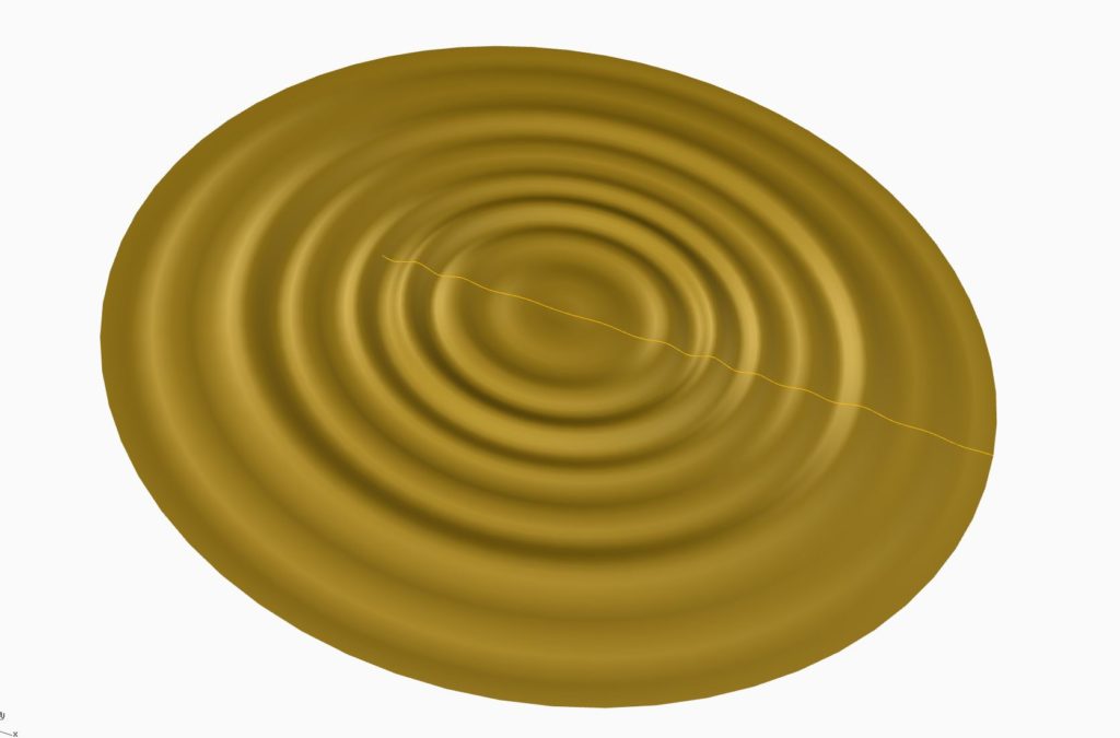
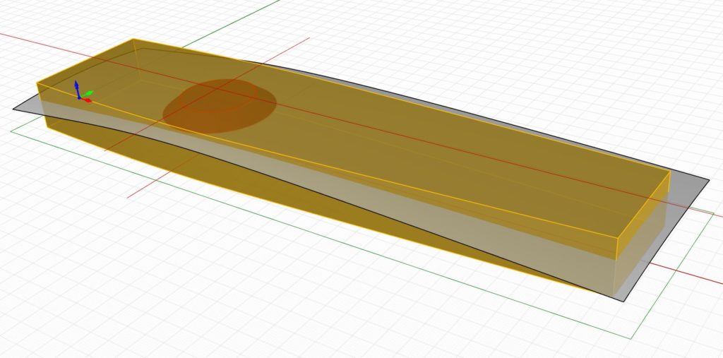
Overlaying the surface with the extruded vise shape looks like this earlier example. I just trim off the excess from the oversized ripple surface I just created.
Once you clean everything up, here’s the final result.
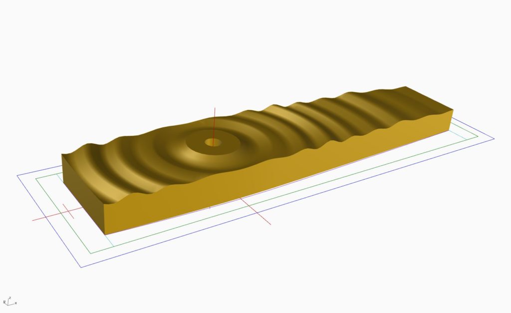
That’s the basics of creating a three-dimensional surface for a leg vise chop. Essentially, I create a surface texture or pattern, I warp it onto the smooth curved surface, as I demonstrated in my last post and then I trim it.
In upcoming posts, I’ll take you on a quick tour of the 10 different designs and show you the results. Later, I’ll explain how the vise chops were machined on a CNC.
Additional Resources
- All posts on the BARN workbench click here.
- Photos of the BARN workbench chops click here.
- A video about how the chops were made click here
- Additional Digital Woodworking videos click here.
Here are some supplies and tools we find essential in our everyday work around the shop. We may receive a commission from sales referred by our links; however, we have carefully selected these products for their usefulness and quality.