<img height="1" width="1" style="display:none" src="https://www.facebook.com/tr?id=376816859356052&amp;ev=PageView&amp;noscript=1">
 In Projects, Shop Blog, Techniques

We may receive a commission when you use our affiliate links. However, this does not impact our recommendations.

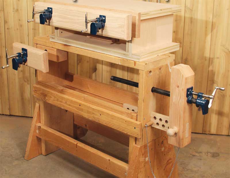
3 Classic Vises made with Pipe Clamps

Increase your
bench’s versatility
on a budget.

By Chad Stanton

As a professional woodworker,
leaving the comfort of my
shop to work on a jobsite is part
of the routine. I always take along
a portable bench that’s equipped
with three inexpensive vises made
with pipe clamps. They’re durable
and simple to operate. To build
them, all you need is some plywood
and construction lumber. Almost
any brand of pipe clamp will work.
These vises can also be adapted to
fit a larger, stationary bench, too.

Face vise.
The face vise is the workhorse of
any bench. It’s usually the first—and
sometimes the only—vise woodworkers
buy. Typically, it holds boards so their
edges can be worked.

Click any image to view a larger version.

Tail vise.
The tail vise, typically used in conjunction
with bench dogs, is used for holding parts
flat for face work. Mine has an adjustable
guide board, similar to a leg vise. The guide
board keeps the jaw from spinning and
enables the vise to hold
large workpieces.

Moxon vise. The Moxon vise is essentially a face vise
with two screws. Because it clamps to your
bench top, it brings your work closer to eye
level—a dovetailer’s dream. My design also
features a quick-release handle.

Face Vise

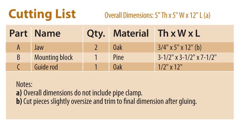
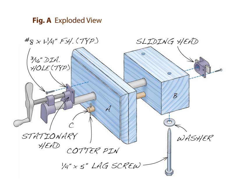
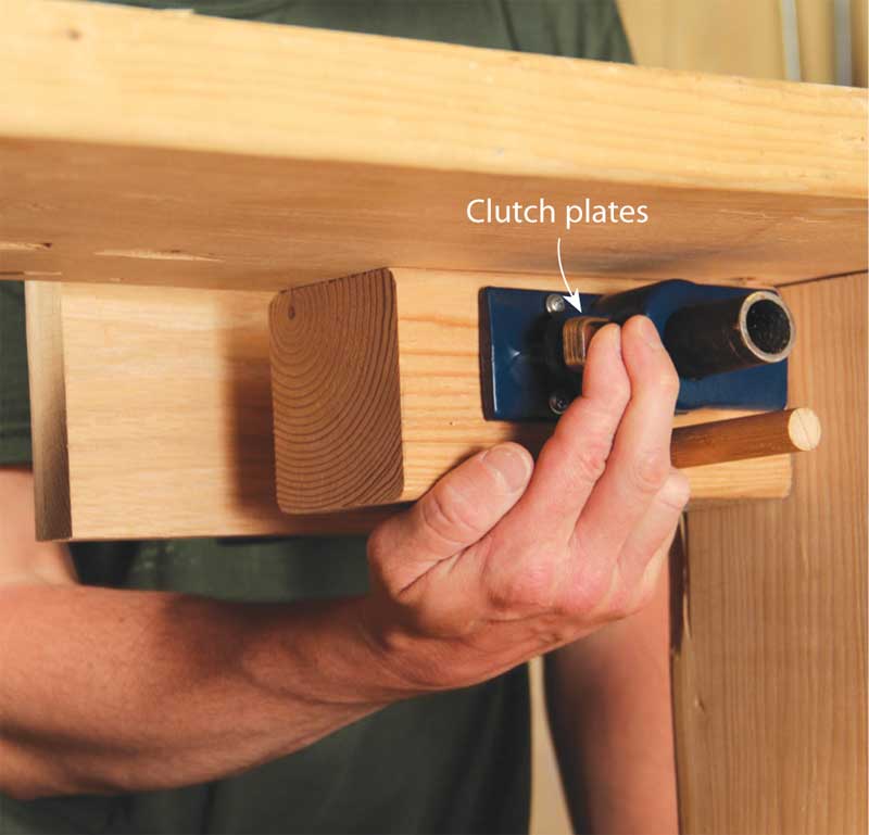
This is the simplest and most-used vise of the three. You can
use whatever length pipe you like, but I find that a pipe about
14" long is sufficient for most tasks (Fig. A).

Cut the jaw’s pieces (A) slightly oversize, so you can true up
the edges aft er gluing them together. Two pieces of hardwood,
such as oak, make for a stiff , rugged jaw. I rounded over the
jaw’s outer edges, but that’s optional.

To drill the vise’s holes, temporarily screw or nail the mounting
block (B) to the jaw’s back side. Make sure the mounting
block is positioned so that when the vise is installed, the jaw’s
top edge will be flush with the bench’s top.

Use a drill press to drill the holes for the pipe and guide rod
(C) through both the jaw and the mounting block (Fig. B). Th e
guide rod prevents the jaw from spinning. Next, separate the
mounting block and jaw, and drill the lag screw holes in the
mounting block. Using a metal-cutting bit, drill holes in your
clamp’s sliding head and the jaw of the stationary head.

To mount the vise to your bench, clamp the mounting
block under your bench’s top, flush with the bench’s front edge,
and then fasten it with lag screws.

With the clamp’s sliding head removed, insert the pipe and
guide rod through the jaw and mounting block. Reinstall the
sliding head and then tighten the clamp on the two parts, with
the stationary head positioned vertically and the sliding head
positioned horizontally. Along with the mounting block’s relatively
short length, the sliding head’s horizontal position makes
the clutch plates easy to reach. Fasten the heads to the jaw and
mounting block using screws, and secure the guide rod with a
cotter pin.

To adjust the vise, reach to the back of the mounting block
to squeeze the clutch plates. Slide the jaw into position and
tighten using the clamp’s handle.

Cutting List

Fig. A: Exploded View

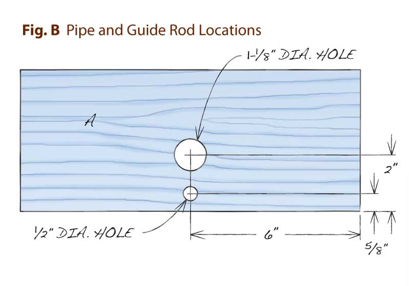
Fig. B: Pipe and Guide Rod Locations

Squeeze the pipe clamp’s clutch plates to adjust the jaw in
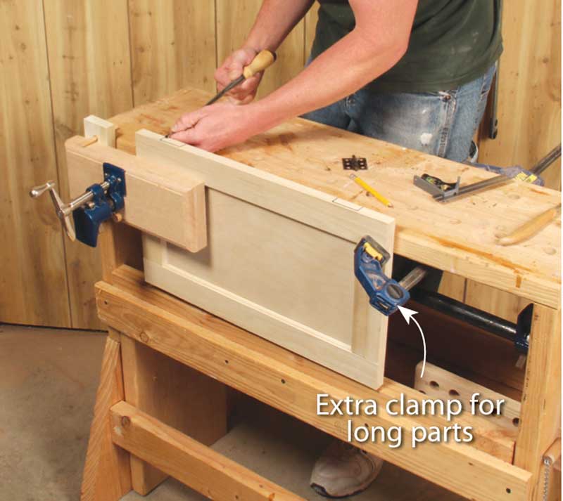
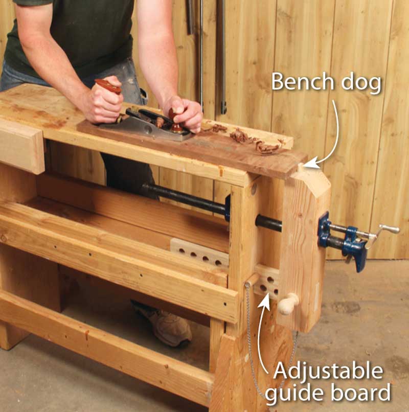
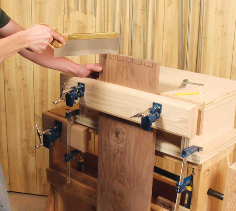
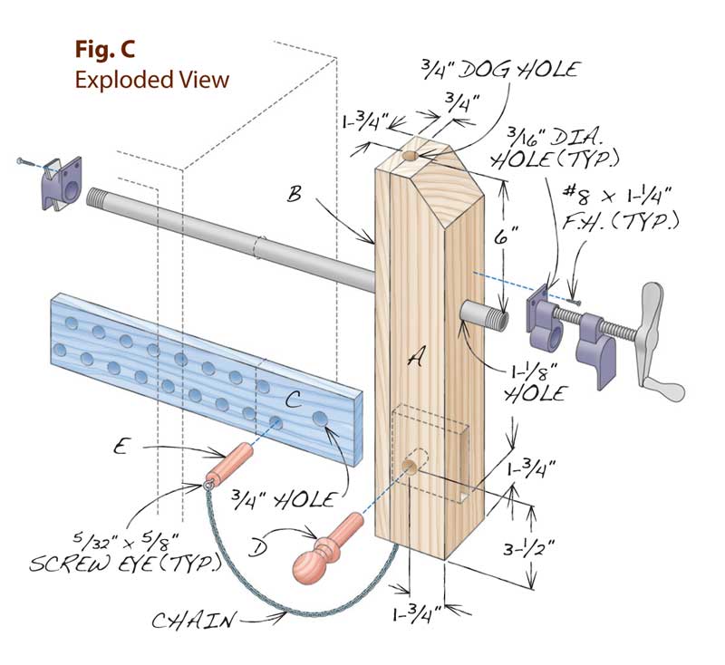
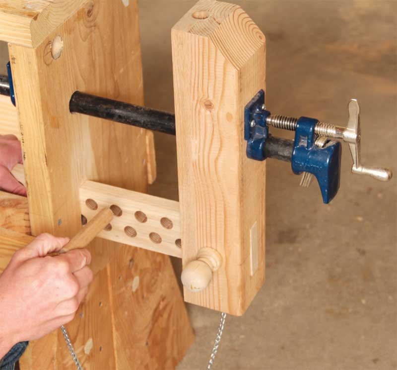
or out to suit the size of your workpiece.

Tail Vise

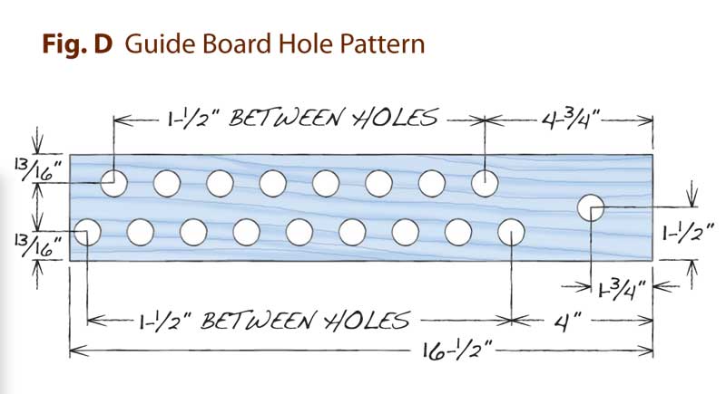
Like the face vise, first glue up the jaw (A) and faceplate
(B) assembly. You could probably get by without the faceplate,
but a stout wood like oak stands up to hard use much better
than pine. Square up the assembly using a jointer and planer, if
available. If not, a tablesaw or circular saw will do.

Mark and drill the jaw’s pipe hole using a drill press. Also
drill out the mortise for the guide board (C). A Forstner bit
works best for this, because it lets you overlap the holes. Clean
up the mortise’s cheeks using a chisel.

Clamp the jaw in position to your bench’s end. Using the
pipe hole and mortise you just made as guides, mark the hole
and mortise on the bench’s leg.

Use a hand drill to make the pipe hole through the bench’s
leg and to excavate most of the leg’s mortise. As before, clean
up the mortise using a chisel. Make sure the pin board slides
freely through the leg’s mortise.

Drill the adjustment holes in the pin board (Fig. D).
Insert the pin board in the jaw’s mortise and, on the drill
press, drill the hole for the knockdown pin (D). Assemble
the two parts. Th e knockdown pin makes full disassembly
easy for transport. I added a wooden knob to my pin to make
it easier to remove.

Drill screw holes in the clamp heads. Insert the pipe into
the jaw and slide the assembly into position on the bench.
Reinstall the sliding head, tighten the clamp and install the
clamp head mounting screws.

Drill the dog hole in the jaw’s top, and a series of holes in
line with it on your bench’s top.

Use the adjustment pin (E) to set the vise’s opening according
to your workpiece’s size. I fastened my adjustment pin to
the jaw using screw eyes and a light chain, so it doesn’t get lost.

I used a 16" pipe for this vise. Like the face vise, reach under
the bench and squeeze the clutch plates to adjust the clamp.

Cutting List

Fig. C: Exploded View

Fig. D: Guide Board Hole Pattern

Insert the adjustment pin in the hole that gives you the
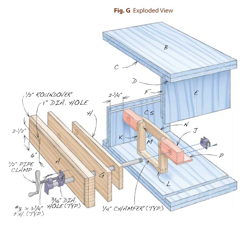
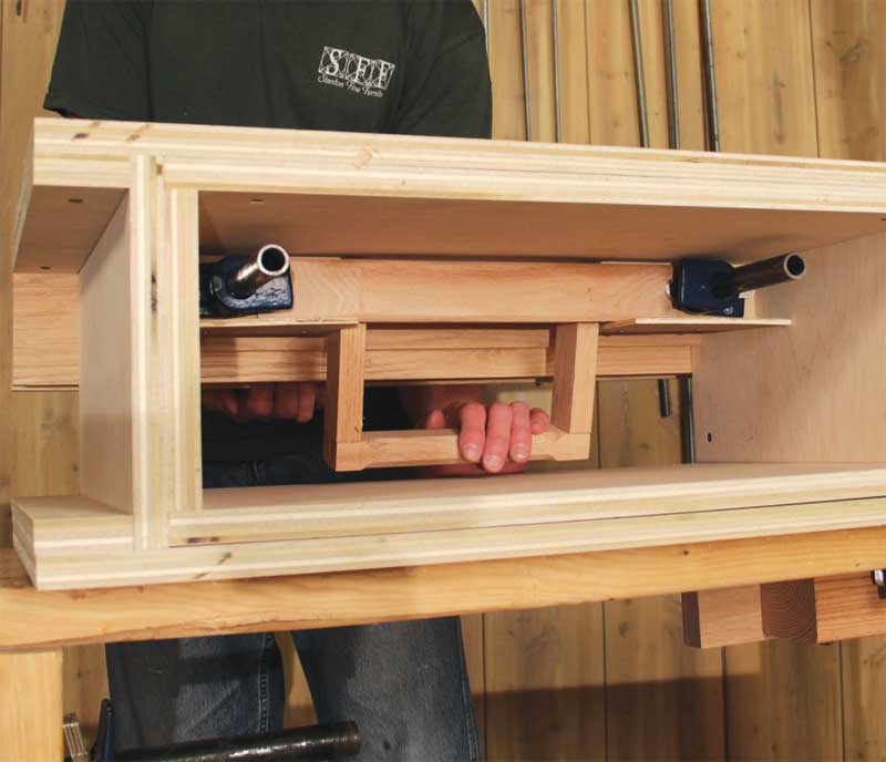
jaw opening best suited to your workpiece. Adjust the pipe
clamp by squeezing the clutch plates to release their grip.

Moxon Vise

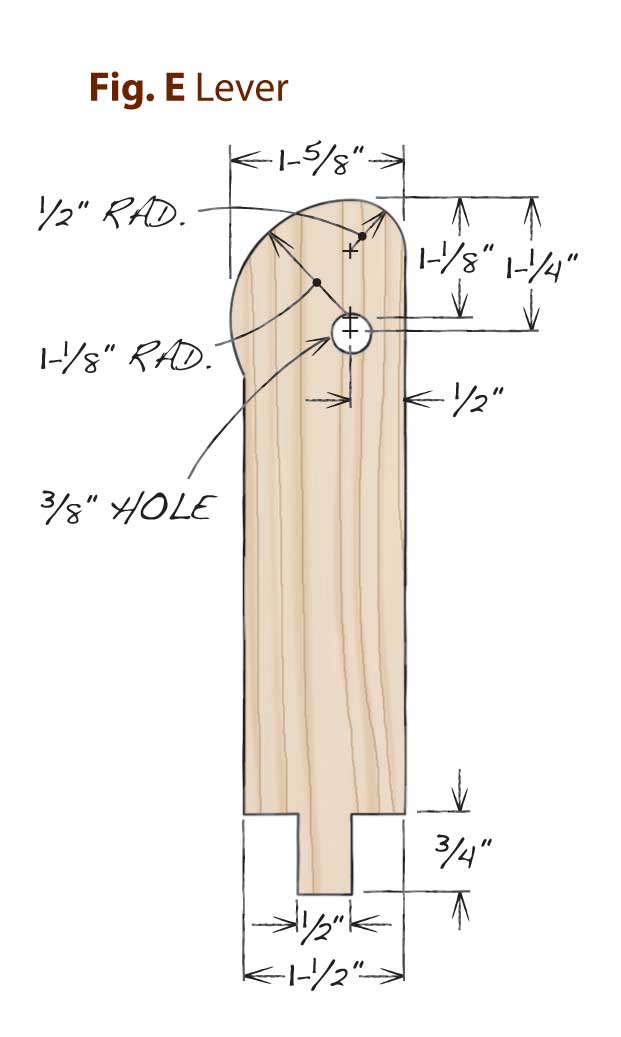
Named after 17th-century woodworker and author
Joseph Moxon, this vise specializes in securely holding
wide boards. Two clamps provide even clamping pressure
across the whole board with no racking. Th e main feature
my version has that the original didn’t is a quick-release
mechanism (Fig. G and photo below).

Another benefit of the Moxon vise is its height. It
clamps to your bench’s top, so your work is at about chest
height. When you need to be close to your work, such as
when cutting dovetails, this is the vise to use.

Unlike the other vises, I used 1/2" instead of 3/4" pipe
clamps. Half-inch pipe clamps provide all the holding power
I need, and I saved a few bucks. The pipes are 12" long.

A good vise must be extremely stable. I made this one
extra-beefy, since it isn’t actually attached to a bench.
Using two thicknesses of 3/4" plywood allowed me to
make deep, strong, rabbeted dado joints without having
to actually cut dadoes.

To build the vise, glue up the front jaw pieces (A)
and set the assembly aside. Meanwhile, assemble the
top and bottom (B), including the buildup (C) and filler
(D) pieces. Use a plywood off cut as a spacer to create the
dadoes. Trim the front jaw to final size and round over
the outer edges if you wish.

Glue and screw the outer and inner sides (E and F) in
place. Turn the assembly upside down and position the
front jaw, rear jaw (G), rear jaw buildup (H), and guide
blocks (J).

Mark and drill the front jaw holes using a drill press
and then reposition the front jaw on the assembly. Slide
the drill bit into the jaw’s holes to mark the hole centers
on the rear jaw. Mark and drill the rest of the jaw/guide
block assembly in the same manner. Finally, drill the
holes in the ends of the guide blocks (Fig. F).

Next, cut out the levers (K, Fig. E) and handle (L).
Mark the levers’ radii before drilling their holes. If you
drill the holes first, you won’t have a place to position
your compass for drawing the larger radius. Drill the
holes in the levers, cut the bridle joints, chamfer the handle
and glue the dowels (M) in the levers.

After the glue dries, slide the guide blocks onto the dowels
(do not glue) and screw the whole assembly in place.

Before attaching the bottom, assemble the vise as
you did the other vises, by removing the sliding heads
and inserting the pipes through the jaw assembly. Set
the push bar (N, Fig. H) in place and make sure the
sliding heads are oriented properly before screwing them
to the guide blocks. Th ere should be about 1/16" of play
between the push bar ends and the clamps’ clutch plates.
Adjust your push bar’s ends as needed to fit behind your
clamp’s clutch plates.

Install the push bar retainers (P) and test the handle’s operation.
Lastly, attach the bottom using glue and screws.

Cutting List

Fig. E: Lever

Fig. F: Guide Block End Hole

Fig. G: Exploded View

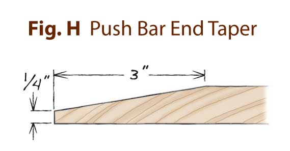
Fig. H: Push Bar End Taper

Pull the handle towards you to release the clutch plates for
quick adjustment of the front jaw.

This story originally appeared in American Woodworker August/September 2013, issue #167.


Product Recommendations

Here are some supplies and tools we find essential in our everyday work around the shop. We may receive a commission from sales referred by our links; however, we have carefully selected these products for their usefulness and quality.

Recommended Posts

Start typing and press Enter to search