We may receive a commission when you use our affiliate links. However, this does not impact our recommendations.
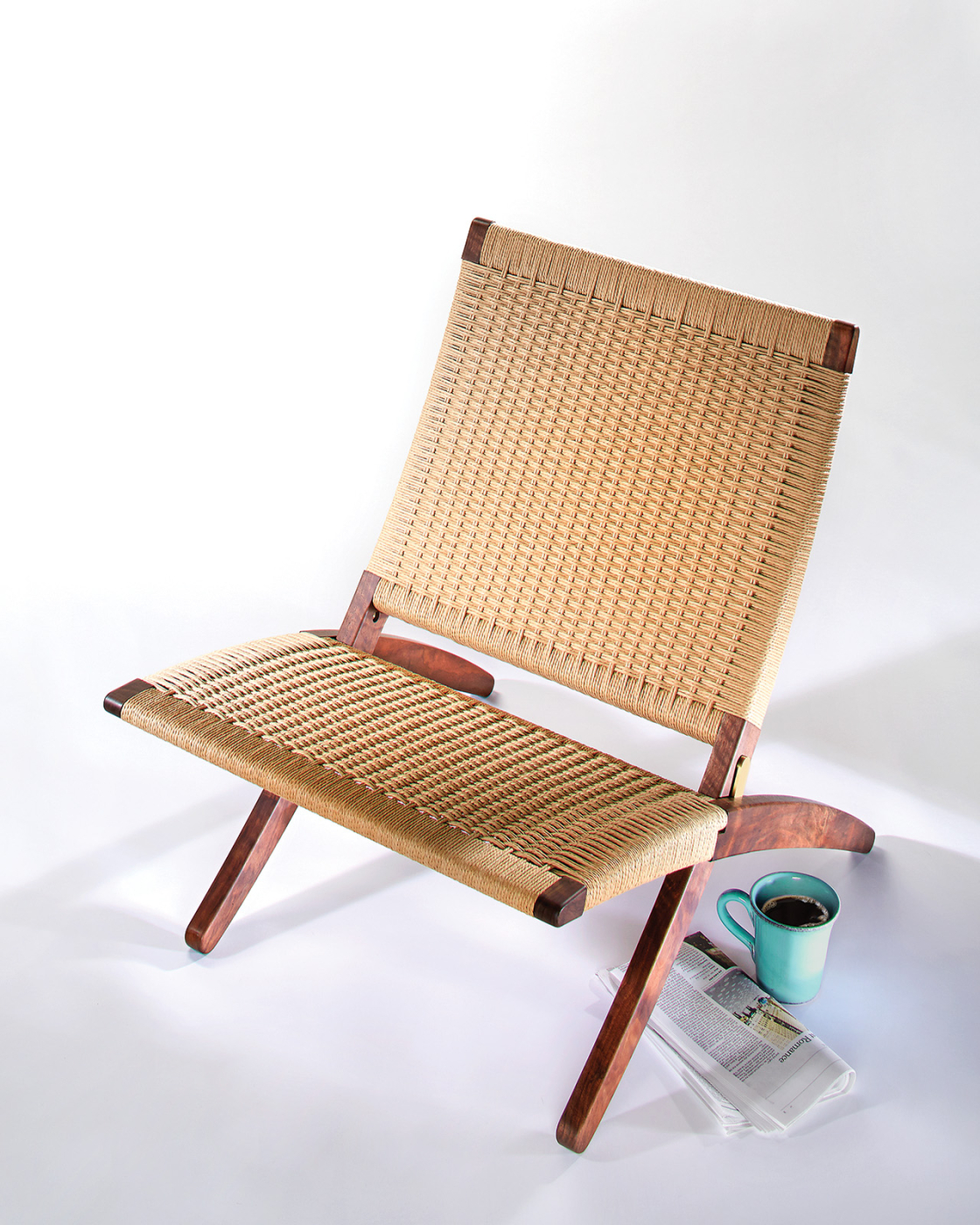 Shop-made hardware and precision joinery are the foundation for this Danish-inspired folding seat.
Weave the seat: Paper Cord Weaving
Download: LoungeChairPlans PDF
Danish furniture is making a comeback these days. It’s been a favorite of mine from the moment I discovered the style. It had all the hallmarks I wanted in furniture: simple, beautiful design and construction. Nothing fancy, just good, honest furniture I could put to use that would stand the test of time and only look better with age. I loved Shaker and Arts & Crafts furniture and, unknown to me at the time, these styles had a huge influence on Danish designers.
 Hans Wegner set much of the tone for that era; his 512 folding lounge chair was one of his most imitated designs. Inspired by the Shakers – who hung chairs on the wall when not in use – this chair was to be stored on a wall hook and brought out when one needed extra seating for guests. It turned into permanent seating, however, for most owners.
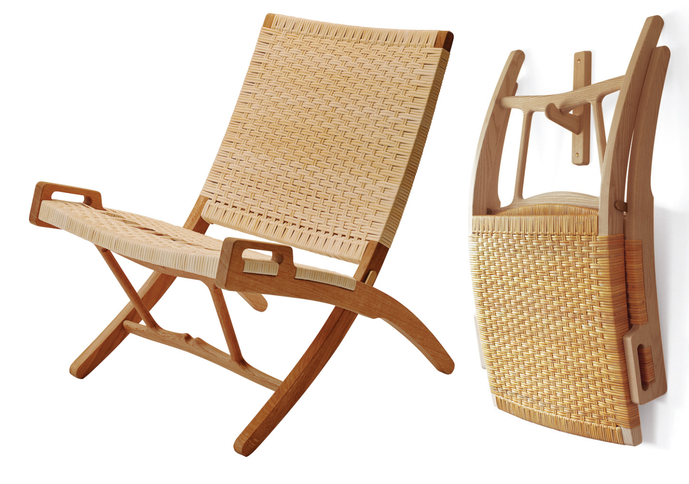
Classic. The folding lounge chair by Hans J. Wegner spawned a Danish classic that still fits right in the modern home – it’s still manufactured today, by PP Møbler (PP512)
The Danes didn’t seem to hold back from taking cues from one another when it came to designing a new piece. Many considered Wegner’s design to be influenced by Ludwig Mies van der Rohe’s Barcelona chair, which in turn was thought to be an extrapolated form of the Grecian Klismos chair and/or the Roman Curule chair. The roots of the Danish folding lounge chair do indeed even reach back to the classical forms.
I designed a chair that incorporates the classic folding chair of the Danes and their love of paper cord as a weaving material. If you have ever wanted to learn how to weave Wegner’s CH25 lounge chair, this is virtually the same pattern. I hope you enjoy building my version of a Danish classic and make it a classic in your home.
Hardware Money Can’t Buy
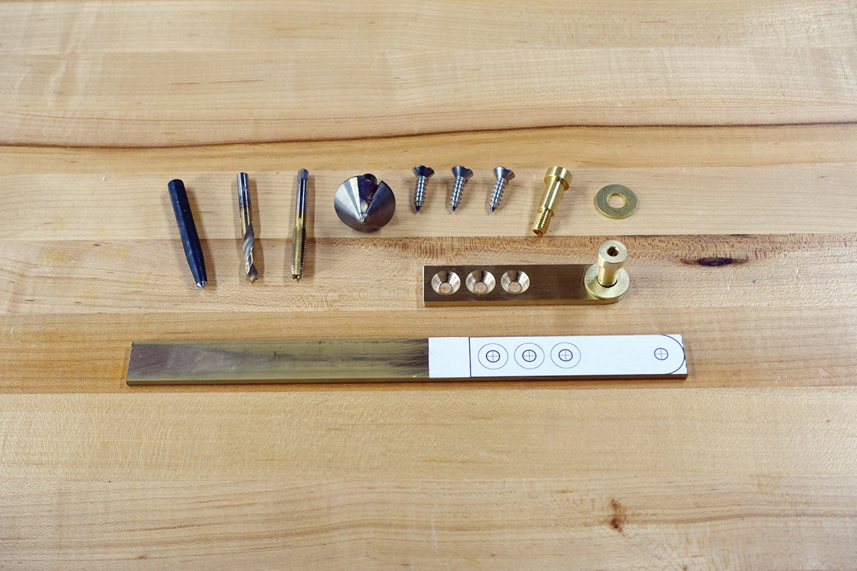
When you can’t buy it… Here’s all you need to make the hinge hardware: brass bar stock, a punch,1⁄4″ drill bit, 5⁄16″-18 tap. countersink, #14 1″ screws, brass shoulder screw and brass washers.
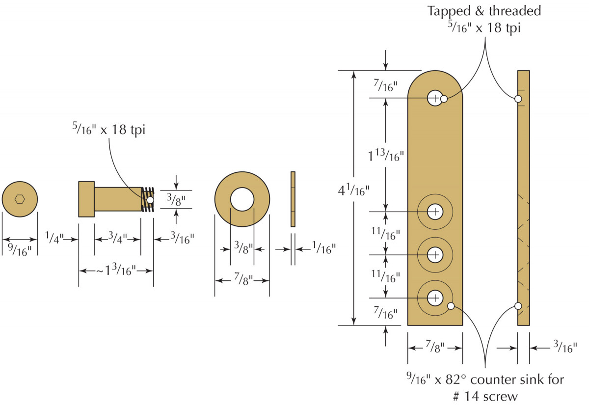
The heart of this chair lies in its foldability. This hinge hardware isn’t off-the-shelf stuff; make your own – it’s much easier than you think. It starts with some flat brass bar stock 7⁄8” x 3⁄16” x 41⁄16” per hinge. It’s about as easy as drilling four 1⁄4” holes and tapping one to accept 5⁄16“-18 threads. (A note of caution: Always securely clamp down brass when drilling; otherwise, a standard drill bit will grab and send the stock spiraling with the bit. Not pretty.) The other three holes need to be countersunk for a standard 82˚ wood screw head.
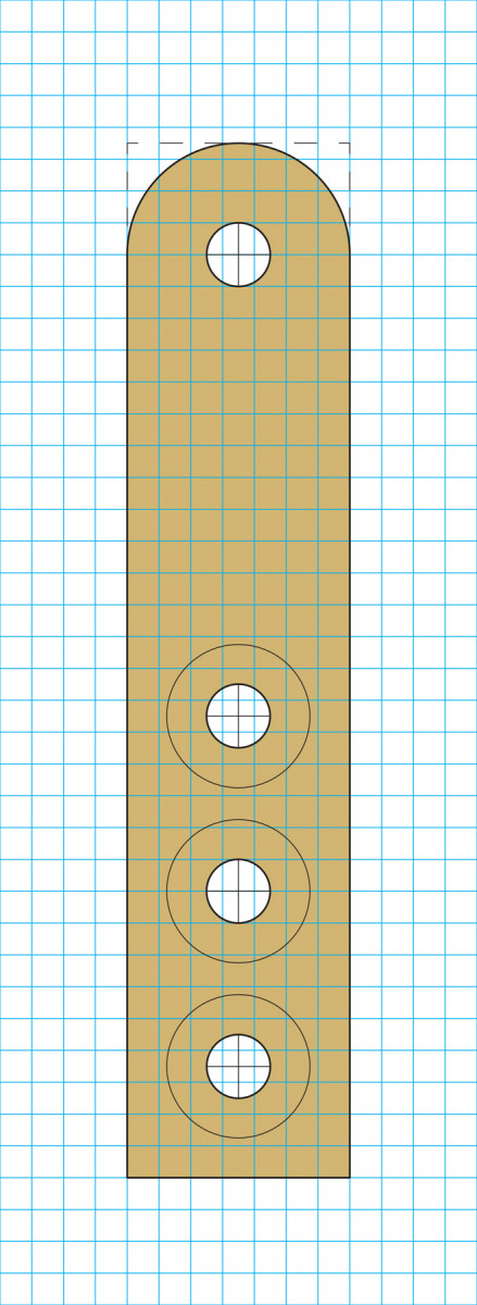
Hinge leaf pattern Shown at full size One square = 1⁄8″
Use the hinge pattern above and directly adhere it to the brass with some spray adhesive. Let the brass extend slightly beyond the pattern. Center punch the drill points and get to drilling. Countersink the lower three holes so that a #14 screw sits slightly below the surface. Thread the upper hole for the shoulder screw. To make sure the threads are square to the brass bar, I do this with the tap mounted in my drill press. Lower the tap while turning the chuck manually by hand.
 The shoulder screw threads will extend beyond the opposite face of the bar stock so this will need to be trimmed flush. Saw off the excess with a hacksaw. Flatten this side with some #80-grit sandpaper adhered to a flat surface such as a granite surface plate. Now install the washer on the shoulder screw as a reference to guide you in shaping the round end. Use a file or a powered sander to accomplish this. Finish all surfaces to #180 grit. Remove the screw and flatten the inner face and sides as well. Once I’ve finished all the surfaces, I put blue painter’s tape on the outer face to avoid scratching it up while fitting the hardware.
While you’re at it make a pair of seat support pins and weaving bars. The pins are made from 1⁄2” outside-diameter (OD) brass round rod stock cut to 1 3⁄4” in length. Chamfer the ends and use #180-grit sandpaper to give the sides a consistent surface finish. The weaving bars are 5⁄16” OD stainless steel round rod cut to 14″ lengths.
Frame, No Panel
That was easy. Adhere the pattern to ½” MDF, cut it out, tack it on, trim off the excess and rout with a pattern bit.
The body of the chair is just two frames hinged together. And rather than a wooden panel, you’ll fill in those frames with woven Danish paper cord.
To make this chair, download and print the patterns at full scale at a local print shop. Don’t “fit to page” – and bring a ruler to confirm they got it right. (Or, carefully draw them yourself, working from the gridded illustrations in the PDF)
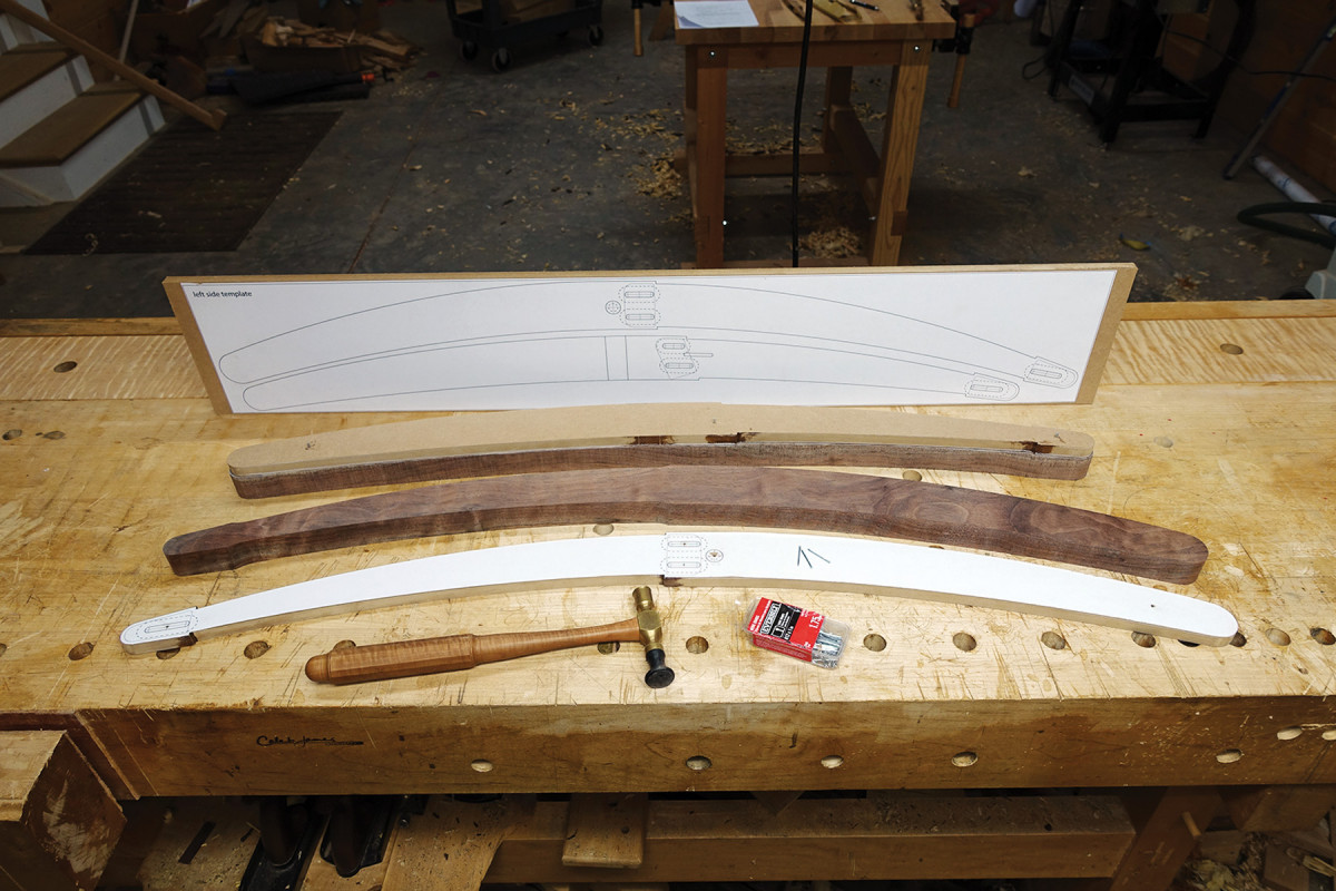
To start, make the curved sides of the frame. Using the side patterns, you have two options for how to go about doing this:
One is to simply adhere the patterns to the stock with spray adhesive, cut out the shape and refine with hand tools. If that’s your preference, work from both the right- and left-hand patterns through the steps that follow.
Or, if you prefer to use power tools, use one set of patterns to make a routing template and the other set for a mortising template – the method I use.
Adhere the pattern to 1⁄2” x 61⁄2” x 38″ MDF with spray adhesive. Cut out and shape the patterns as perfectly as possible. Any deviations will be reflected in every part you make, so take your time.
The side frames should be made in your primary wood choice. Here I’ve used walnut, but beech or white oak would certainly be in the Danish tradition. Select a rough board suitable for final dimensioning to 1 1⁄8” x 6 1⁄2” x 76″. Cut this in two 38″-long sections, which will make one side frame pair each.
There are a number of ways to adhere the routing patterns to the stock and it’s largely dependent on your particular setup.
I have a shaper cutterhead with segmented carbide inserts, thus I can rout all in one direction. My preference, therefore, is to simply drill 1⁄16” holes in the patterns at the mortise locations and tack them on with 1″ #17 finish nails, with the heads left proud for easy removal. One at each location will work, but also secure the end of the pattern where there is no mortise. If you don’t mind a hole as evidence of the manufacturing process, use the same nails or a pin nailer, or even double-sided tape.
Flip the patterns for the opposite side pair so you don’t end up with holes on the outside of one of your frame pairs. Trim the stock no more than 1⁄16” oversize to the pattern at the band saw. Now rout with a pattern bit (preferably at a router table).—CJ
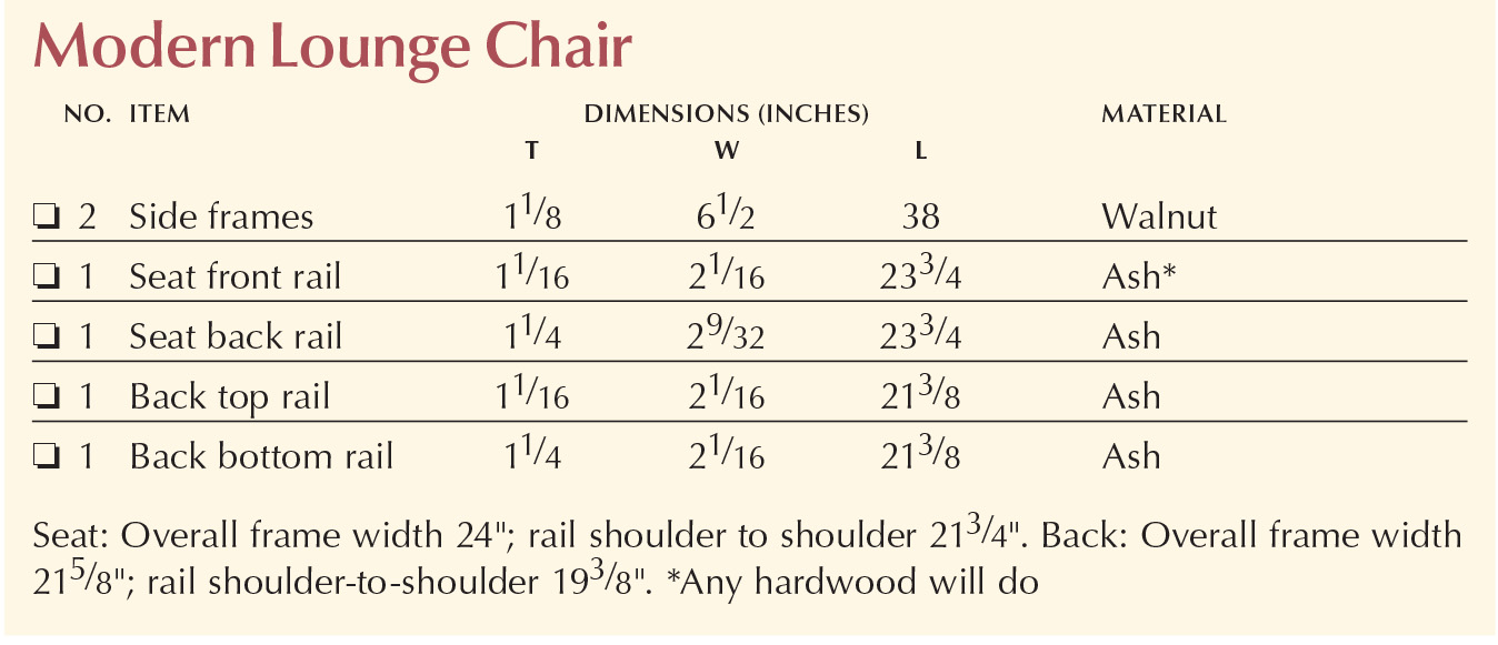
Modern Lounge Chair Cut List
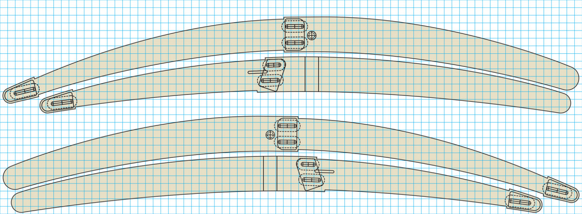
Side patterns One square = 1⁄2″
Hardware Meet Frame, Frame Meet Hardware
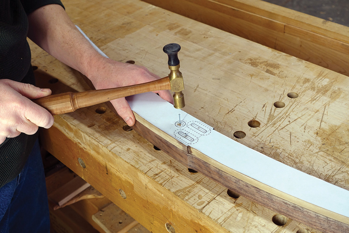
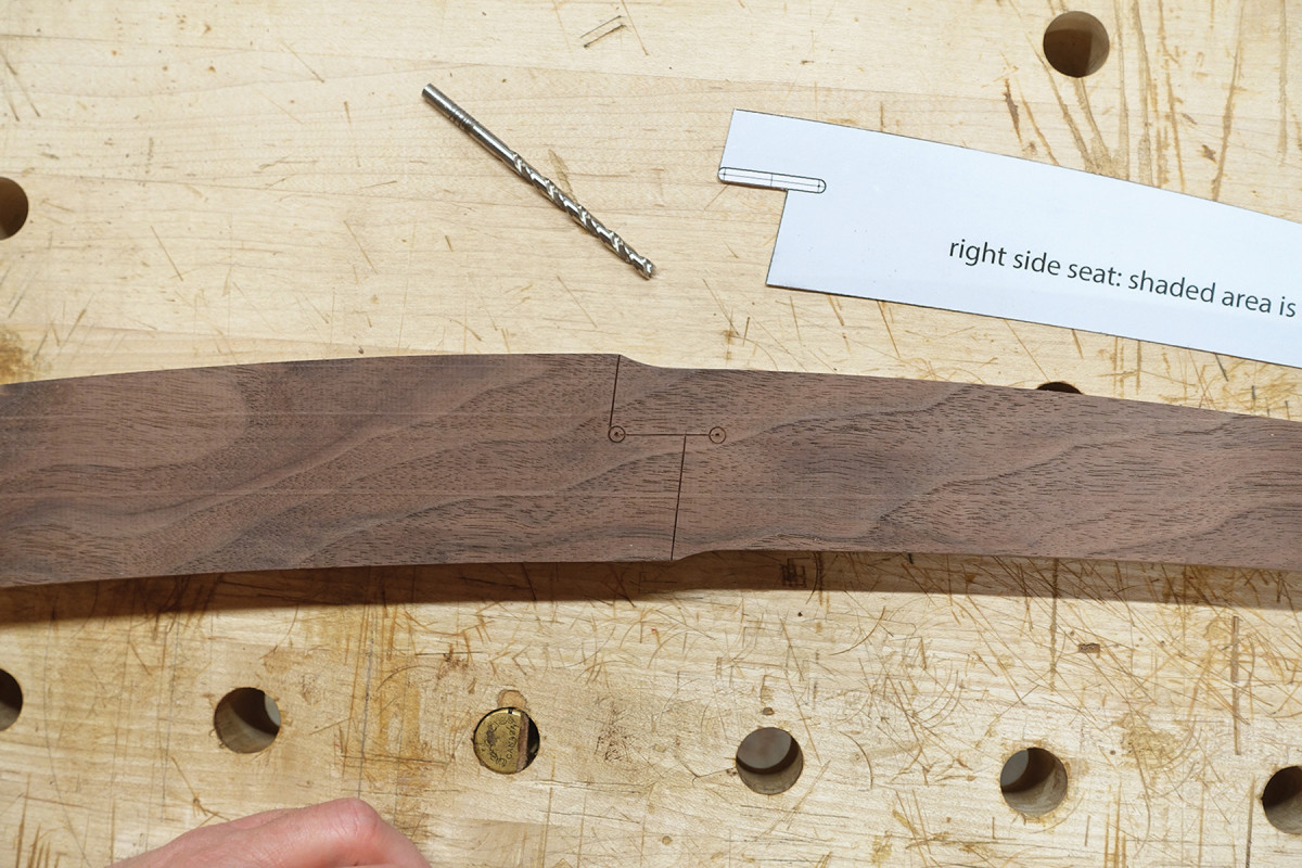
Before you go. Mark the center point of the hinge pin before removing the pattern.
For a properly functioning and long-lasting foldable chair you’ll need your hinge hardware tightly and accurately fit to your frame – there’s no room for “personal space” in this relationship. The backrest needs a hinge bolt hole drilled through its side while the seat frame needs a shallow dado for the hinge leaf to nest into. Careful transferring of these locations from the patterns to the parts is important.
For the backrest frame, transfer the center point for the hinge bolt onto the part. Because the pattern needs to be reversible, I drill a 1⁄16” hole in the pattern at the drill press to keep it dead square. I mark the center with the same nail as I tack the pattern on with. Once it’s marked, remove the pattern.
At the drill press, countersink a hole 1 5⁄32” deep with a 9⁄16” drill bit to match the screw head’s diameter. With the part still clamped in place, remove the bit and install a 3⁄8” bit and drill a through-hole for the shoulder of the screw. Do a practice run on scrap so you know you have the right clearance to remove one bit and install the other.
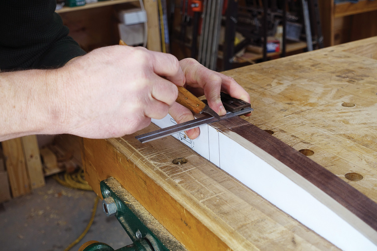
One more time. Transfer the hinge dado location before removing the pattern.
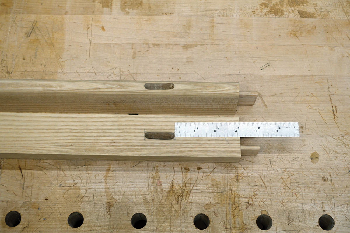
For the seat frame, transfer the hinge-leaf dado lines across the edge of the pattern onto the stock to the depth of the hinge (which is 3⁄16“). Do this on both edges. Then remove the pattern and connect one side of the dado lines.
Align your hinge hardware to this line and knife in a line on the opposite edge of the hinge to define the exact width. With a backsaw, carefully saw to the lines just as you would saw a tenon shoulder.
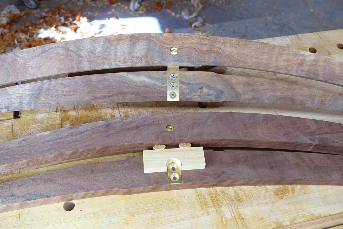
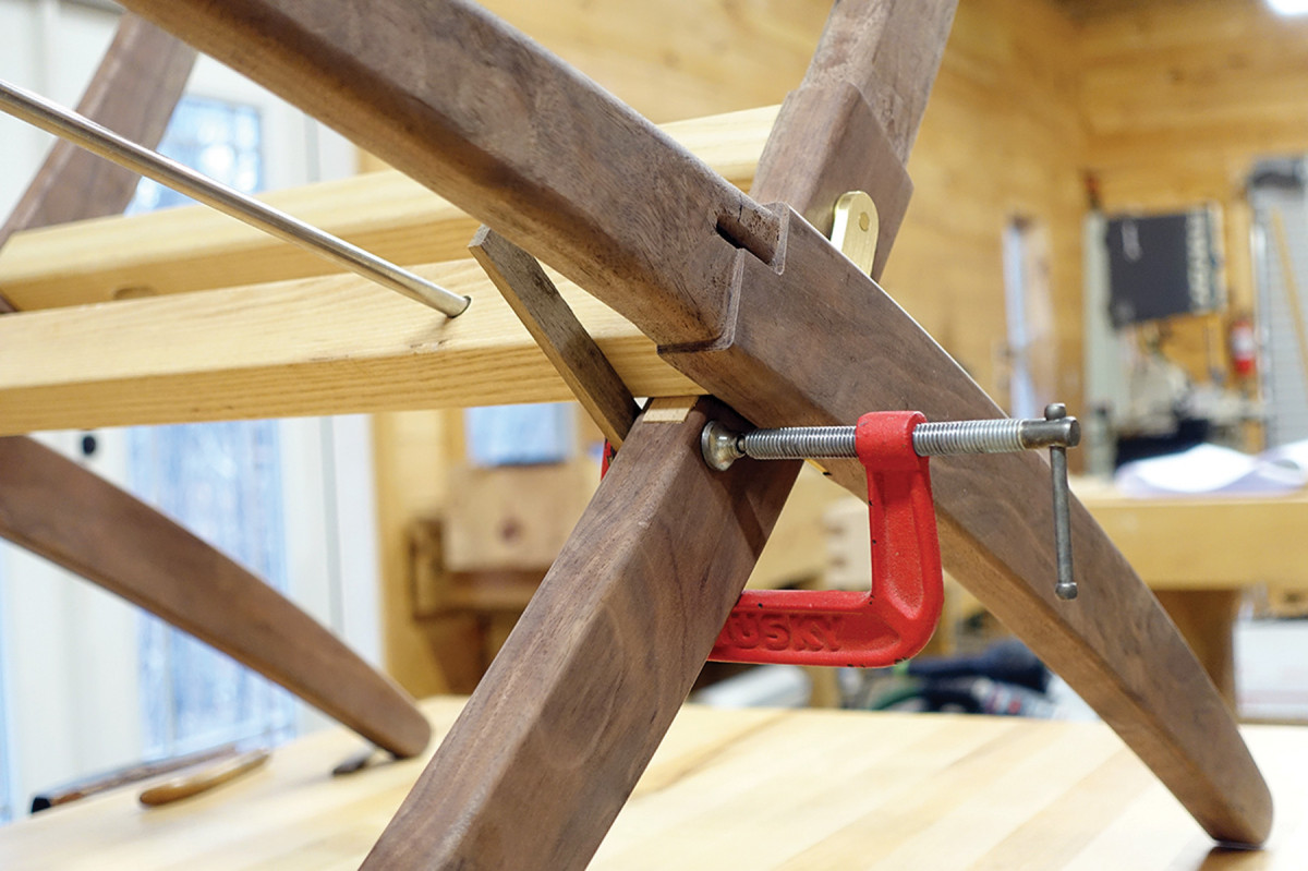
Consistent spacing is key. Make a spacer to maintain the correct distance between frame parts when installing the hinge hardware.
Excavate with a chisel, followed by a router plane, to level the bottom. Set the hinge leaf about 1⁄64” below the surface. Because much stress is exerted in this area, make the fit dead on. You don’t want any wiggle room, so take your time.
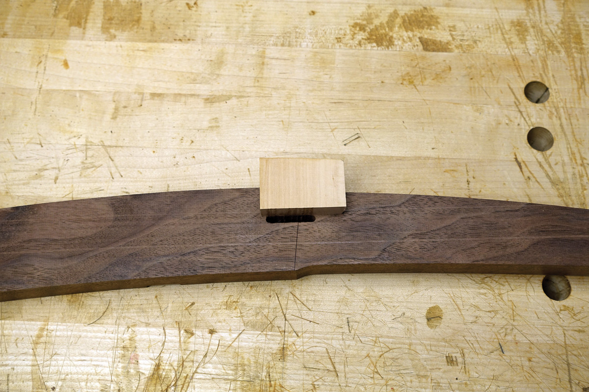
Spacered Out
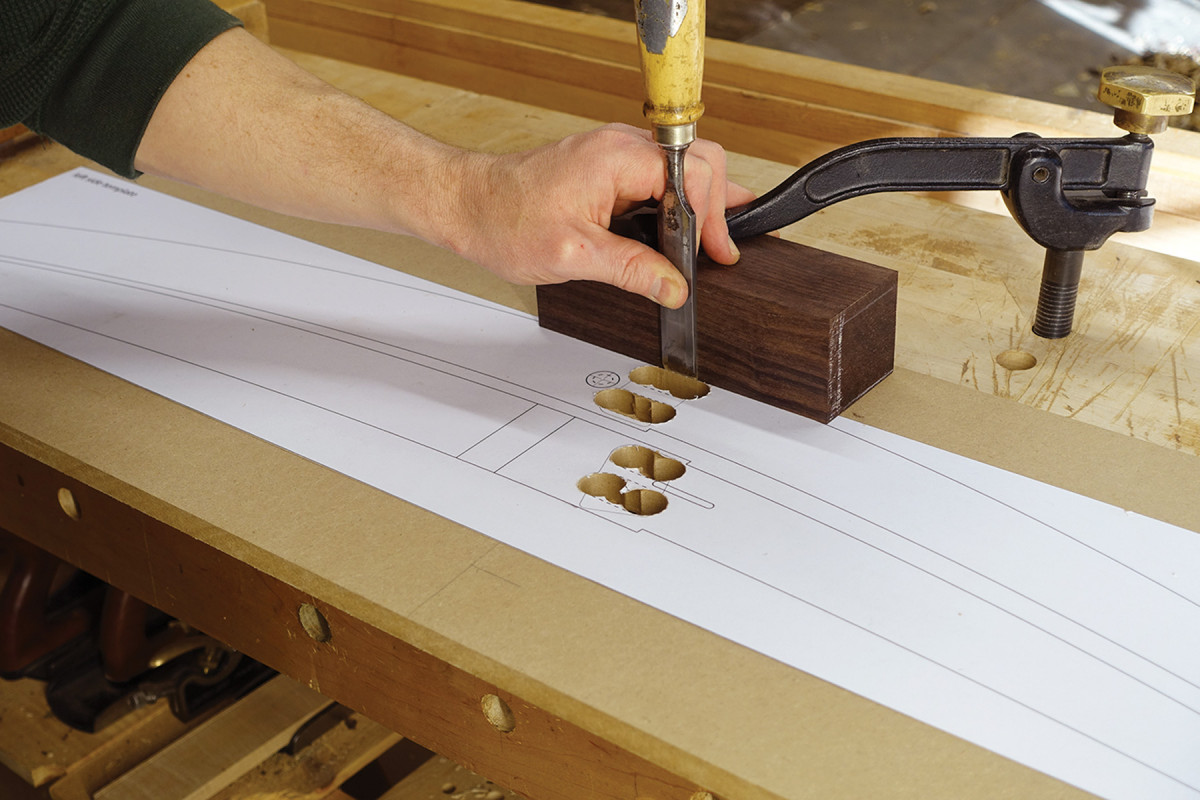
Let your block be your guide. Perfectly square is your aim, because the pattern will need to be reversible.
To make things work together properly you need a precise offset of 5⁄16” between the seat frame and backrest frame sides at the hinge location. To achieve this, make a 5⁄16“-thick spacer that straddles the hinge leaf.
Put the hinge bolt in the backrest frame side and mount the hinge leaf on the bolt. Set the hinge leaf in its corresponding dado.
With the spacer in place, mark the screw centers and drill pilot holes. I suggest doing one or two at a time in case you don’t get the center dead on. You can correct the hinge location slightly by offsetting the other pilot holes. Then remove the hardware and label each part to match its location.
Take the Plunge…Or Don’t
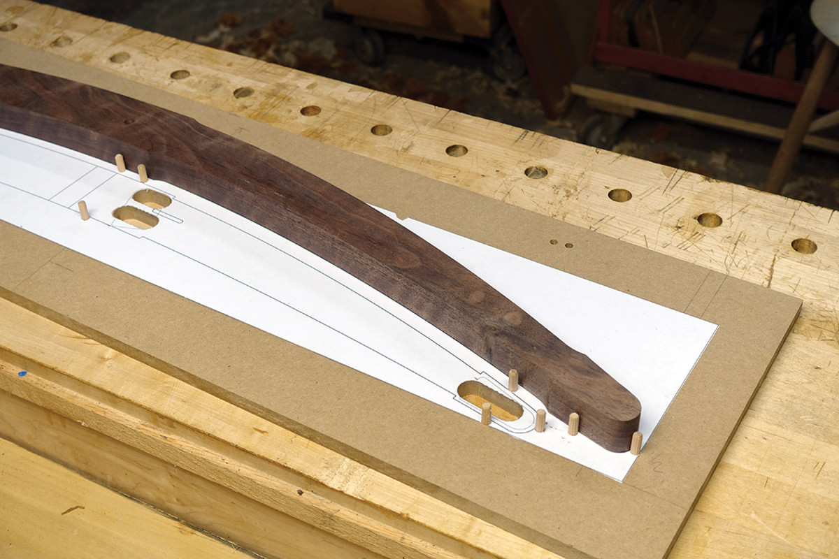
Like a rat in a cage. Let the dowel pins “trap” the part in place.
You’re ready to make your mortises. You’ll need a plunge router equipped with a 3⁄4” guide bushing and 1⁄4” upcut spiral bit.
Another approach is to use the router template patterns to transfer the center points of the mortise locations, then mark a centerline and drill out the mortise waste along it.
Using the second set of frame side patterns, make a template guide for your plunge router. Adhere this pattern to an oversized piece of 1⁄2“-thick MDF that measures approximately 11 1⁄2” x 41″ – this size provides plenty of support for the router.
Notice that the 1⁄4“-wide mortise locations on the pattern are outlined by a 3⁄4“-wide dashed line. This line is what the 3⁄4” guide bushing on the router will follow when making your mortises. Use a 3⁄4” Forstner bit to drill out both ends of this guide area. Using a smaller bit, drill out the waste in between. Then use a chisel along with a 90˚ guide block (to help keep your chisel perfectly vertical) to remove the remaining material. It’s critical to keep the walls vertical because the template will be reversed in use.
You’ll need to create some registration pins to align your side frame parts to this pattern. I use 1⁄4” dowels, but other sizes would work, too. Again, because this pattern will be reversed and must be dead-on, drill the registration pin holes at the drill press at locations close to what is shown below, center.
Plunge away. With the parts “trapped” in place, flip the workpiece over and clamp it down.
Initially, drill three registration pins on the pattern: one at the tip of each side frame and one above each mortise location at the frame edge. Register the side-frame part on the template against the pins and use the edge of the part to locate the exact locations for the remaining pins – one below each mortise and one at the opposite end at the “foot.” Now you should have a nice tight fit all around.
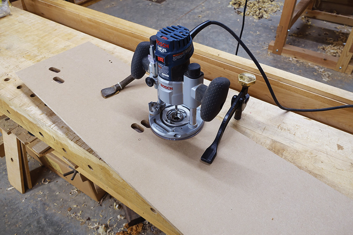
With your side frame parts in place, turn the workpiece over and clamp it to the benchtop. You’re ready to rout.
If your template slot has any play, make sure to keep the guide bushing pressed against the side nearest you. Now plunge a series of slightly overlapping holes at full depth from left to right. Then take one full-depth pass from right to left. This will give you a clean mortise with a consistent width.
To rout the opposite side, simply push the dowel pins through and flip the pattern over then repeat the process. The beauty here is that even if your template is slightly out of alignment, both sides of your frame parts will have the same error, thus virtually eliminating any twist in the final assembly.
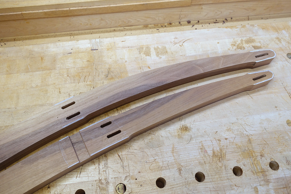
Paper Cord at Play
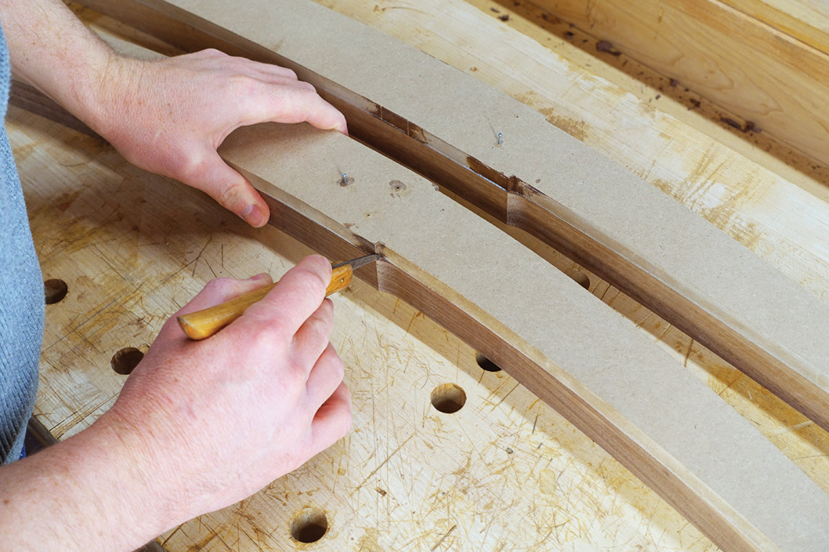
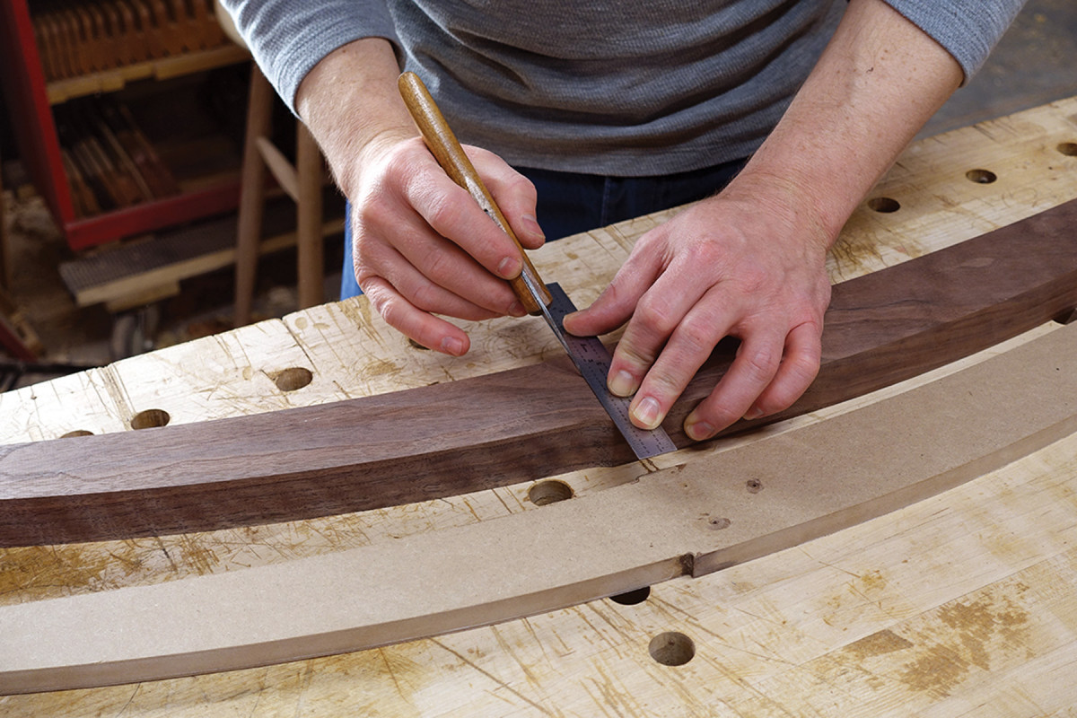
Boundary marks. Use your patterns to locate the boundaries of where the weave recessed area will stop.
Danish paper cord – the seat and back material in this chair – is most often recessed in such a way that the surrounding wood is approximately level with the cord. In other words, the paper cord is flush to the wood. Note that the edges of the frame patterns are already “notched out” to allow for this.
The sides of the frames need a corresponding 1⁄8“-deep recess. Using your routing pattern, transfer the locations of the “notches” on the side frame as shown in the photo at left to create boundary lines.
Connect some of the dots. Knife in the weave recess boundary lines on the backrest, but not on the seat just yet.
For the backrest, simply connect these marks with a knife to determine the boundaries of the recessed area on the frame sides. Now transfer these lines down each edge, registering your knife against a square.
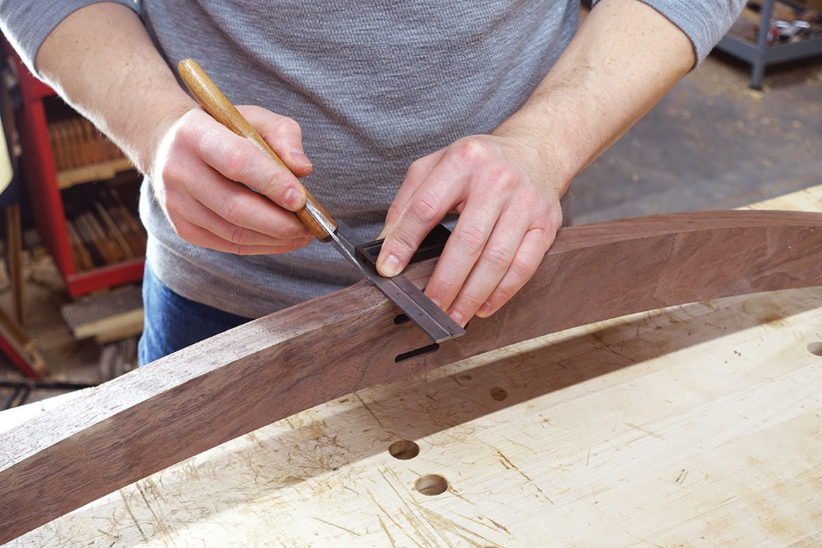
Then extend the lines down each edge, registering your knife on a straightedge.
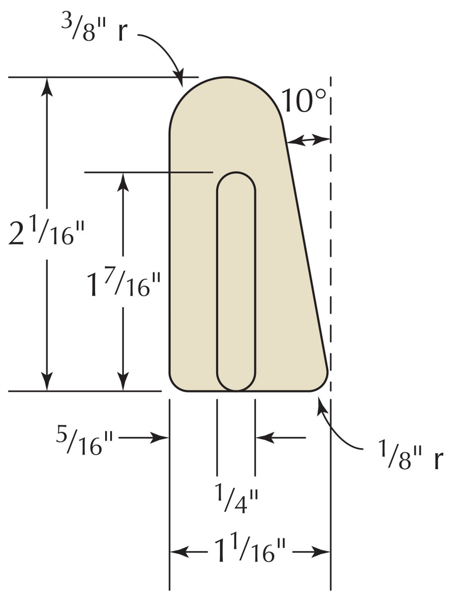
The seat frame is a bit more complex. Download and cut out the full-size seat pattern (or use a copier to enlarge by 200 percent the Seat Detail drawings below) for the paper cord weaving recess. I recommend adhering this pattern to card stock.
Align the pattern’s corners with the weaving boundary lines you marked from the routing pattern. Lightly knife in a line to mark off the boundaries of the recessed area. Using a straightedge, deepen the knife lines accordingly.
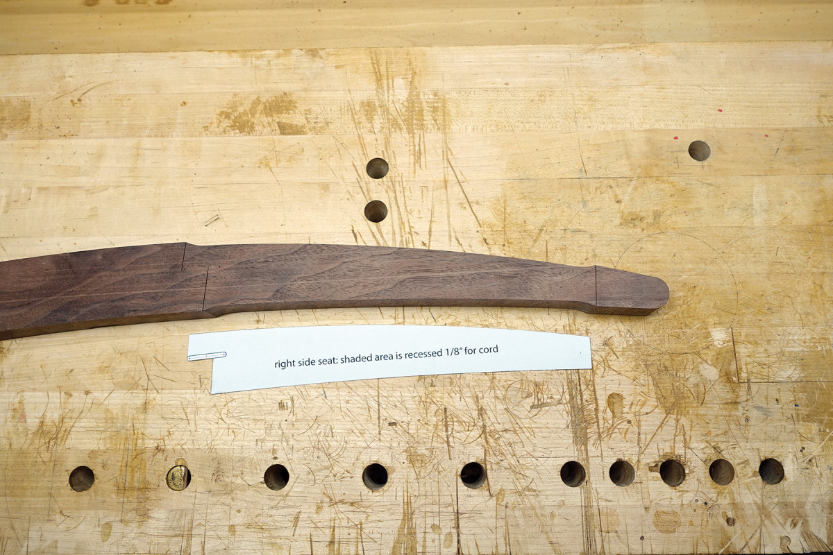
Inside the lines. The cord recess in the seat frame follows a specific pattern; mark it carefully.
The seat side frames need a 3⁄16” slot in the side for weaving through.
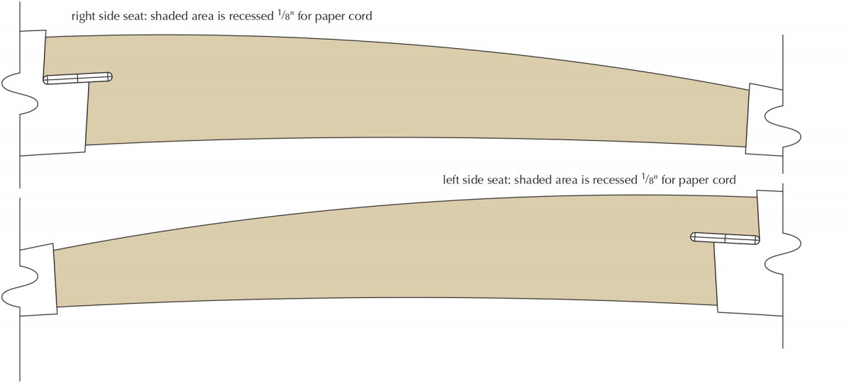
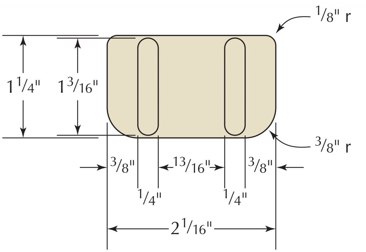
Seat Detail (shown at 50 percent)
Align the pattern with your boundary lines and prick the center points for both ends of the slot. Drill two 3⁄16” holes at the drill press. Align a small guide block with the edges of these holes and glue it in place with a couple drops of cyanoacrylate glue. Use this as a reference to drill a series of holes. Clean up the holes with a chisel. When you’re done, break off the block (easily done with a tap of a hammer).
Rounding the Bend
Prick & drill. After pricking the centers of both ends of the weaving slot, use a 3⁄16″ bit to drill two holes.
Don’t remove any material from the areas you defined just yet; leave it as support for routing. Most of the edges will be rounded over with a half-round router bit. The exceptions are where the cross rails meet the side frames; these areas must remain square because paper cord will butt against them once the chair is woven. The area 1″ back from the hinge dado up to the back seat rail is also left square. Using a 3⁄16“-radius roundover bit, rout all edges on both sides except the “no-go” areas on the insides of the frames.
Drill guide. Any scrap of hardwood with a square edge will give you a nice reference to drill out a straight slot.
Now you’re ready to remove the recessed material from the sides of the frames. Set up a 5⁄16“-radius roundover bit in the router table with its corner 1⁄8” above the table surface. Use a starting pin to pivot from, enter and exit the cut between the recessed weave boundary lines on the sides of the frames. This will simultaneously round over the edge of your weaving area and set the depth of the recess.
No go. Leave the areas marked in white untouched by the roundover bit.
To remove the bulk of the remainder of this material, set up a straight bit in the router table 1⁄8” above the table surface. Pivot off the starting pin to remove this material in a sweeping motion from right to left. Start near the end and work your way toward the middle of the frame, a little at a time.
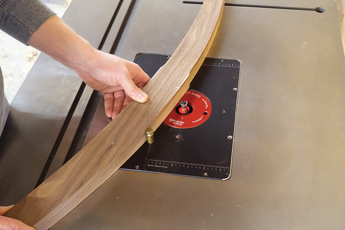
Controlled entry. Pivot off a starting pin at your router table to control the start and stop of the cuts.
What little waste remains can be removed with a saw and chisel. Saw down 1⁄8” at your cord boundary lines. A few additional crosscuts will aid in chiseling out the rest. Follow with a router plane for a consistent depth if needed.
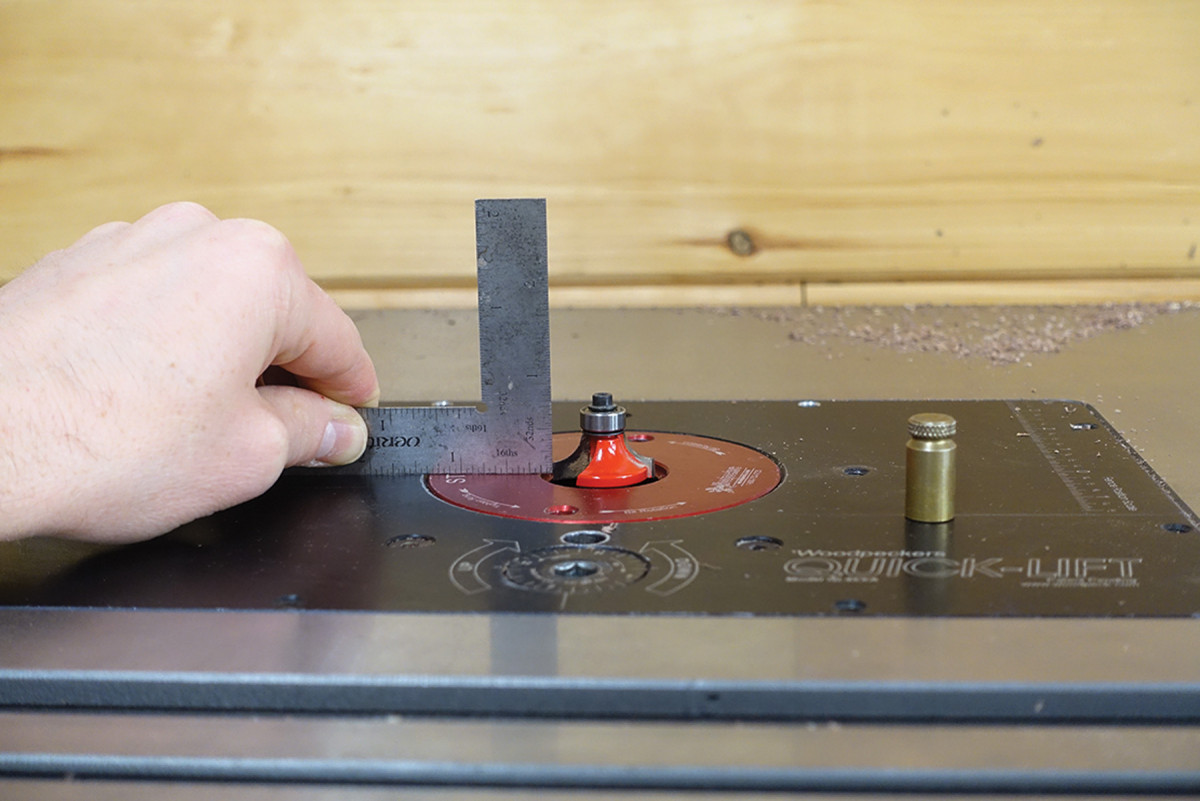
Critical depth. Set the corner edge 1⁄8″ above the table.
The inside corners of the recess along the edges of the frame need to be squared. Following the knife line you carried across the edge, saw and chisel out this bit of material.
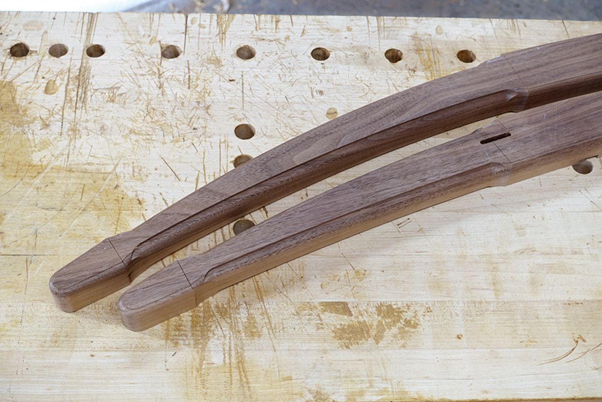
Two in one. Rout the cord-recess area to round over the edge and set the depth all in one go (you’ll remove the remaining rabbet waste with a straight bit). Stay between the weave boundary lines while routing.
There will be a square corner remaining that the 5⁄16” roundover bit didn’t reach. Use a rasp to round this area up to the inside corner of the recess.
Before you move on, ease the edge of the 3⁄16” weaving slot so that the cord won’t have a sharp edge to wrap around.
On the Rails
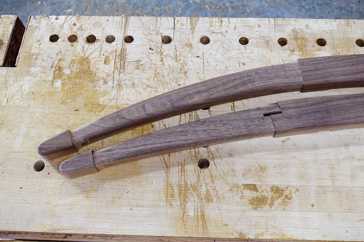
Level weaving field. After routing, remove the remaining material with saw and chisel. A rasp can help remove the material the roundover bit couldn’t reach in the corner.
Because the rails will be covered with paper cord and won’t show, you can use just about any hardwood for them. I typically use poplar, but I had some ash lying around that was just the right size so….
The rail at the front of the seat and the rail at the top of the backrest are the same except in length; the seat rail is longer. Dimension 5/4 lumber to 11⁄16” x 21⁄16“. The seat rail is 233⁄4” long; the backrest rail is 213⁄8“. The 1⁄4“-wide tenon is offset 5⁄16” from one face.
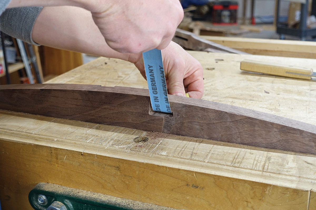
Ease up. Insert some cloth-backed sandpaper into the slot, and ease the top edge.
Mark out and saw these tenons as show in the drawing on page 31, making sure both ends have the tenon offset to the same side. Shape the edges of the tenons round with a rasp rather than squaring the mortises.
Fit the tenons to their frames while keeping the offset oriented according to the patterns. Note which tenon goes to which mortise, and mark it directly on the parts for future reference.
Measure twice, slot once…I mean twice. Shown here are the weaving slots for the top and bottom rail of the backrest.
It’s important that the tenons on both ends are coplanar, otherwise your frame will be twisted once it is assembled. I like to use a router plane to reference off one face of the stock to adjust the cheek of each tenon to the exact same plane. Then I adjust only the opposite cheek of each tenon to fit its mortise.
Cut a 10˚ bevel along one side per the drawing, but wait to round over the edges until all the rails are completed.
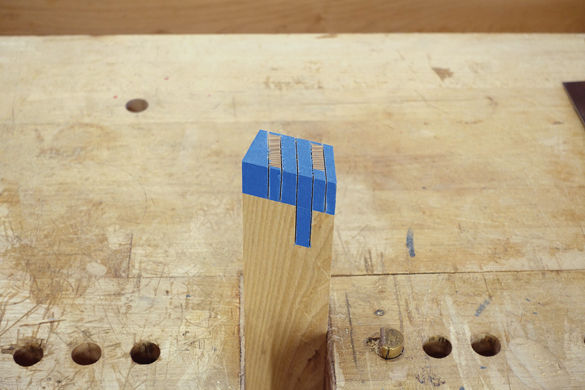
Saw the tenon & slot cheeks. The blue tape defines the waste material to remove.
The lower rail of the backrest is straightforward. Dimension 6/4 stock to 11⁄4” x 21⁄16” x 213⁄8“. Mark out and cut 1”-long tenons.
The top and bottom backrest rails need a weaving slot. Technically, it doesn’t matter which side these are on, but my measurements below are from the right side as if you are sitting in the chair. Measure 31⁄8” from the shoulder of the rail and mark out a 5⁄16” x 11⁄2” slot. This slot is centered front to back on the bottom rail. On the top rail, it is offset 3⁄8” from the unbeveled side. Drill out this slot and clean it up with a chisel, then ease the inside corners.
Cord shoulder. Short saw strokes and sawing at a steep angle will get you most of the way there in removing the cord pass-through waste. Clean up what’s left with a chisel.
Now that you’ve sharpened your sawing skills on the other rails, you’re ready to tackle the seat’s back rail. It’s a complex joint because it includes a weaving slot.
Dimension 6/4 stock to 1 1⁄4” x 2 9⁄32” x 23 3⁄4“. Cut a 21˚ bevel along one edge as shown in the Rear Sear Rail Profile drawing (next page). Using this beveled side as a reference face, mark off the tenon locations. I use a marking gage with a double cutter set to the exact width of my tenon; I find marking two measurements to be more accurate than marking four measurements.
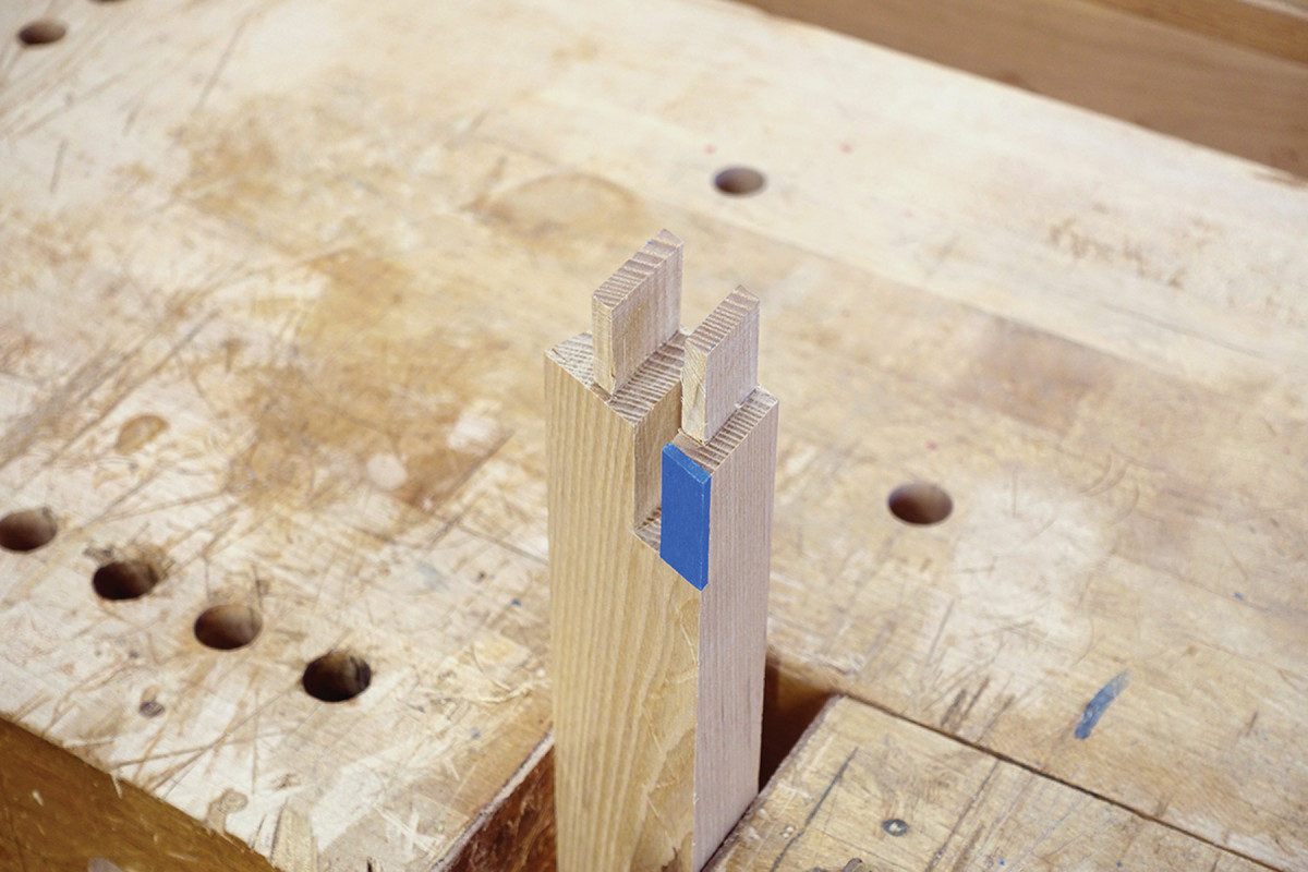
Step by step. The joint looks complicated, but approach it in steps and it’s actually quite easy.
In double-tenon joints it’s critical that the distance between them match your mortises exactly. Measure the actual distance between mortises on the chair frame and adjust the lower tenon if needed to correspond.
Front seat rail & backrest top rail profile
With the tenon’s horizontal locations set, mark an offset 1⁄16” from both sides of the lower tenon to define its overall width. The top tenon will be offset 1⁄16” on the obtuse side of the bevel and 5⁄16” on the acute side. Mark these tenons at 1″ long.
Backrest bottom rail profile
Now it’s time to define the weaving slot. One side will be the cheek of the upper (smaller) tenon. Mark a parallel line 3⁄8” down from the inner face of the top tenon cheek. Carry this slot down 21⁄4“. Now cut the cheeks of each of these tenons and slot. See photos above.
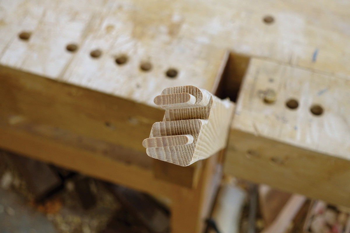
Remove the outside shoulder material with a crosscut saw. Remove the weaving-slot material by freehand-drilling from the bottom of the slot halfway through from each side with a 5⁄16” bit. The piece should break out easily. Clean up the bottom of the slot with a narrow chisel. What remains in the middle next to the lower tenon can be cut out with a coping saw. Now remove the small amount of remaining waste on either end of each tenon down to the shoulder. Shape the edges of the tenons round with a rasp and test the fit to the frames.
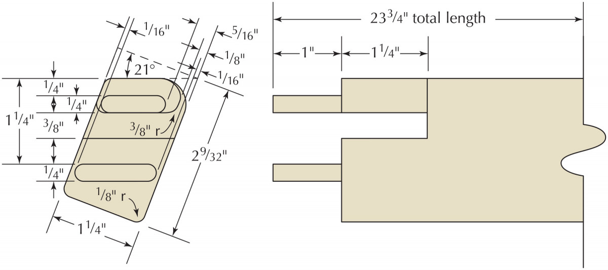
Rear seat rail profile
There is a small bit of material – 1⁄8” wide – that must be removed near the weaving slot. This will allow the paper cord to pass through without getting pinched when the chair is unfolded. See photo above, center.
Round over the acute corner of the bevel with a 3⁄8“-radius roundover bit. While you’re set up, round over the corners of the other rails according to the drawings. Now ease the edges of the slot with a rasp and blend them into the roundover.
With an 1⁄8“-radius roundover bit finish easing all the remaining edges on the crossrails as indicated in the drawings.
Twist & Shout
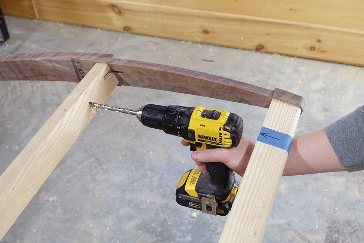
Follow the arrow. A bit of painter’s tape with an arrow to align your drill with is a big help
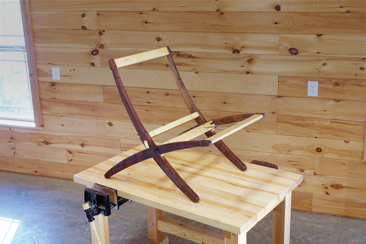
Here’s where the rubber meets the road. If you did a good job on the joinery, it will show here. Dry assemble both the frames and lay them on a flat surface, such as your table saw. There’s no simple solution to fixing a twist in a frame, but likely issues will be found in tenons and/or mortises that are not coplanar. Also, make sure your sides are parallel so they don’t rub when the frames are opened and closed.
Once you’re happy with the fit of the frames, it’s time install the two stainless steel weaving bars on the seat frame.
These bars run from the front rail to the back rail, one on both sides of the seat. On the back rail, measure 3327⁄32” from the inside of the frame and 3⁄4” up from the bottom edge, and mark a point to start your drill bit.
Support pin support. A thin spacer and a stick of wood will aid in drilling your support pins. The stick is the angle guide.
Do the same on the front rail, but measure 7⁄16” up from the bottom edge.
Now drill a 3⁄8“-diameter x 7⁄8“-deep hole, keeping the drill in line with the hole location on the opposite rail.
Sand all the parts now, but be careful to not remove material from the areas where the cross rails meet the side frame. Completely dry-assemble the chair with the weave bars and hinge hardware, then check to ensure everything moves freely. Make sure to include the washers between the hinge leaf and the backrest frame.
When you’re happy with the results, glue each frame assembly separately and set them aside on a flat surface to dry – and don’t forget the weaving bars.
A Little Support, Please
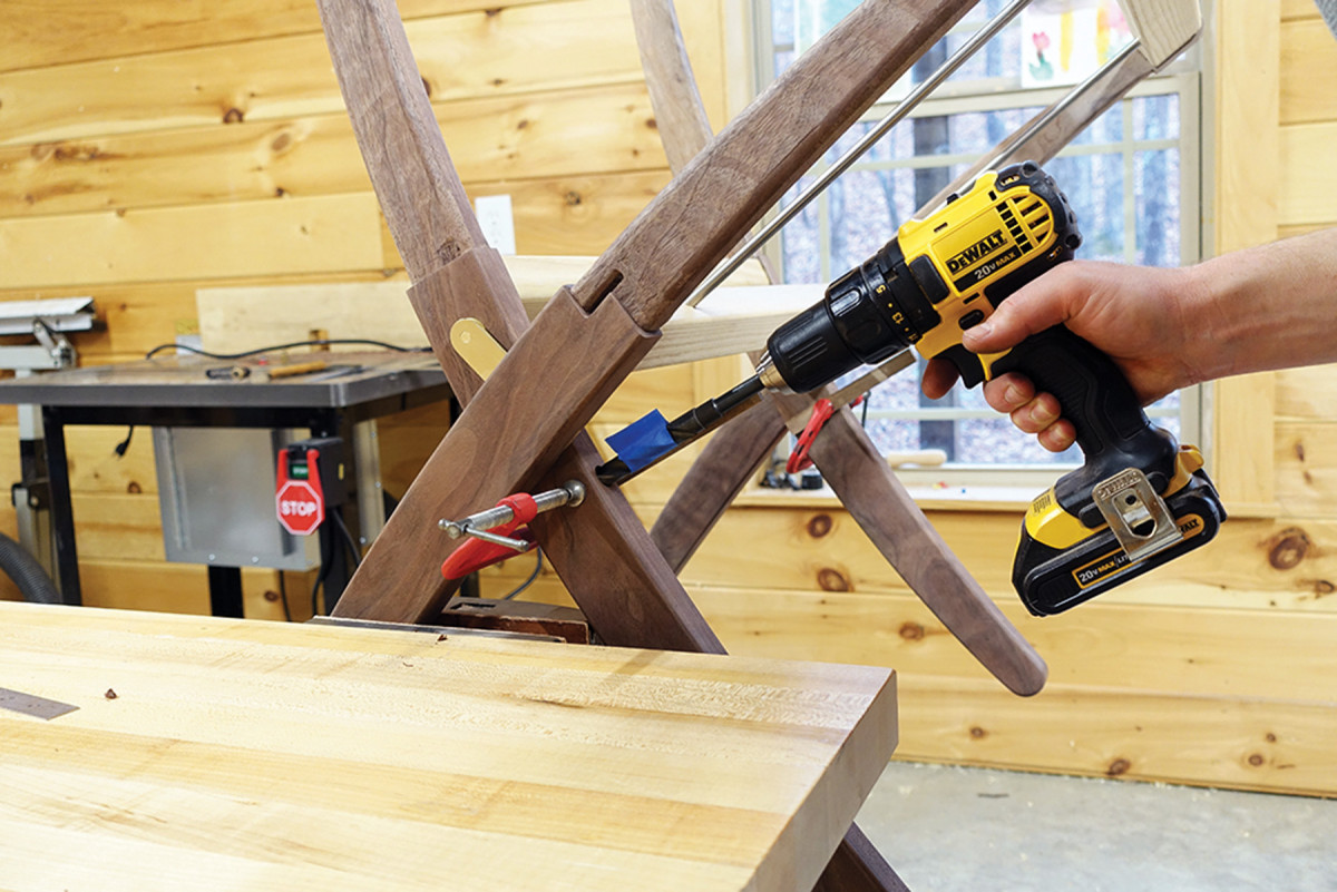
Angle guide. Open the frame and drill using the angle guide for orientation.
To reduce the stress on the hinge, install the two support pins you made earlier. These go in the backrest legs and make contact with the rear seat rail’s bottom edge when the chair is opened. Thus, the seat’s downward force is partially supported on these pins.
To find the pin locations, assemble the chair completely, including the hinge hardware, and unfold the assembly.
Insert a 1⁄32“-thick wooden spacer between the back rail and the leg of the backrest frame on both sides. Locate the pin hole’s center point by simply resting a 1⁄2” bit against the bottom edge of the seat rail and marking the center of the backrest leg.
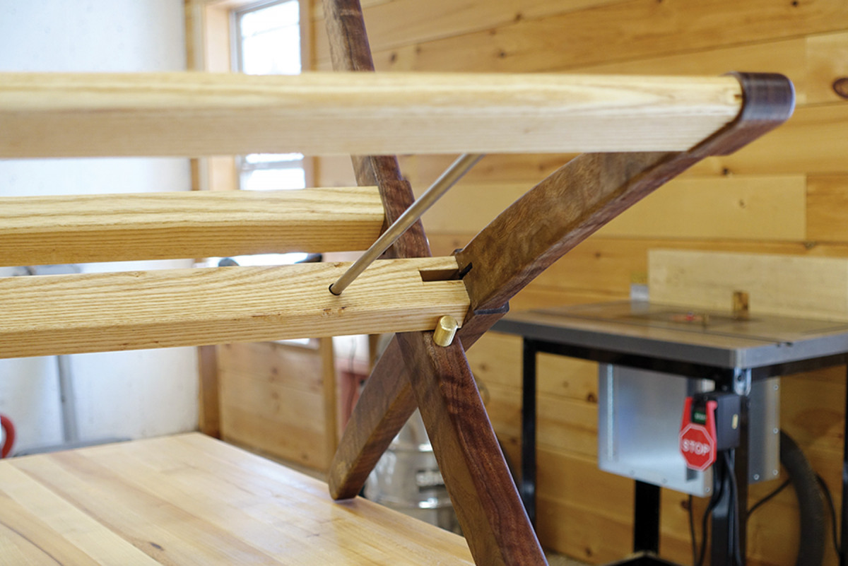
Interior view. Here’s what the frame looks like from the inside, with the weave bar and seat support pin installed.
If your drill bit is long enough, you can simply free-hand drill this hole by aligning the drill shaft with the rail’s bottom edge. If not, you’ll need to make a drilling angle guide out of a piece of wood approximately 3⁄4” x 1⁄4” x 6″. Align this with the bottom edge of the seat rail and clamp it against the leg of the backrest. Partially open the frame and drill this hole 1″ deep while using your angle guide to keep the correct orientation. Glue the pins in place, close the frame and let them dry.
Separate the seat and backrest then finish as desired. I’ve taken a liking to Osmo hard-wax oil floor finishes. For light-colored hardwoods such as white oak or beech, a traditional Danish soap finish is lovely.
Here are some supplies and tools we find essential in our everyday work around the shop. We may receive a commission from sales referred by our links; however, we have carefully selected these products for their usefulness and quality.