


We may receive a commission when you use our affiliate links. However, this does not impact our recommendations.
Full-sized downloads and cut list at bottom of article.
Project #1923 • Skill Level: Advanced • Time: 1 Week • Cost: $250
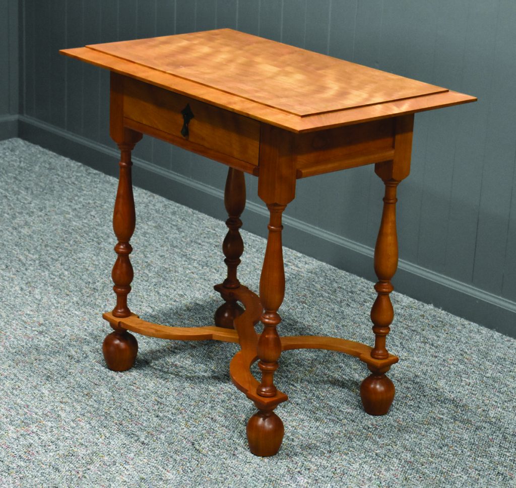
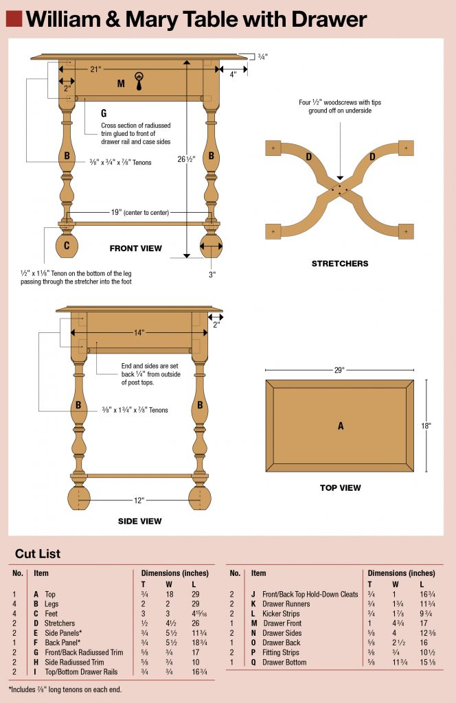
I’m not a fan of period furniture from England. The English emphasis on the horizontal conflicts with the American emphasis on the aspiring vertical that I find so appealing in period furniture built in this country. But, of course, there are exceptions, like this petite William-and-Mary one-drawer table which I found represented by a tiny black-and-white photo in a 30-year-old issue of The Magazine Antiques. Like nearly all William-and-Mary tables from both sides of the Atlantic, this example is distinguished by well-conceived turnings, oversized onion feet, a wide lip around the top, and a variation of the William-and-Mary X-stretcher.
Prepping
After I had generated scaled front and side drawings, I used this information to create the necessary pair of story sticks and the stretcher pattern. The stretcher pattern was a bit of a puzzle until I figured out the geometry the original maker had used. In the case of this table, that geometry is based on two compass-drawn circles centered on a point half between the two stretcher blocks on one end of the table on a line connecting the inside edges of two of those two blocks. (NOTE: The stretcher blocks are the four squares on the ends of the stretcher arms through which the table’s four legs penetrate. ) One of the circles represents the inside edge of a stretcher arc; the other, the outside edge. The two story sticks allowed me to quickly and easily establish locations long the turned feet and legs.
We won’t focus on the turning for these legs. Instead I’ll direct you to the August 2018 issue of this magazine for a more thorough approach to turning these legs. Instead, we’ll focus on the rest of the details in the pages to follow.
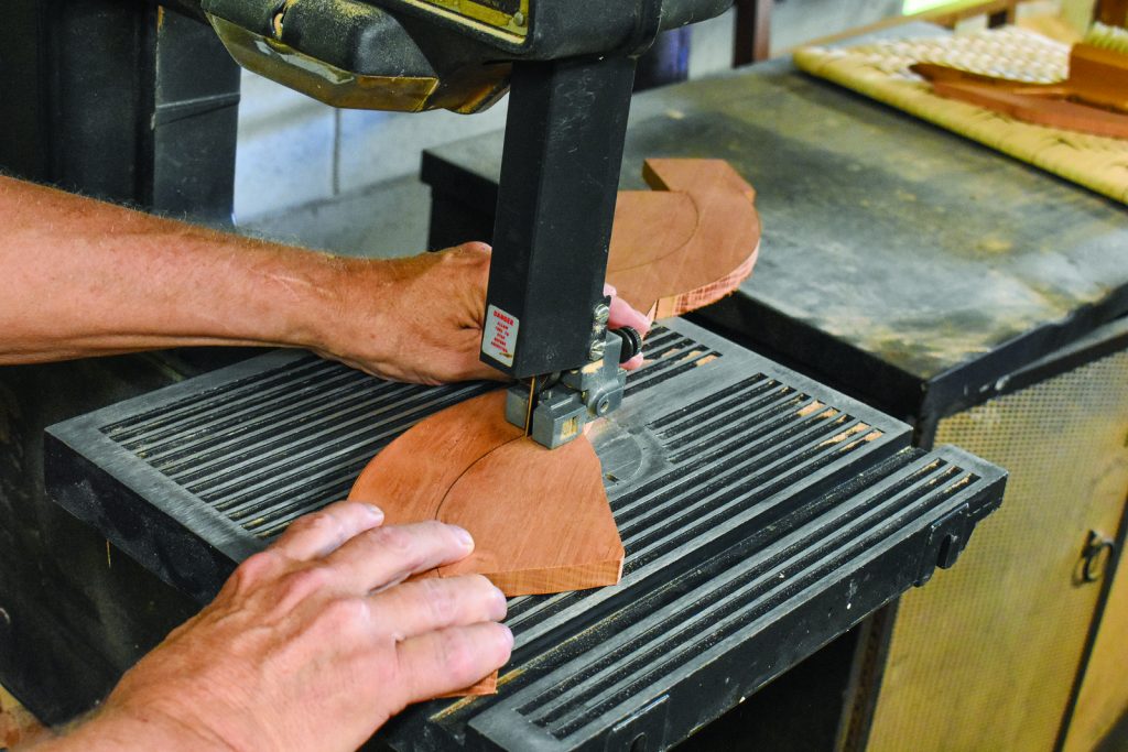
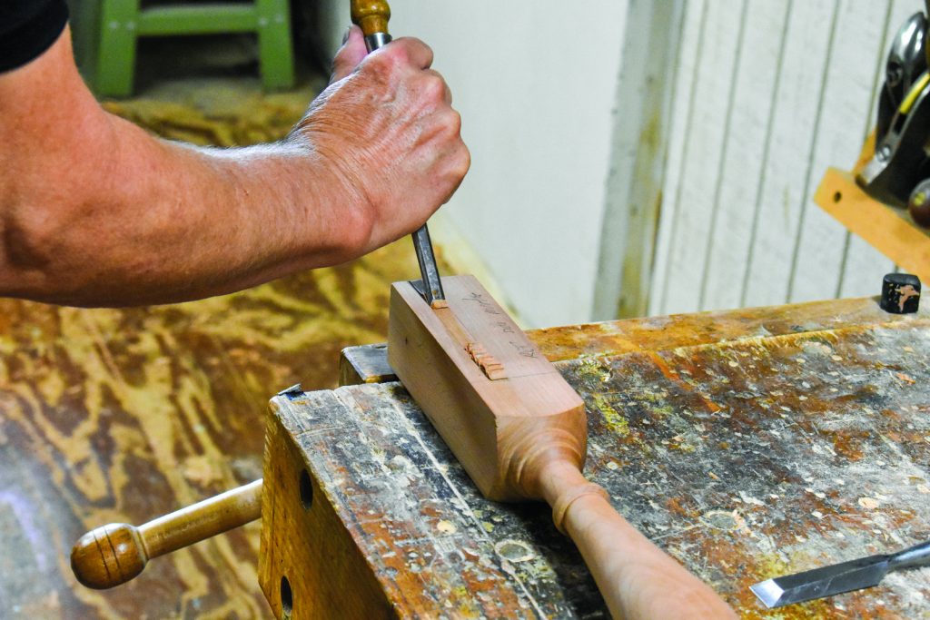
Fabricating the 69° Stretcher
When I described, to my friend (Rick Davis), the half-lap stretcher problem posed by this table, he volunteered to tackle the problem. My first thought was to measure the angle where the stretcher components crossed, then transfer that measurements to the tablesaw’s miter gauge in much the same way I used to create the half-lap joint in the X-stretcher of a William-and-Mary table I made for the April 2017 issue of this magazine. But the 69° I read from my plastic $3.00 protractor turned out to be not quite accurate enough to give us the proper distance between the centers of the four leg tenons.
So Rick gave the problem some thought and came up with an ingenious method of accurately marking those angles which led to a method for cutting the half-lap joints (his words below).
The X stretcher assembly must be cut with precision. The tenons at the bottom of the legs must align with holes at the ends the stretchers. Cutting the lap joint presents a problem, but by using a simple jig, the necessary precision can easily be achieved.
Draw the stretcher layout on a piece of 211/4″ by 141/4″ poster board, marking a 21/4″ square at each corner for the ends of the stretchers. Locate and mark the center of those 4 squares, and then finish drawing the stretchers per the plans.
Place the completed drawing on top of a piece of 3/4″ plywood or MDF, and with an awl press through the center point of the four 21/4″ squares to mark their location on the plywood. With a 1/2″ forstner bit, drill a hole at those 4 locations and place a short dowel in each hole.
Cut out one of the stretchers drawn on the poster board to use it as a template to draw the two stretchers on the boards that will be the final stretchers, using an awl to mark the center points for the holes. Cut out the stretchers on a band saw, drill the holes, and create the rounded edges on the squares with a block plane.
Place the stretchers onto the plywood jig to form their final X shape. With a sharp marking knife pressed tight against the top stretcher, mark a line onto the bottom stretcher to set the location for the first half of the lap joint. Use a palm router to cut out the waste on the bottom stretcher. In order to assure that there will be no blow out at the exit of the router cuts, you may also want to first use a dovetail saw to saw just off the line to the desired 1/4″ depth.
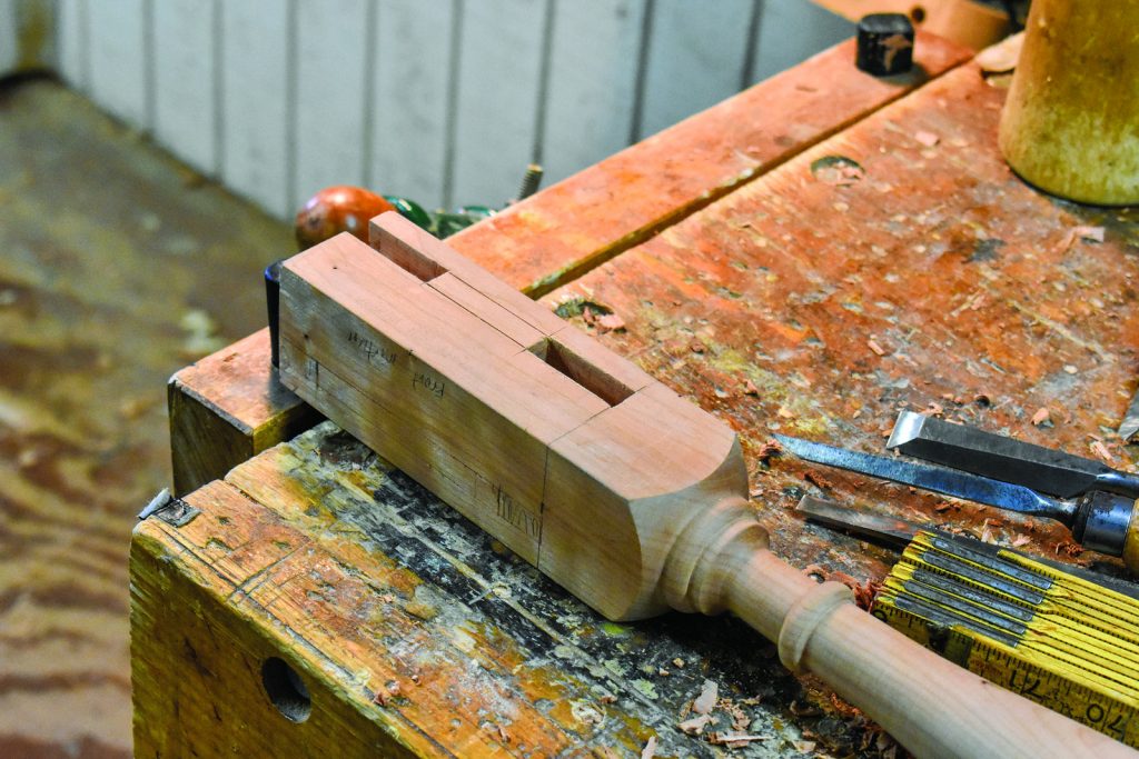
Put the two stretchers back onto the jig. They should make a perfect fit. Remove the two stretchers as a unit, flip it upside down, and place it back onto the jig. Again, using the upper stretcher as a guide, mark onto the second stretcher the location for the cuts, and rout out the waste on the second board. Return the two boards onto the jig for the final fit. Glue the top stretcher onto the bottom one and secure it in place with three #6 3/8″ screws. Let the assembly dry on the jig.
Measurements
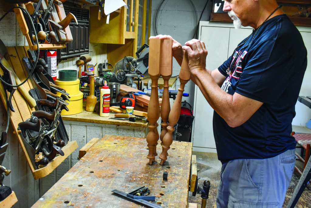
Accurate measurements are critical to the fabrication of any piece of hand-made furniture; nevertheless, it’s a mistake to assume that corresponding parts on any piece will have exactly the same measurements. In the case of the turned elements on these table legs, I produced lengths and diameters of reasonable accuracy, but a few minutes with a ruler and a pair of calipers would reveal discrepancies; however, this isn’t a problem because the human eye can’t read small errors across the surface of a piece of furniture . Plus—and even more important—these small discrepancies offer proof that this table was built by human hands.
What I mean is this: When you’re turning the legs or the feet of this table, and you realize that the vase on one legs is a 1/16″ greater than the same vase on another leg, don’t panic. That isn’t a problem; that’s a virtue.
Carve Your Legs on a Lathe
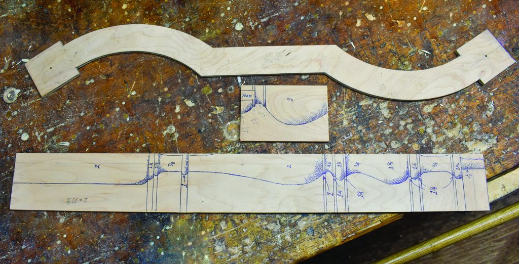 This particular table required the use of two story sticks—one for the feet and a second for the legs—as well as one pattern for the components of the X-stretcher.
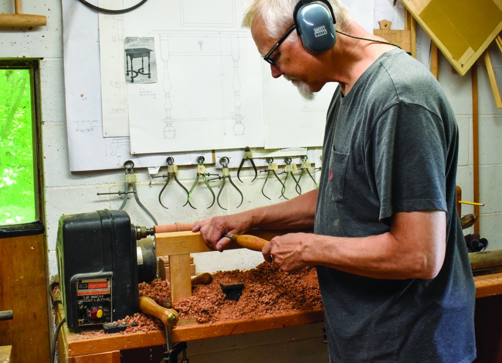
On the wall above my lathe, you can see the black-and-white photo on which I based my table. On the English original, the radiussed trim appears only below the drawer. On my version, that trim runs all around the piece. Also, I increased the overhang at each end of the table top. Please note the array of calipers. Each is set and labeled with a different diameter. Together, this array reflects every significant diameter on the leg.
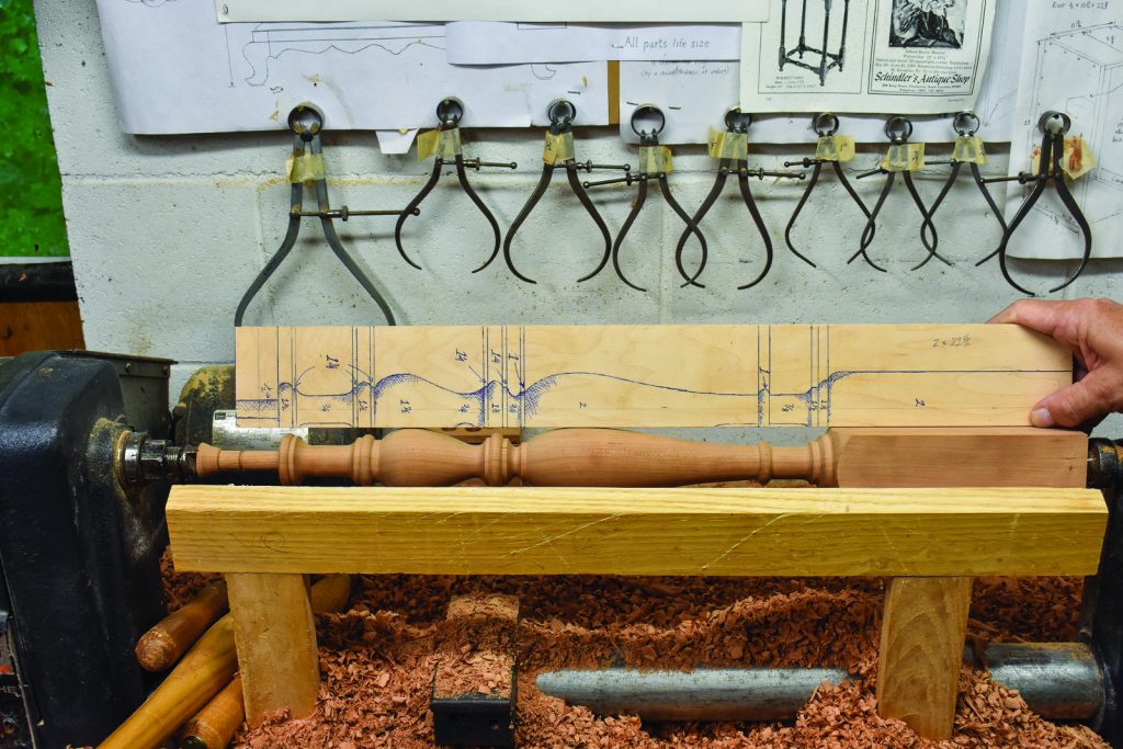 Notice the relationship between demarcations on the story stick and the various turned elements of the leg. Without this story stick, it would be necessary to measure the length of each segment by hand, a pretty cumbersome process that could lead to errors.
Cut Flawless Stretchers
A furniture-making friend Rick Davis volunteered to make the stretcher. He began by bandsawing the two halves from 1/2″ stock.
 He then drilled a 1/2″ mortise in the exact center of the squares at each end of each stretcher half.
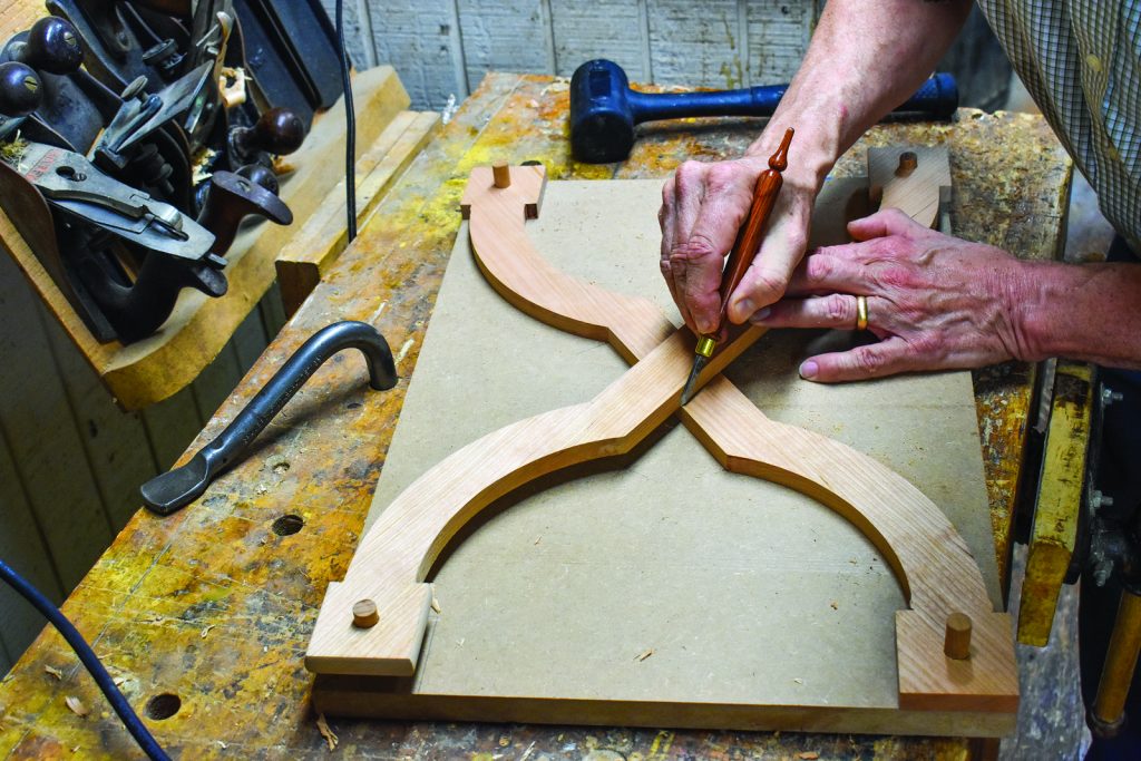 Rick then created this clever fixture to facilitate the accurate layout of the half-lap joint which connects the two stretcher halves. The 1/2″ dowels are press-fit into 1/2″ mortises drilled 12″ apart, front-to-back and 19″ apart, side-to-side (measurements are given center to center). When the stretcher components are placed over these stub dowels as shown here, they are in the exact alignment they will have in the finished table. This allowed Rick to accurately establish the angles and limits of the half-lap joints which you see him marking here.
Then with a fence set up an appropriate distance from the lap joint on the bottom stretcher component, he used a router to establish both the limits and angles of the lap joint.
Mortise & Tenons for the Table Base
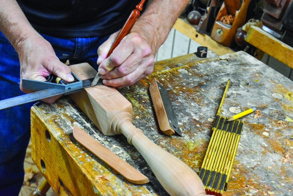
 When you’re laying out mortises on a set of table legs, it’s very easy to mark a mortise on the wrong face of one or more of the legs. To avoid that problem, after I’ve pencil-marked the mortises but before I knife-mark them, I bring the pencil-marked legs together in the alignment they will have in the finished table, and check to see that everything is the way it should be.
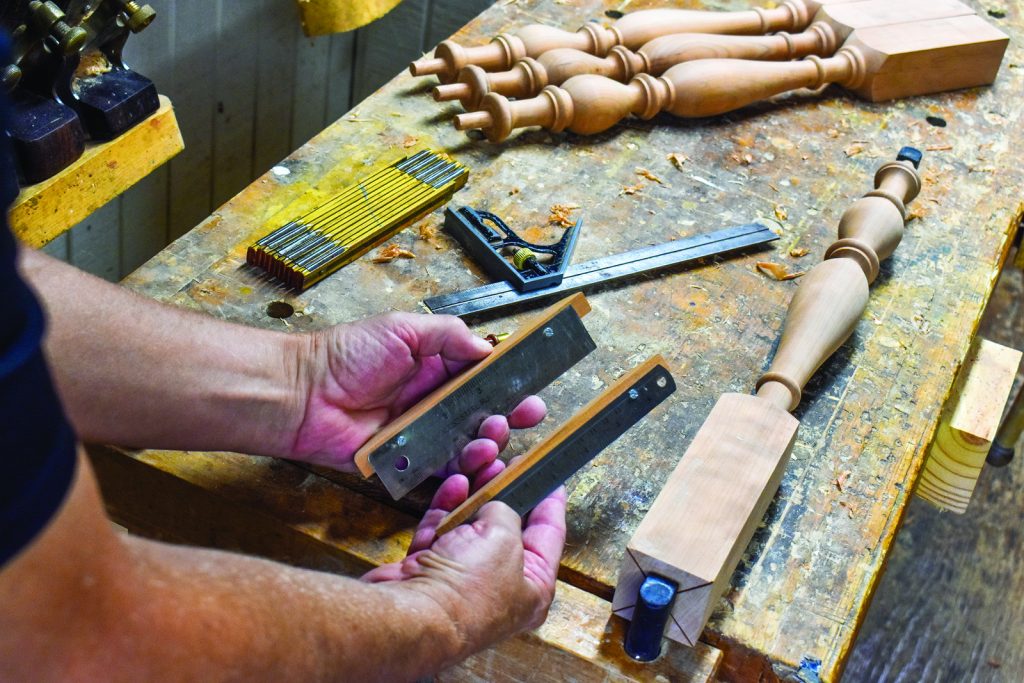 After struggling for many years to hold a metal rule in exactly the right position for knife-marking mortises, something kicked my brain into gear. I purchased a supply of 6″ metal rulers and attached wood fences to them that represented the inside and outside edges of each mortise. This makes mortise layout nearly idiot proof. You simply press the fence against the work and move your marking knife along the edge of the ruler.
 Mark the outside edge of the apron mortises. Notice the wider fenced ruler on the bench beside me. That will be used to mark the inside edges of those mortises.
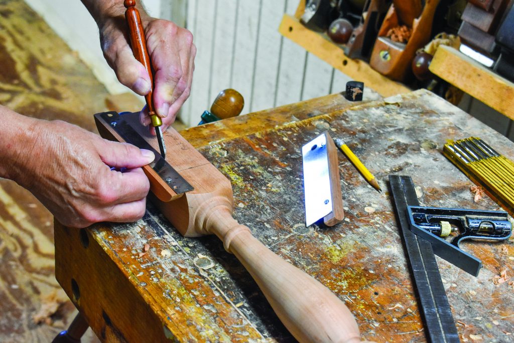
 I completed the knife marking using a tri-square to align the knife for cross-grain marks.
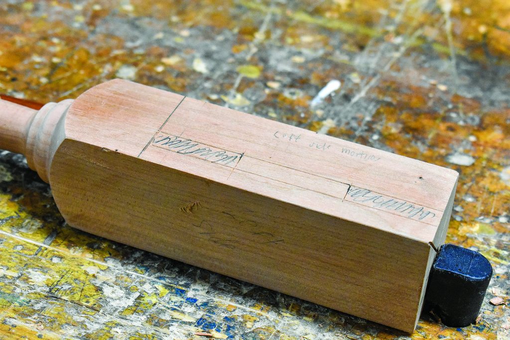 Here you can see how clean and accurate the knife marks are.
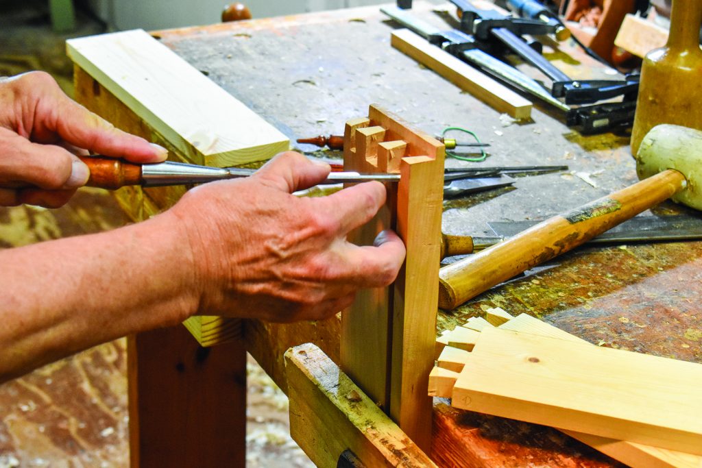
 For forty years, I’ve thought about buying a hollow-chisel mortiser, but somehow I always end up chopping my mortises by hand—which I believe is a pleasant way to pass a few hours in the shop. I find a comfortable working position, turn on the radio, put my hands on full auto, and before long I have a set of mortises.
 The finished hand-chopped mortises are pleasant to contemplate. I’m not sure I’d feel the same about mortises ground out by a machine. Plus who can hear a radio when the hollow-chisel mortise is chugging and clattering along.
 Perhaps oddly given the fact that I create mortises with chisels, I take the easy way out when cutting the tenons by thicknessing them on a stack of dado cutters. I then finish by bandsawing away the sections that are not part of the tenons.
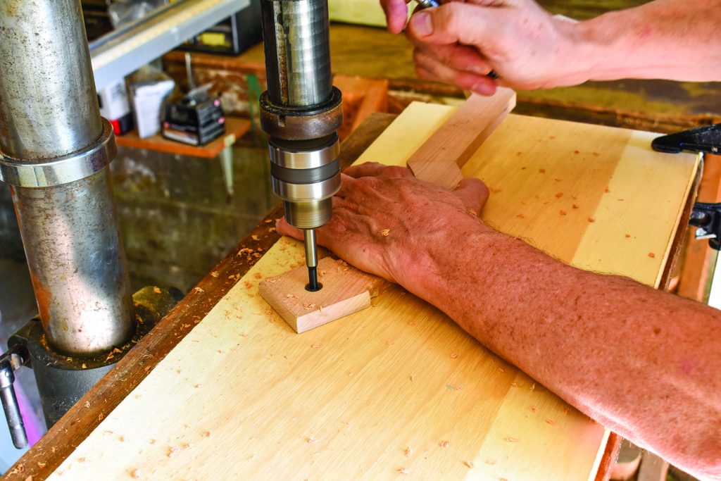
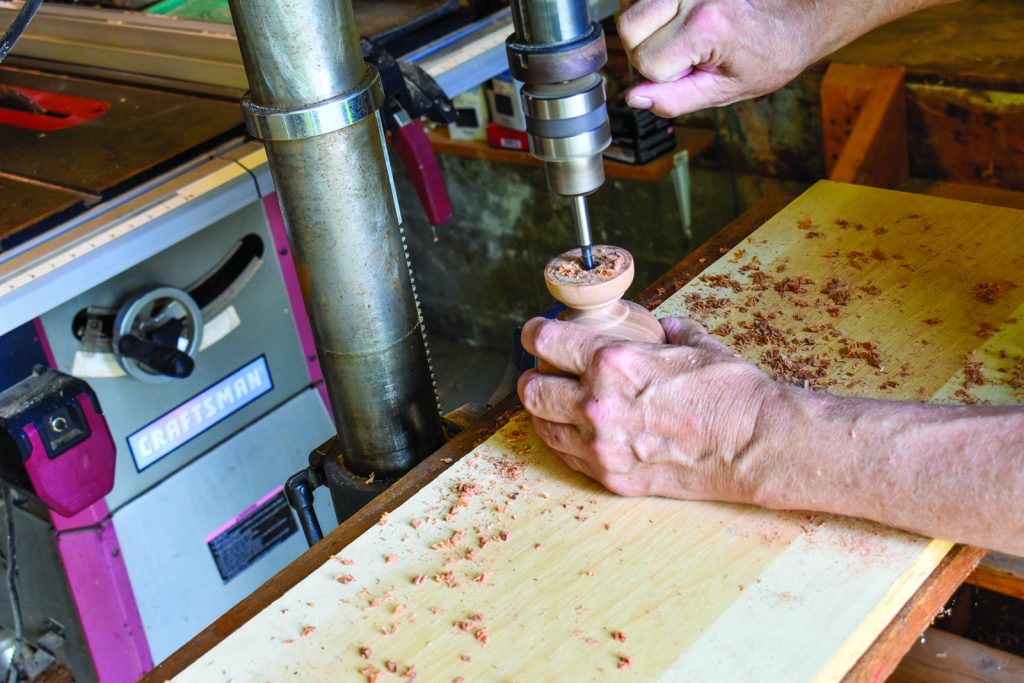 I cut the mortise into the top of each foot by holding the foot in my hand while I bring a 1/2″ Forstner bit into the end grain. This would be difficult or impossible with a twist bit which imparts a powerful rotation.
Finishing the Table Top
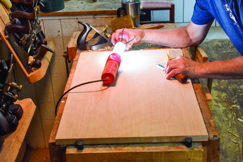 Almost fifty years ago when I began making stuff from wood, I bought a belt sander and a vibrating sander, and those two tools destroyed every surface they touched. No matter how light my touch, the edges of the belt sander’s belt cut grooves in the surfaces, and the vibrating sander left small circular scratches. So I pitched these tools, and ever since, I’ve finished surfaces as you see here. Working in the illumination of strong side light, I first cleaned up the surface with a really good finishing plane set to take a shaving far thinner than a facial tissue, then went back in with a very sharp chisel used as a scraper to clean up tiny areas of tearout. I finished the surfaces through hours of work with a hand-sanding block and a variety of sanding grits. Noble efforts maybe but more drudgery than I really want to invest in getting a clean surface.
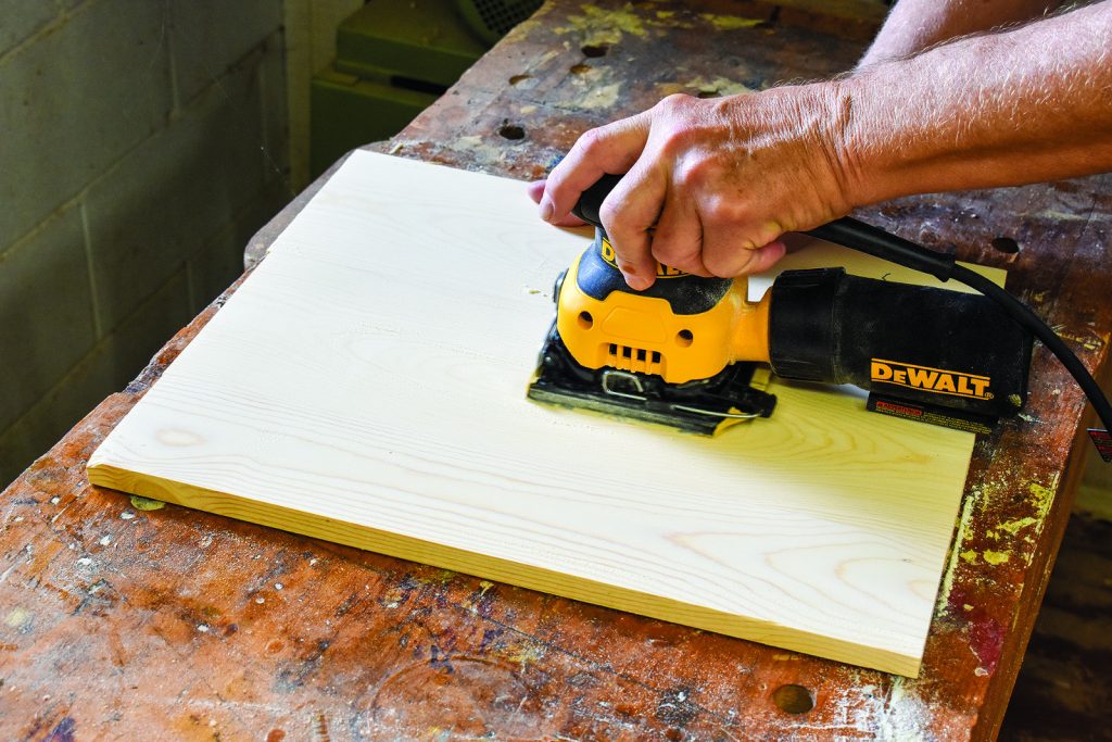 Then one day during my work on this table, I walked through the local Lowe’s store and saw this sander. I decided to give it a chance, and it was a revelation. In 20 minutes, I could produce a clean, flat, scratch and groove-free surface. Progress.
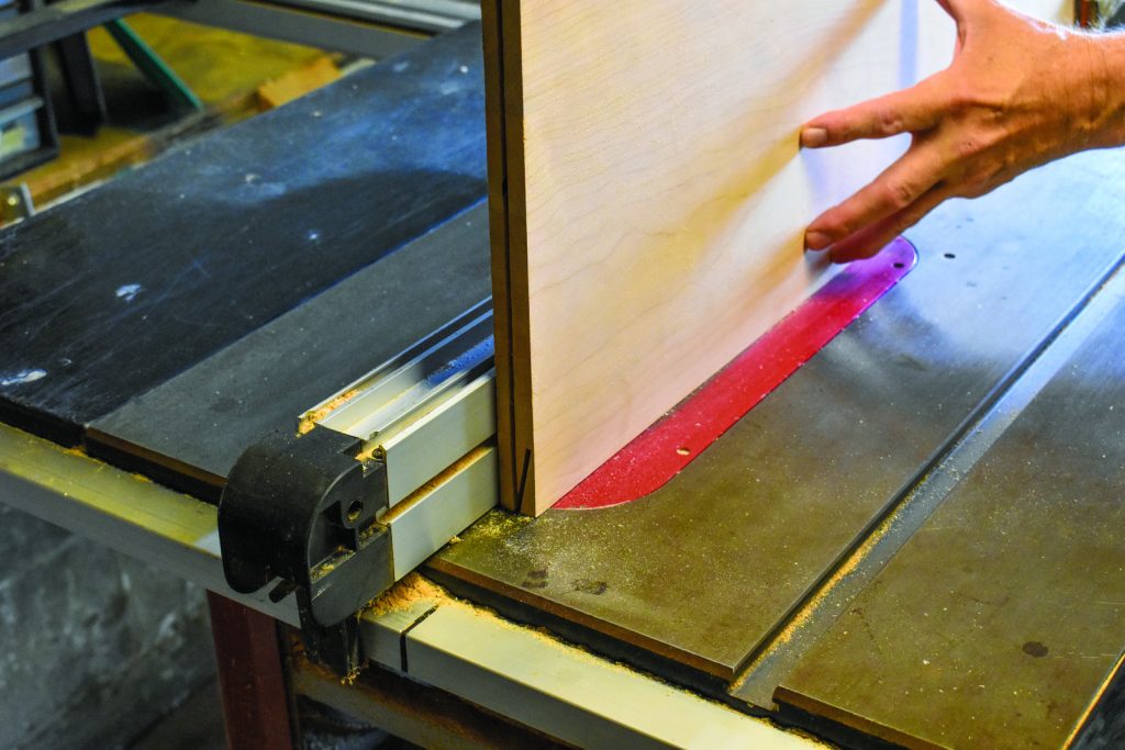 The wide lip around the top could be roughed in using hand planes, but the tablesaw makes such quick work of this task: once around with the top stood on its edge as shown here, then once around again with the top laid flat on the saw table.
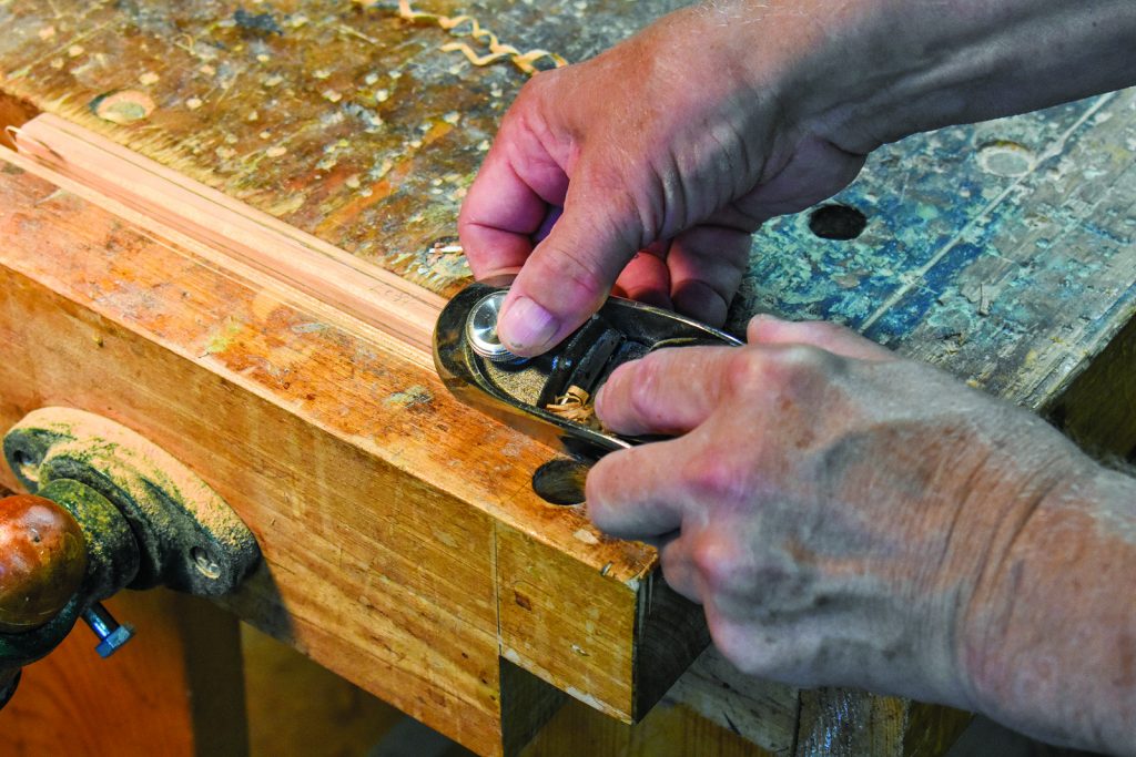
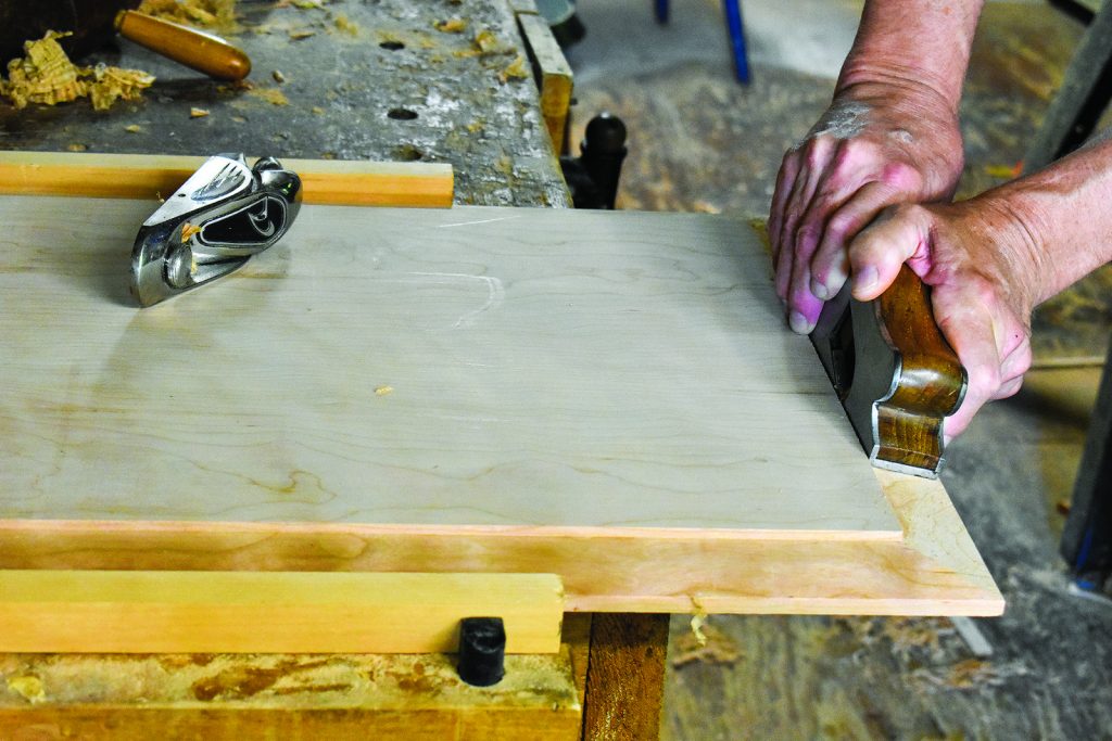 But good hand planes are essential to fine tune the lip. I used this wide shoulder plane up close to the filet (and on the filet itself with the shoulder plane on its side) and the little block plane on the left for the rest of the lip.
Glue Up & Assembly
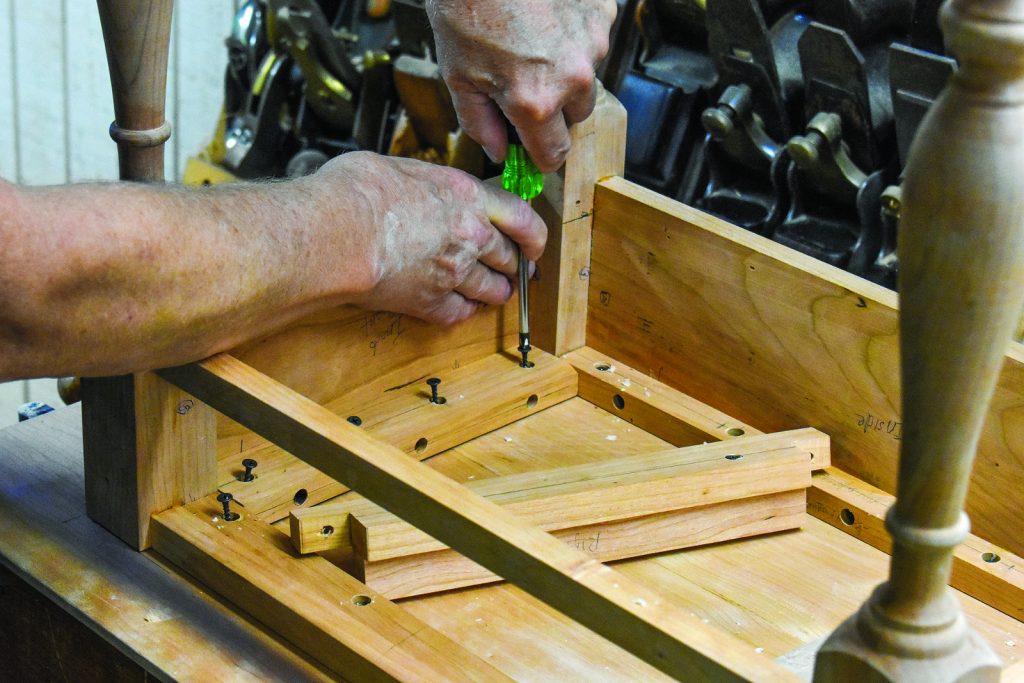
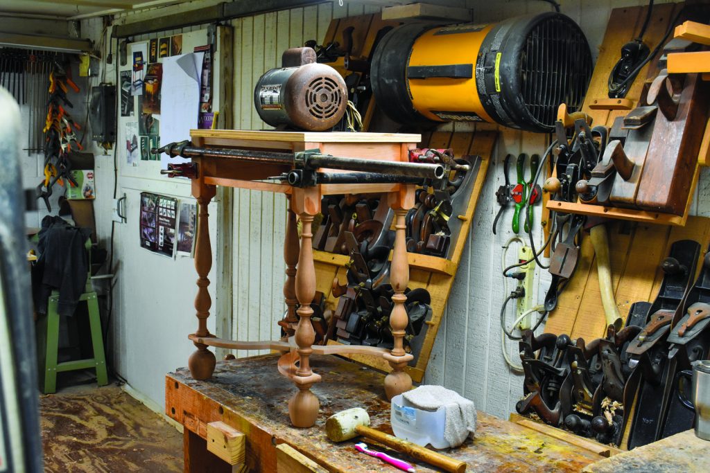 Sometimes when I’m gluing up a table base, I’ll glue the end panels first, then join them with the front and back members. This table, however, was small enough that I could do the whole base at once. The heavy motor on top ensures that the bottoms of all four feet are in the same plane.
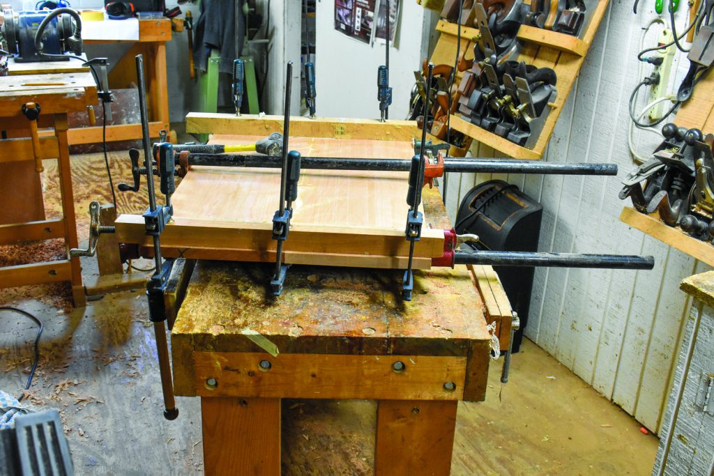 I used nine clamps to create the two-board table top: three pipe clamps across, staggered bottom and top and three vertical bar clamps on each end pressing a straight-edged caul tight against the surface. This multitude of clamps ensures both a tight glue joint and a flat surface
 The top is held in place primarily by a pair of 3/4″ x 1 cleats, one in front, the other at the rear, but the screws in the kicker strips add additional hold-down strength for the top. The trick to using screws to hold a top down is to make sure that the hole through the cleat is slightly larger than the diameter of the screw. That way the top can expand and contract across its width without cracking.
Radiussed Trim
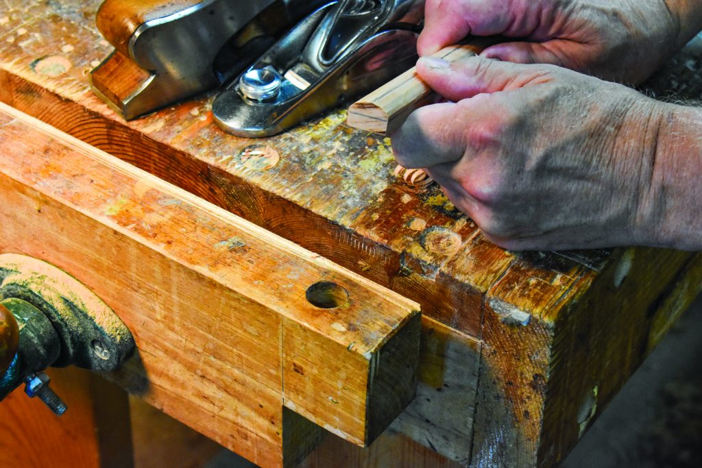
 I began the creation of the radiussed trim at the bottom of the apron by milling some 5/8 x 3/4 stock. I then cut the material to length and marked the flush point on either end. After establishing some guidelines, I roughed in the trim radius using a block plane.
 Here you can see the flush line of the end grain, as well as the guidelines and the rough plane work. Each trim piece is then finished with a rasp and sandpaper.
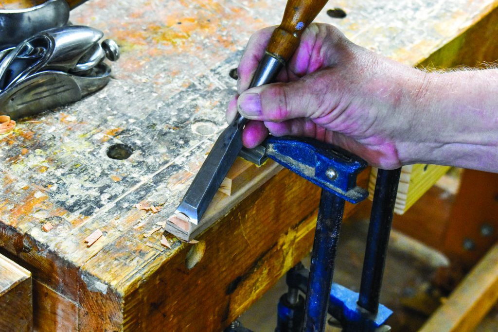 The taper on each end of each trim piece was cut with a chisel.
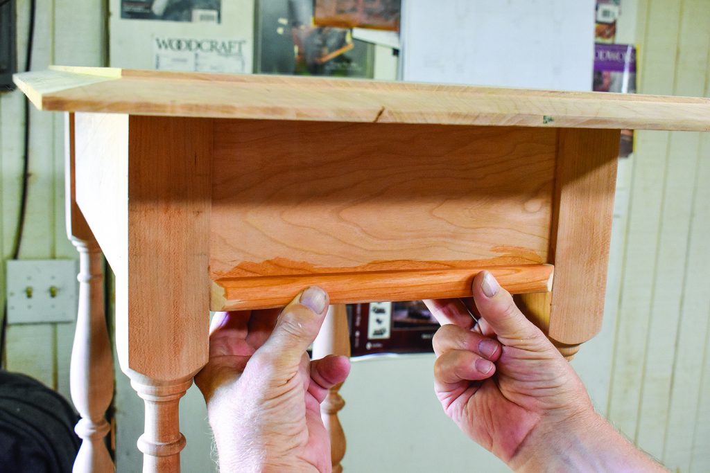 The glued trim pieces were then installed by holding them in place for a slow 60 count, giving the glue time to grab. (This can’t be done if the back of the trim piece is bowed or twisted.)
Lastly, the Drawer
 I cut the half-blind drawer dovetails by hand.
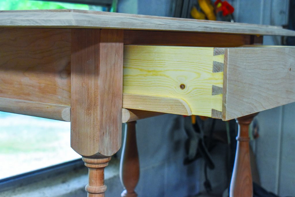 Notice the fitting strip on the side of this drawer. These strips make it much easier to fit a drawer to its opening because you need to plane only the strip—not the entire drawer side. (I think these strips are my invention, but it could be that I stole the idea from someone else years ago.)
Full-Sized Front View Download
Full-Sized Drawer Illustration Download
Here are some supplies and tools we find essential in our everyday work around the shop. We may receive a commission from sales referred by our links; however, we have carefully selected these products for their usefulness and quality.


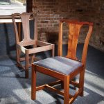

While I am not a fan of the Wm and Mary style, this caught my interest and just might be a future project.
Thanks