


We may receive a commission when you use our affiliate links. However, this does not impact our recommendations.

Build a standing desk tailored to your body.
I designed this compact stand-up desk to meet a prescription from my doctor to be less sedentary. “Sitting is the new smoking,” I was admonished.
It was also to give me a challenge: to create a project start to finish almost entirely within the realm of pre-industrial technology, ramping up my education in how traditional artisans got things done.
My goals were to design the desk to human body-related harmonic ratios (a design sensibility predominant through the end of the 18th century), use joinery that negated the need for glue or fasteners for structural longevity and build the project primarily with hand-powered tools.
The desk also had to be perfectly comfortable to work at and to be, at the least, handsome.
The Design Process
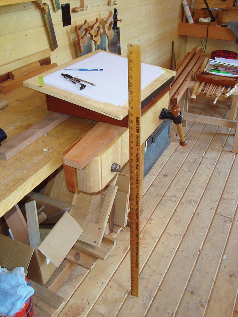
Just right. The distance from the elbow to the ground (about five hand spans) is a comfortable height for most people (above). I set a mock writing surface at the best height and slope for me (left), then used that measurement to mark a story stick. All the desk dimensions are based on a “module” of one hand span, or one-fifth the distance I determined.
 The design process began with determining a single parameter: the height of the drawing surface at its front edge.
For me (and for most people) this works out to be about elbow height – which I marked on a stick resting against a cobbled-together mock-up of the desk’s top surface (see photo above). I also used the mock-up to determine a comfortable slope (mine was 1:5).
I continued to develop all the other dimensions as harmonic whole-number ratios to the floor-to-elbow height.
That comfortable working height worked out to be five hand spans from the floor – typical for adults.
I then used one of these hand spans as the common factor (or “module,” as it would be called traditionally) to develop the proportions of the other dimensions.
■ For ample room for drawing, the width needs to be at least a shoulder width (which is two hand spans) plus a hand span. The width-to-height ratio therefore resolves to a 3:5 rectangle.
■ The depth of the desk should be at least a forearm from the elbow joint to the middle fingertip (which is two hand spans). So the depth-to-height ratio resolves to a 2:5 rectangle.
The width of the legs is added to the outside of the 3:5 ratio rectangle of the face and the 2:5 ratio rectangle of the side elevation. This adds more breadth to the design and therefore more stability.
■ The top of the desk resolves to a 2:3 ratio rectangle. Note that this ratio also accommodates the size and shape of most drawing papers.
While I included a cutlist for this project, the dimensions listed are from the desk I made using my hand span and elbow height as the starting point. Your desk’s final dimensions can vary according to your own proportions.
Telling the Story (Stick)
Using the tool set of my eye, a set of dividers and a straightedge, I continued to develop proportionally scaled elevation drawings using these ratios, which I then erected in an isometric view. Having a true-scale drawing allowed me to get a good picture of what the piece would look like in three dimensions.
When I liked what I saw in the elevations and the isometric, I transferred the proportioned elements to a story stick using dividers. The layout revolves around the primary index marks transferred from the base/floor line and the elbow-height mark recorded on the stick from the mock-up.
I drew the module (one-fifth the distance from my elbow to the ground) and divided that in half, then into fifths. These lengths are all the dimensions I needed to lay out most of the elements of the design. I made full-size templates of the side of the box and of the curved corner bracket.
Joinery Elements
Strong, durable joinery in a tall and relatively slender structure such as this is critical. I chose drawbored mortise-and-tenon joints for the apron-to-leg connections, wedged through-tenons for the base’s side rails and tusked through-tenons for the cross stretcher-to-rail connection.
Each of these joints is adjustable over time (in fact, the entire base can be knocked down for repair or transport if necessary), and the joints provide opposing (locking) connective forces. The desk box is dovetailed at its corners and features a tongue-and-groove bottom and a writing surface capped with pegged breadboard ends.
None of these joints relies on glue or fasteners to resist bearing forces. The box is secured to the base by removable screws, while the box-to-base transition is hidden behind a piece of moulding permanently attached to the base.
Because this project is essentially joining two independent structures – a base frame and a dovetailed box with a sloped lid – it’s best to approach the construction sequence in two sections: the base first, then the box. Note that this construction sequence assumes the builder will be doing primarily hand-tool joinery, fitting and smoothing.
Standing Desk Cut List
No.ItemDimensions (inches)MaterialComments
t w l
❏ 4 Legs 1 5⁄8 x 1 5⁄8 x 35 7⁄8 Mahogany
❏ 2 Apron sides 3⁄4 x 4 x 18 Mahogany 1″ TBE*
❏ 2 Apron front/back 3⁄4 x 4 x 26 Mahogany 1″ TBE*
❏ 2 Side stretchers 3⁄4 x 2 3⁄8 x 19 5⁄8 Mahogany 113⁄16” TBE*
❏ 1 Cross stretcher 3⁄4 x 1 5⁄8 x 27 1⁄4 Mahogany 23⁄8” TBE*
❏ 8 Brackets 3⁄4 x 3 3⁄16 x 4 Mahogany 3⁄8” stub tenon
❏ 4 Corner blocks 3⁄4 x 3 x 3 Mahogany Shape as a triangle box
❏ 2 Sides 3⁄4 x 7 3⁄16 x 17 5⁄8 Mahogany
❏ 1 Front 3⁄4 x 4 x 25 5⁄8 Mahogany
❏ 1 Back 3⁄4 x 7 3⁄16 x 25 5⁄8 Mahogany
❏ 1 Top 3⁄4 x 16 x 23 3⁄4 Mahogany 3⁄8” TBE**
❏ 2 Breadboard ends 3⁄4 x 3 x 16 Mahogany
❏ 1 Fixed top 3⁄4 x 4 x 27 1⁄4 Mahogany
❏ 1 Fence 1⁄2 x 2 x 34 Mahogany
❏ 1 Ledger 5⁄8 x 1 1⁄2 x 27 1⁄4 Mahogany
❏ 1 Bottom 3⁄8 x 17 x 25 Mahogany †
❏ 1 Moulding 13⁄16 x 11⁄16 x 90 Mahogany
optional Additions
❏ 2 Shelves 3⁄4 x 11 x 12 Mahogany Radial-cut grain
❏ 2 Bottom shelf guides 3⁄4 x 3 x 24 Mahogany
❏ 2 Side shelf guides 3⁄4 x 1 1⁄2 x 24 Mahogany
❏ 1 Interior divider 1⁄2 x 1 1⁄8 x 24 5⁄8 Mahogany 3⁄8” stub TBE*
*TBE = Tenon both ends; **Tenon extends to 11⁄4” at peg locations; † = Size to fit groove
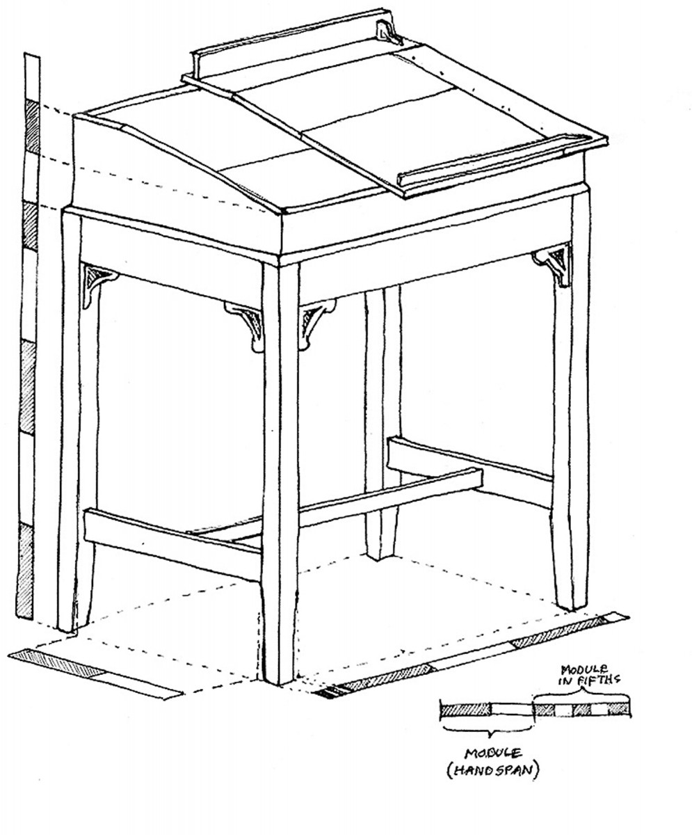
Isometric View. Isometrics. This is an isometric drawing, not a true perspective drawing. It looks a little weird, but it is much easier to draw because the module length doesn’t change along any dimension as it would in a true perspective view.
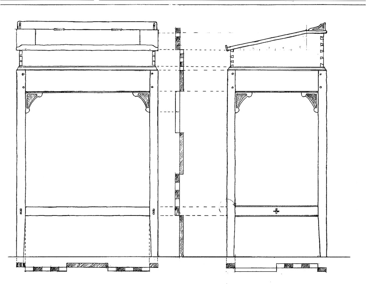
Elevation. Dividing it up. Front and side views show how multiples and divisions of the module define all the elements of the design.
Build the Base Frame
Working together. I clamped the legs together to chop mortises for the aprons and brackets, then used a router plane to clean the bottoms of the shallow mortises for the brackets.
Select straight-grained, straight-running stock for the legs, preferably out of material thick enough to allow cutting each leg so each face exhibits a straight grain pattern. This pattern contributes to stability and prevents wild grain patterns on the legs that can make them look bent or swollen
The width of the square tapered legs is one-fifteenth the distance between the bottom of the apron and the bottom of the stretcher. Each leg will taper in its bottom fifth by one-fifth its width.
After dimensioning the leg stock square, lay out their lengths from the story stick, starting from a squared end. To avoid discrepancies, clamp all four legs together and lay out the lengths simultaneously.
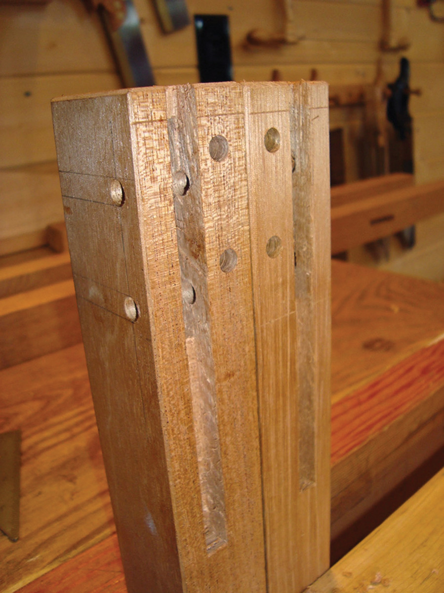
Ready to go. The top of each leg, like the two here, has mortises for aprons and brackets, and holes for the drawbore pegs.
Clearly mark the end cut, but make another mark to delineate an extra inch or so at the top (called the “horn”) to support the wood under mortising pressure. You’ll cut off this horn when the mortises are complete.
Look over the grain and orient the legs for best appearance, hiding the worst-looking faces at the rear of the desk. Mark the top and bottom ends with an orientation scheme – I use circles.
Lay out the location of the drawbore pegs and drill through from the front. Be sure to use backing blocks if you are power drilling, or come from both directions if using a brace and bit.
Mark from the story stick the location and lengths of the apron and stub tenons on the appropriate faces of the legs. You can clamp the four legs together for simultaneous marking to speed up the process.
Mark the width of the mortises with a marking gauge set to the width of the mortise chisel you’ll be using (in this case, a chisel a little bit wider than one-third the thickness of the apron stock).
Be sure to index the shoulder of the gauge to the outside face of the legs. Make marks indicating the stub and the apron-mortise area. Make crisp marks along their lengths to register the chisel for final paring.
Begin with the mortise for the haunched apron tenons. Mark the depth of the mortises on your chisel with tape or permanent marker. Note: There will be two marks, because one mortise is shallower than the other, though they will eventually join to become equal depth. To prevent blow-out, cut the shallow mortise first.
Chop out the mortises to the mark, checking your progress with a small try square blade set to the finished depth. (With practice, I think you’ll find that there is no efficiency advantage in drilling out the waste.) As you chop the waste away, you’ll discover that the mortises will eventually intersect inside the legs.
Chop out the stub-tenon’s mortise, working back from the apron mortise; test the depth with a combination square.
For the side stretchers, from the story stick lay out and mark the mortise location and length on each of the legs. Mark the outside face, then square around to the inside face.
Set the marking gauge to the appropriate width, then mark the width of the mortise on both front and back faces. Clearly mark the mortise area so you don’t chop outside the marks. Make knife lines at the extent of the lengths to register the chisel.
Chop out the mortise going halfway through from each face.
Taper the mortise slightly to the outside. I use a simple jig (a block with a 1:9 slope clamped to the workpiece) to hold the chisel. Be sure to back up the leg firmly against a piece of scrap to prevent blow-out as the chisel emerges.
Taper the Legs
I tapered the legs slightly on the inside faces starting just below the location of the stretcher (which is one-fifth the height of the front of the desk). The taper is one-fifth the thickness of the leg.
Lay out the cut lines on the inside faces from the story stick and remove the waste with a drawknife followed by a try plane.
Cut off the horn at the top of the leg to the finished cut line. Double-check to be sure all the legs are the same length.
Make the Aprons
Proportional taper. To taper the lower fifth of each leg, I used a drawknife to bevel down to a cut line on each side, then removed the waste. The black marks are from a grease pencil.
Size the apron stock to thickness and width and lay out the lengths from the story stick from a squared end. Clearly mark the shoulder cut line and the cut line indicating the end of the tenon. Square these lines all the way around with a knife. Saw each apron to length.
Clean up the end cuts with a block plane to see the layout lines and mark the tenon cheek cuts with the mortise gauge. Be sure to index the shoulder to the outside face of each apron. The tenon will be sized to the mortise (and therefore the mortise chisel) and will be centered on the board. Mark the haunch with a knife line. Also mark cut lines for the bracket’s stub mortise.
Choosing the best-looking pieces for the front and sides, make orientation marks on the top edge.
Score a “V” at the shoulder cut lines, then saw down to the tenon cheek marks on each face, including the haunch at the top and bottom.
If you are going to work a decorative bead along the outside bottom edge of the aprons, this is the time to do it.
Split prevention. Cutting the wedge slots at an angle helps prevent splitting by reducing the bending friction at the base.
Saw out the tenon cheeks to the shoulder and haunch cuts.
Miter the ends of the tenons, being careful to keep the angle oriented properly to the face of each apron. Next, chop out the stub mortise for the haunched tenon.
Now dry-fit the aprons one at a time into the legs, checking for square and for full closure against the shoulders. Tweak as necessary. Then assemble all four and check to see if the assembly is square by using a diagonal marking stick, pinch rods or equal corner-to-corner measurements. Adjust as necessary – usually by slightly changing the angle of the leg face meeting the apron shoulders with a plane. (More significant changes might require adjusting the tenon cheeks.)
Plow it out. I make drawbore pegs from a strip of walnut by plow-planing thin grooves until a 1⁄4″-square strip is released.
When it all looks good, mark the center points of the drawbore holes on the tenon cheeks using a drill bit with a center point, then withdraw the aprons.
Using an awl, move the mark in 1⁄16” toward the shoulder. When the peg is driven home, it will force the shoulders tight against the face of the legs.
Drill the drawbore holes in the tenons centered on the inset mark. Be sure to back up the tenon on a scrap of wood.
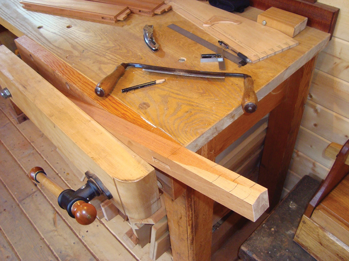
Make the Stretchers
Enter the octagon. I make the square strip into a octagon by planing the facets on a shop-made jig. Count the number of strokes on each facet, and mark the square faces to keep track of the worked facets.
Size the stretcher stock to thickness and width, then lay out the lengths from the story stick from a squared end of each stretcher.
Clearly mark the shoulder cut line and the line indicating the end of the tenon. Note that the side stretcher’s shoulders will be exactly the same distance apart as the those on the side aprons. Square these lines all the way around the stock with a knife.
Saw the two side stretchers and the cross stretcher to length and clean up the end cuts.
Use a mortise gauge to mark the cheek width of the tenons, then use a handsaw to cut the shoulder lines down to the cheek lines.
Cut the tenon cheeks down to the shoulder lines, then saw slots in the tenons to receive the wedges.
Again refer to the story stick to lay out the location of the cross stretcher’s through-mortise on each side stretcher. Mark your mortises, chop them out and work them to their final size.
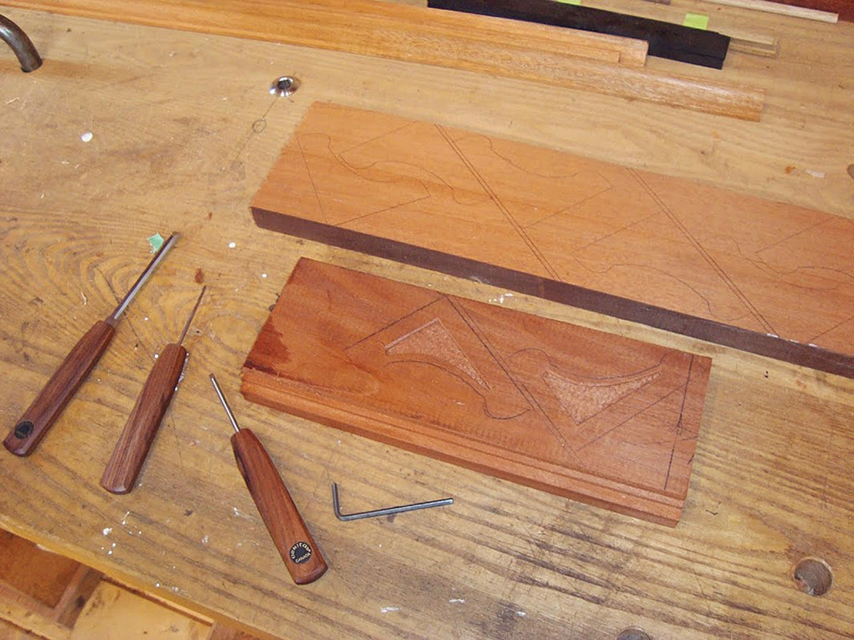
Casting a hex. I laid out the corner brackets at a diagonal to avoid cross grain at narrow sections. Using chisels and spokeshaves, I shaped the rounded edges. After I carved a depression, I tapped the wood with hex wrenches to add a decorative pattern.
Work a decorative bead detail (I added a 5⁄16” bead) on the top and bottom edge of the side stretchers.
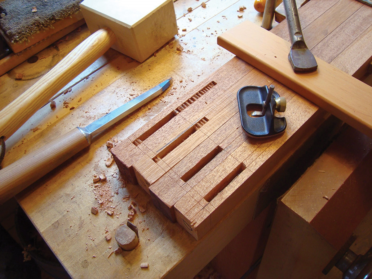
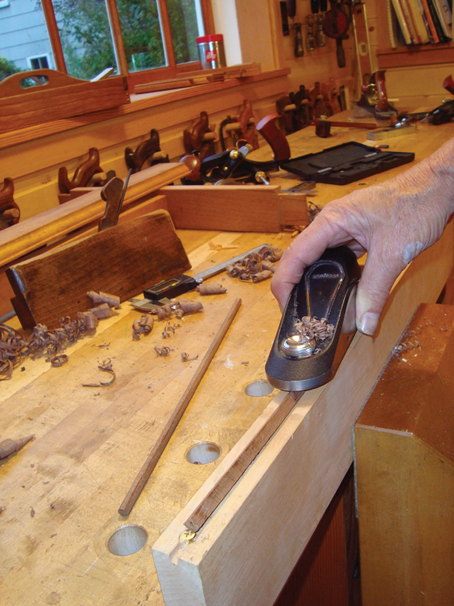
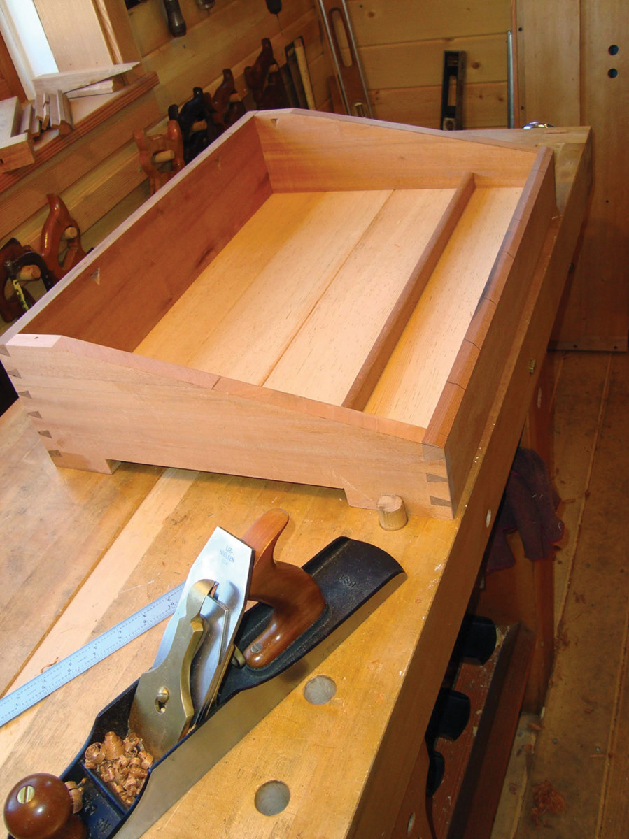
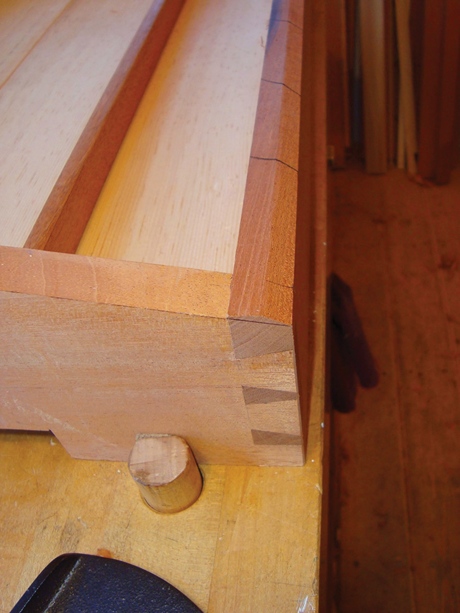
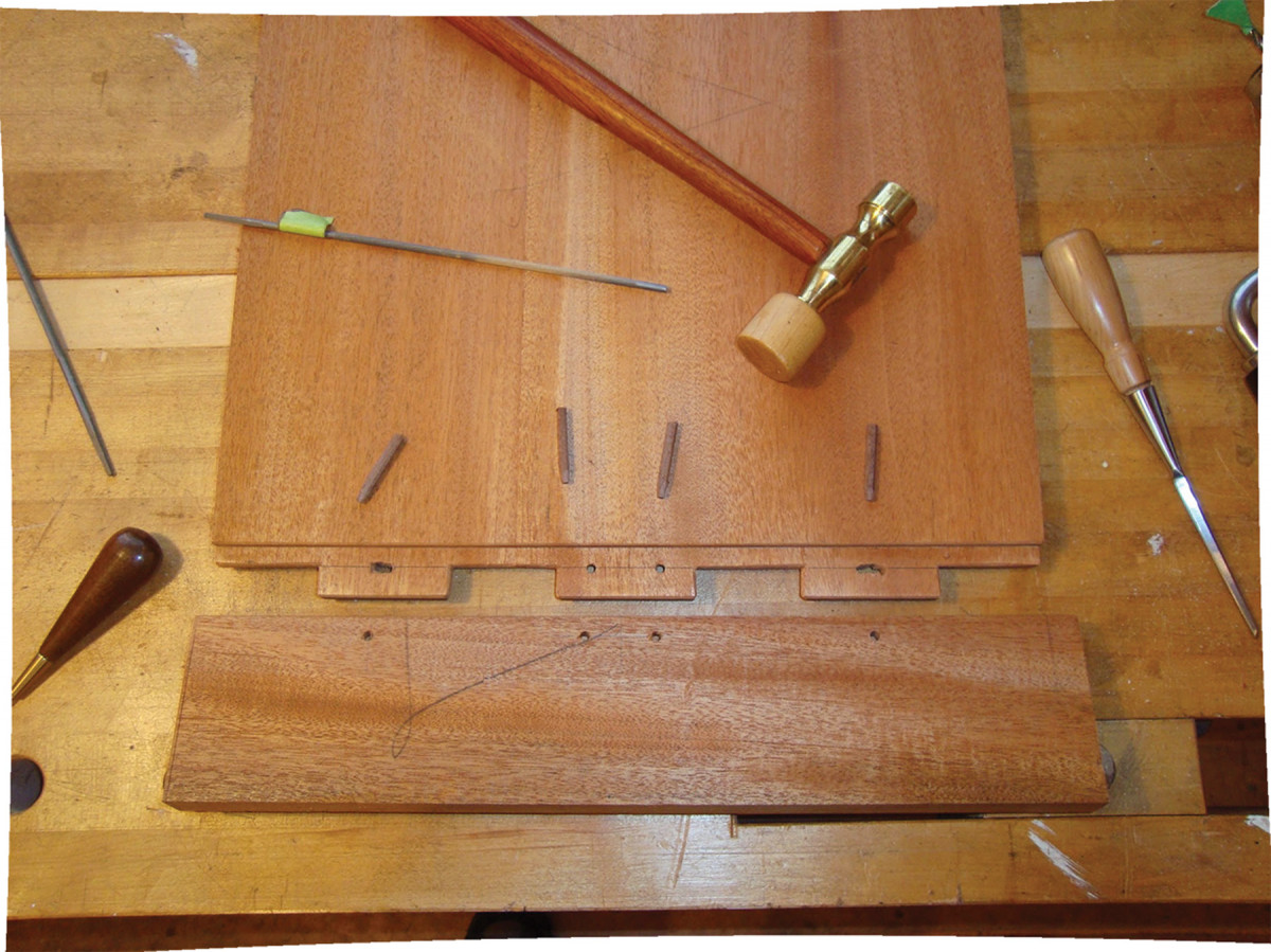
To add decorative details on the ends of the through-tenons (as shown in the opening photo), use a small block plane to bevel the side stretchers and work a beveled curve with a chisel, followed by a spokeshave on the cross stretcher.
Dry-fit the cross stretcher into its mortises on the side stretchers, adjusting as necessary for a right-angle alignment. Then mark the location of the mortise for the tusk. Note that you will overcut this inside the mark toward the shoulder about 1⁄16” so the tusk can do its job. Chop out the mortise. Here, drilling to remove the bulk of the waste might be helpful.
Dry-fit the side stretchers into the legs and check for alignment.
Make the drawbore pegs, 2″-long tusks and wedges. Then, make the leg-to-apron corner brackets, shaping, carving and creating stub tenons for each bracket.
If you wish, you can pre-finish all the components before final assembly (which I recommend – it’s easier to get into corners before they are corners).
Assemble the Base
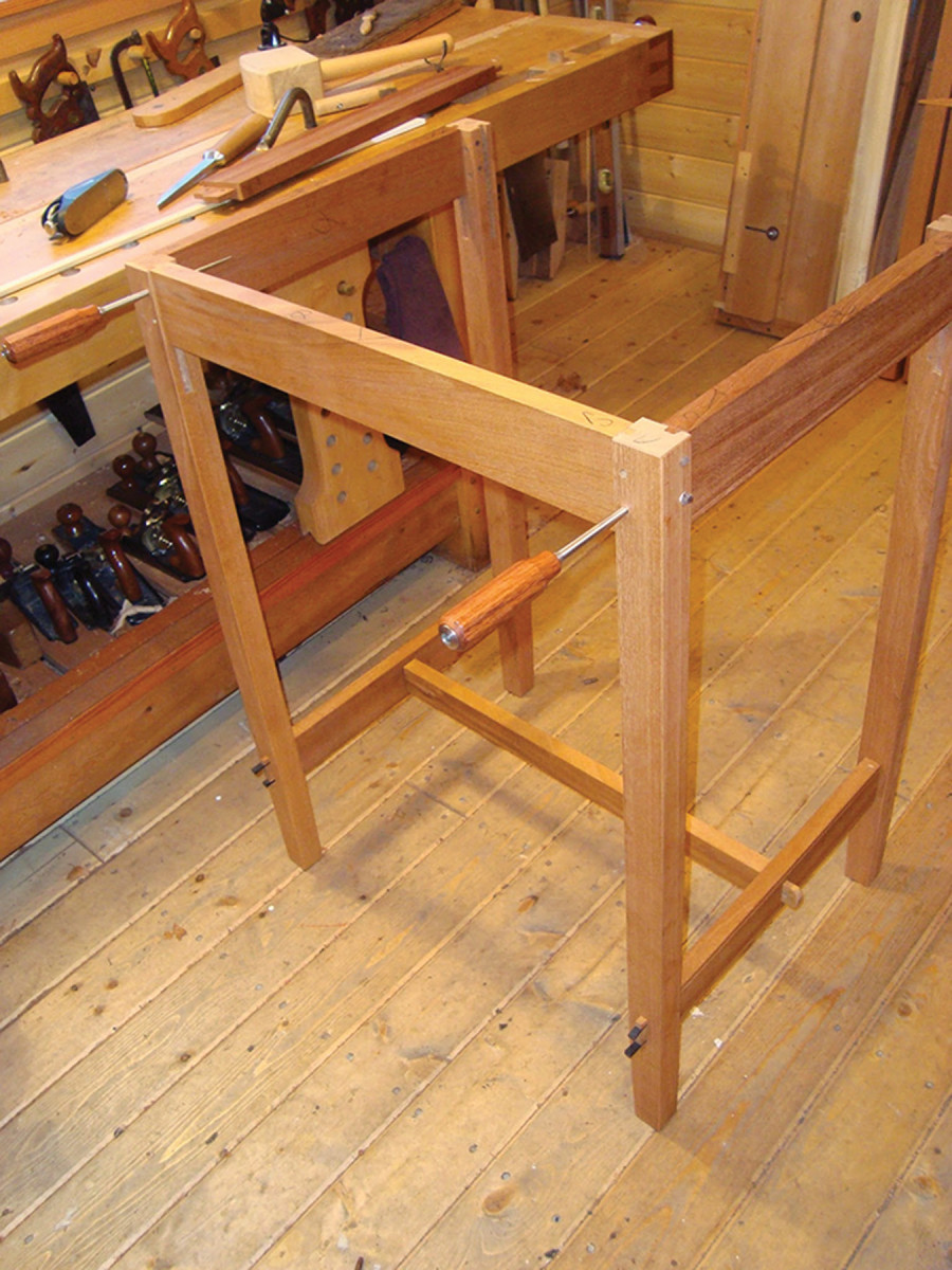
Apron & stretcher. I used drift pins to hold the front apron in place for final pinning. Note the cross stretcher is also installed at this time.
Work on the side assemblies of the base first. Fix the apron to one of the legs by tapping the tenon into its mortise, then draw the shoulder into place with a tapered drift pin. Now drive in the drawbore pegs.
Make sure to put a bit of a taper on the oversized end of the pegs, wax them with a candle, then drive them home. You can clamp the apron in place first if you like, but it’s generally not necessary. Glue isn’t necessary, either.
Now fix the stretcher to that leg by tapping it in place, then tapping a couple of hardwood wedges into the slots. Glue one side of the wedge to help hold it in place through times of ambient moisture level changes. Repeat the process to attach the second leg. (Use hide glue if you want the ability to knock down the base.)
Finally, saw off and trim the excess material on the wedges and pegs. Install the tusk into its mortise. If it loosens when you shake the base, you have permission to add a smidgen of hide glue to hold it in place.
When both side assemblies are complete (you don’t have to wait for any glue to dry) install the front and back aprons and the cross stretcher to one of the assemblies. Then fit the second side to these parts.
Check that the base is square, then glue and screw in a 3″x 3″ triangular block at each corner. These will be used when you screw the top to the base.
Build the Angled Box
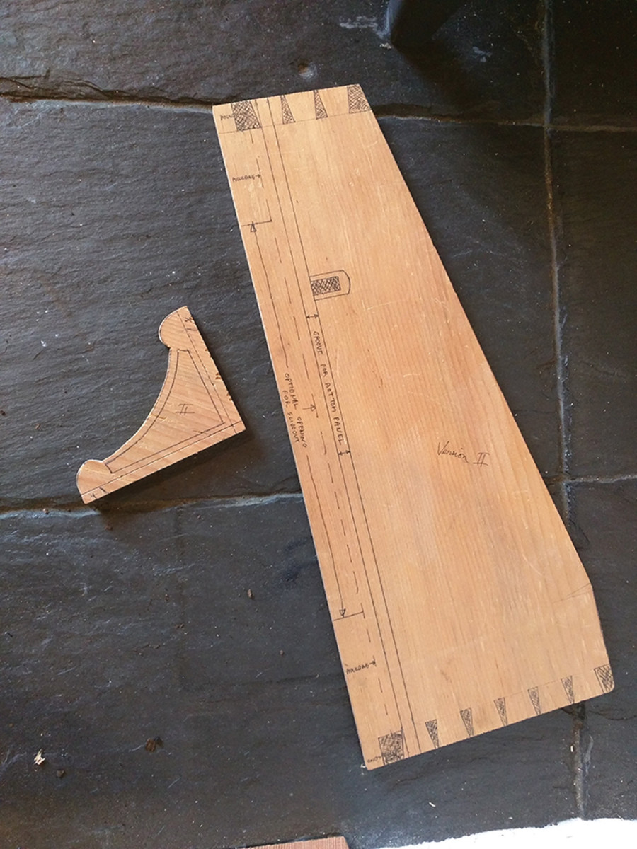
Things to come. I used my story stick to create templates of the box’s side panel and the base’s corner brackets. My side panel template includes the location of the dovetails, the groove for the bottom panel, a mortise for the optional divider and the notch for an optional shelf.
Referring to the story stick for dimensions, make a template for the box’s side boards. From this template you’ll be able to quickly trace the slope angle and mark the location of the dovetails and optional features such as interior dividers and slide-out shelves.
Double-check that the template and the story stick marks for the front and back pieces are the right lengths, allowing an even perimeter margin on the base (which will be filled with cyma transition moulding).
Size the boards to thickness and width, then lay out the lengths from the story stick from a squared end of each board. (For this, the story stick is easier to manipulate than the template.)
Don’t cut the slope angle on the side pieces yet – it is convenient to have parallel edges for laying out.
Notice that the front is about 3⁄16” over-width – this allows for a bevel to be worked on the edge to match the slope angle.
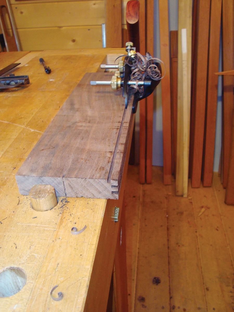
Saw each board to length and clean up the end cuts with a block plane, then mark the baseline for the dovetails. Square these lines all the way around the stock with a knife.
Plow a groove on the inside face of each board to accept the bottom panel.
If you choose to install a divider, refer to your template to lay out and chop the shallow mortise for the divider’s stub tenon.
Using a chisel, work triangular-shaped pocket-screw holes on the upper inside face of the sides and back. The pocket screws will attach the fixed top board to the box.
Cut the Dovetails
Getting close. The notch along the side of the box is for a slide-out shelf. If you don’t want shelves, don’t cut the notches.
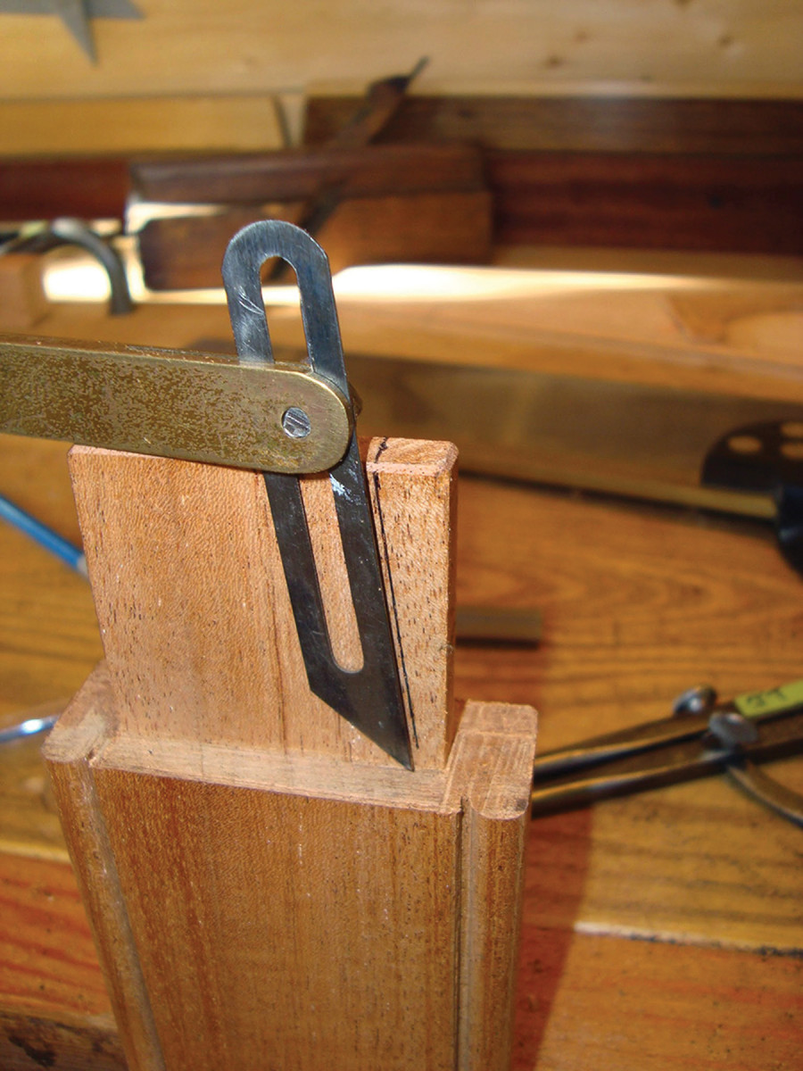
Again referring to the template, mark the location of the dovetails on the ends of the side pieces. If you think you will be making more than one of these desks, it may be more efficient to cut the tails into the template so you can simply trace them on the stock.
Square the marks across the ends of the boards, then use a bevel gauge to mark the tails down to the shoulder line.
Saw out the tails, then chop out the waste. You can drill out the bulk of the waste or use a coping saw.
Using a small ripsaw followed by a plane, work the slope angle on the sides, then trace the pins on the ends of the front and back. Also mark the slope angle on the end of the front to provide a cut line for the bevel you’ll work on its edge. Cut out the sockets for the tails.
Dry-fit the box, checking to be sure all the shoulders fit tightly with the box squared up. Adjust the shoulders as necessary until they do.
Fit the Bottom
While the box is in the dry-fit stage, use pinch sticks inserted into the grooves to obtain the final dimensions of the bottom panel and the interior divider.
From the pinch sticks, lay out the length and width of the bottom panel (which may have to be glued up if you don’t have a wide enough board). Cut the panel to size, subtracting about 1⁄8” from the width to accommodate potential expansion.
Disassemble the box and check to be sure the panel fits into its grooves without binding. Plane the bottom along the edge to correct as necessary.
Plane the top edge of the front board to the marked bevel angle as shown below at center.
If you plan on adding an interior divider, use the pinch sticks to lay out its length, including stub tenons, on the stock. Cut the tenons and check the fits at each end, trimming as necessary.
Assemble the Box
Erase the lines. To match the top of the front board to the side slope, draw the line of the slope on both sides, then across the face. Bevel to the front line, draw marks across the edge, then plane away the waste until the lines disappear.
Pre-finish the interior surfaces of the box and the bottom of the fixed top board. A couple coats of shellac are adequate. I don’t recommend oil; it would smell oily for years every time you open the lid.
On the front and back of the box, brush a light film of liquid hide glue on the cheeks of the pins. Slide on one side.
Slide in the bottom panel and the divider (which you can pre-finish with shellac) and install the second side.
Clamp the assembly together (if necessary) to press the dovetails home. Be sure the structure is square.
Hole in one. Small pins press-fit into holes on the fixed top to secure the fence in place.
When the glue is dry, unclamp the box, then bevel the top edge of the front board to match the side slopes.
Next, true the slopes parallel to one another (test it with a flat board). Plane the slope and front-edge bevel to eliminate any rocking. Next, smooth plane all the pins and tails flush to the outside faces.
To finish the outside of the box, I used Bioshield Hard Oil #9, followed by three coats of amber dewaxed shellac.
Install the finished fixed top board with pocket screws driven by a stubby screwdriver. (You’ll make your life a little easier if you cut and fit the but hinge mortises for the sloped lid before you install this piece.)
In each of the four corners, glue in small corner blocks to accept the screws from the blocks installed in the upper corners of the base.
To make the fence along the back edge of the desk, saw and shape the three pieces that will sit on the small flat (the fixed top) behind the sloped lid.
Join the two sides to the back with a stub mortise and tenon and secure it with glue on the tenon cheeks.
The fence assembly is attached to the flat with small wood pins (dowels or shop-made pegs). To locate the pins, tack in a brad at each pin point, clip it so it slightly protrudes, then press the assembly against the flat to make a mark.
Remove and deepen the marks slightly with an awl, then extract the brads from the fence boards. You now have the center points for drilling holes for the pins.
Sliding Shelves
To add slide-out shelves on each side of the desk, I located the box bottom 3⁄4” up from the bottom edge to accommodate the vertical-grain Douglas fir in my 3⁄4“-thick shelf.
I notched the sides of the box to make room for the shelves, adding 1⁄8” of clearance along the top and sides.
The shelves slide along two bottom runners attached to the base, with a vertical side guide screwed to the opposing side of each bottom runner.
— JT
Make the Sloped Lid
Cheeks & shoulders. I use a moving fillister plane to create the cheeks of the long end tenons of the lid, trimming the shoulder as necessary with a rabbet plane.
Cut the lid and breadboard ends oversize to provide for final trimming to fit.
Lay out full-length tenons on the ends, then cut them with shoulder and rabbet planes. Then, saw the tenons (see image below).
Groove each breadboard end as shown above, then use a mortising chisel to cut the mortises. The groove helps keep the chisel aligned as you cut.
Lay out and drill the holes for the pegs that will capture the tenons.
Movement allowed. The end caps are held securely in place with walnut pegs. Notice that the holes toward either end are elongated to allow the panel to shrink and expand without cracking. I used round rasps and files to create the elongation.
Dry-assemble the breadboard ends to the lid panel and mark the location of the pegs on the tenons. Remove the ends and drill the peg holes in the tenons, insetting them slightly (1⁄32” is enough).
If your lid isn’t made of quartersawn material, consider elongating the peg holes at the outside tenons to allow for movement.
Fit the ends to the panel for final assembly. Glue isn’t really necessary as long as the pegs are tight-fitting – but go ahead and apply a light film to the interior of the grooves and mortises.
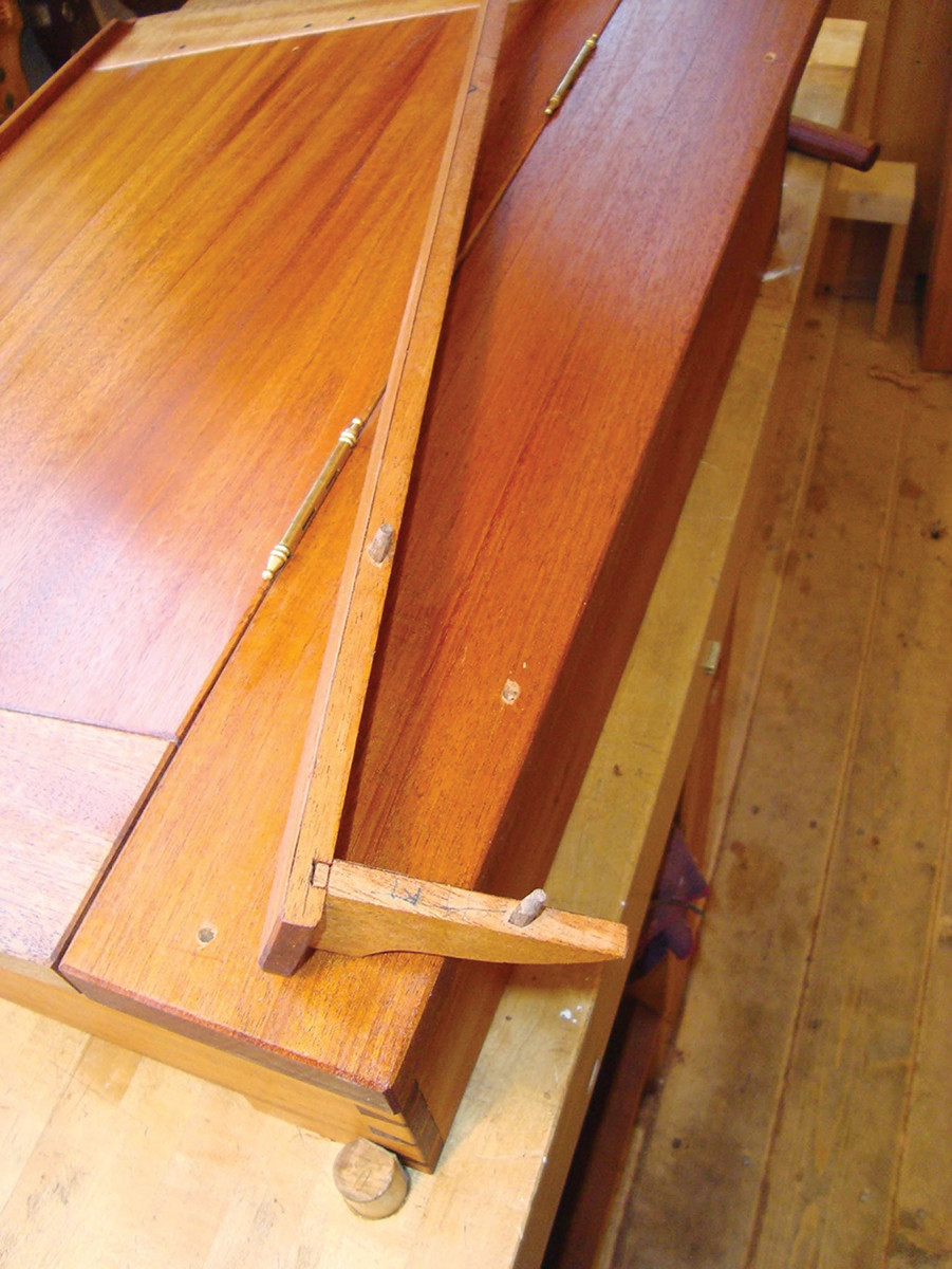
I shaped a simple cyma curve on the ends of the ledger (the strip at the front of the lid) with a chisel, then smoothed the curves with a small spokeshave.
I then worked a shallow rabbet in the attachment side of the ledger to create a bearing surface that will resist downward pressure from elbows.
I used brass escutcheon pins and a bit of hide glue for holding it in place. (Note that the pins don’t bear any load; they just hold it in place so the wood can bear the load.)
Make the Moulding
Speed the plow. With a breadboard end for the lid held upright in a jig, I use a plow plane to make the groove to receive the long tenon.
I stuck the cyma moulding for the box using a moulding plane that creates the full profile. An alternative is to use a pair of hollow and rounds (or, of course, router bits).
Center the box on the base to ensure an even margin, then secure it with screws up through the base’s corner blocks into the box’s corner blocks.
Now work your way around the perimeter, marking, mitering and fitting the ends of the cyma moulding as you go. The final piece is the tricky one because you have to get both miters to fit at once.
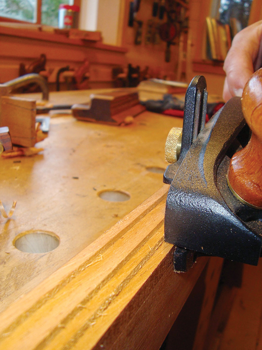
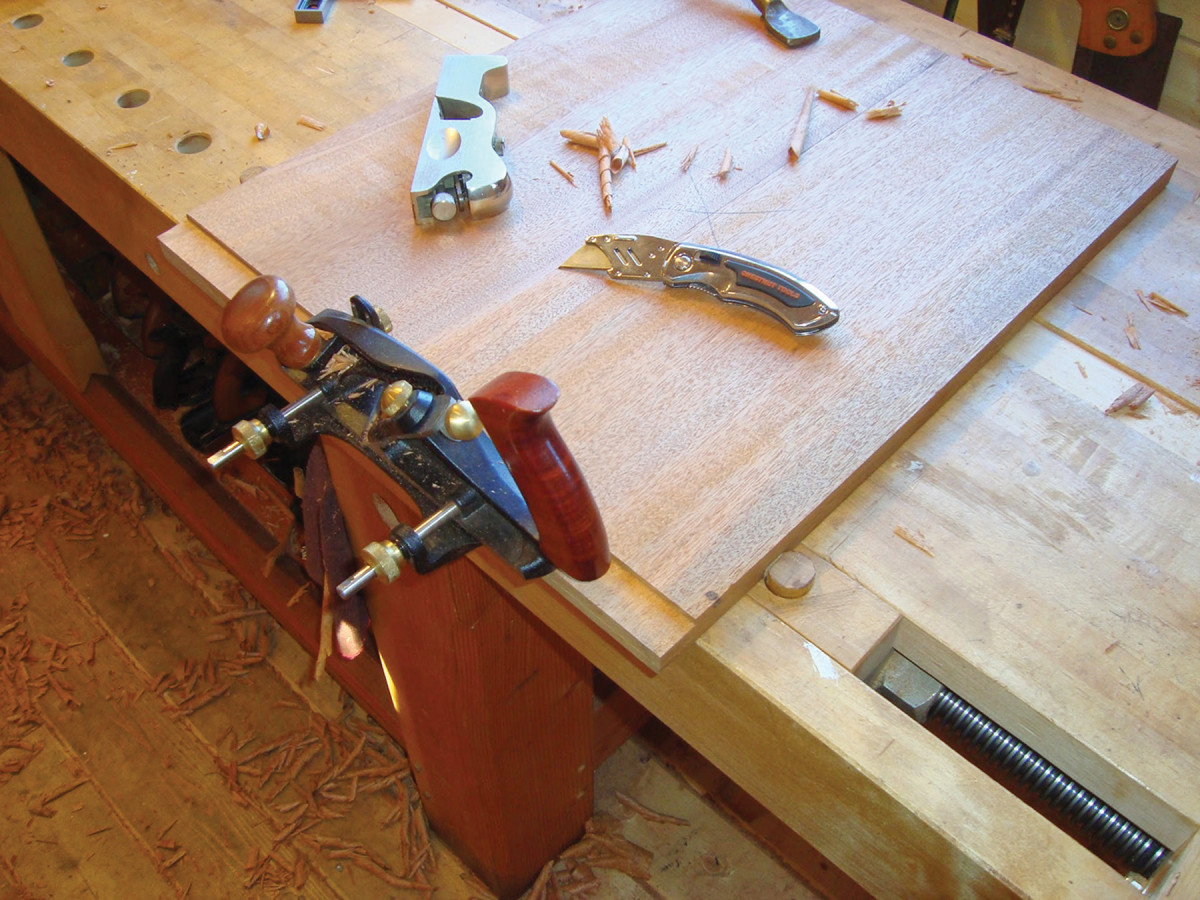
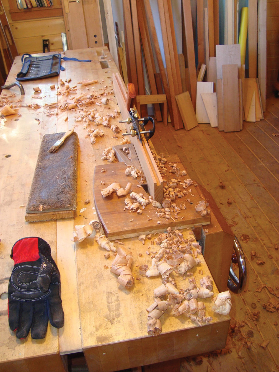
Profiling. I used a skew rabbet plane (technically a moving fillister plane because it has a fence and stop) to remove waste before using a moulding plane to cut a cyma profile.
Overcut the length slightly and block-plane it until it fits tightly at both ends (a shooting board ensures an accurate miter angle).
Install the moulding with brads (I use tiny square nails because they hide better and tend not to split the wood).
Now sharpen your quill pen, and be a stand-up guy or gal and write to your mother (or kids).
Plan: Download a free SketchUp model of this project.
Here are some supplies and tools we find essential in our everyday work around the shop. We may receive a commission from sales referred by our links; however, we have carefully selected these products for their usefulness and quality.


