We may receive a commission when you use our affiliate links. However, this does not impact our recommendations.
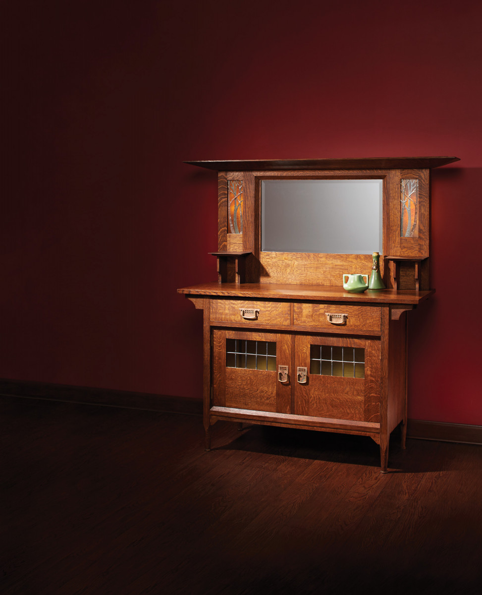
This Harris Lebus classic is a tour-de-force of the English aesthetic.
When we think of the origins of the Arts & Crafts movement in England toward the end of the 19th century, we tend to focus on the revival of handcraft in reaction against the soul-deadening monotony of factory production. Many furniture makers pursued the ideal of handcraft wholeheartedly. But over time it became clear that then, as now, the market for furniture and other wares made to a high standard by hand is limited. Even William Morris complained that he resented spending so much time “ministering to the swinish luxury of the rich” and agreed, late in life, that machines had their place in performing repetitive processes.
While Morris and other idealists looked askance at machines, some workshops eagerly adapted elements of the Arts & Crafts aesthetic to factory production. By doing so, they not only maintained a healthy bottom line, they went a long way toward realizing the movement’s ideal that all homes, not just those of the wealthy, should be furnished with objects that are beautiful and well made.
One of these businesses was Harris Lebus of Tottenham in North London, which made the original version of the sideboard pictured here, as well as numerous variations on the theme. At the turn of the century, Lebus produced bedroom and dining room furniture for an international clientele, in addition to its English market.
With strong lines and a commanding presence, this circa 1903 sideboard is an outstanding example of how this English manufacturer brought graceful utility to homes of the middle class.
Base Cabinet
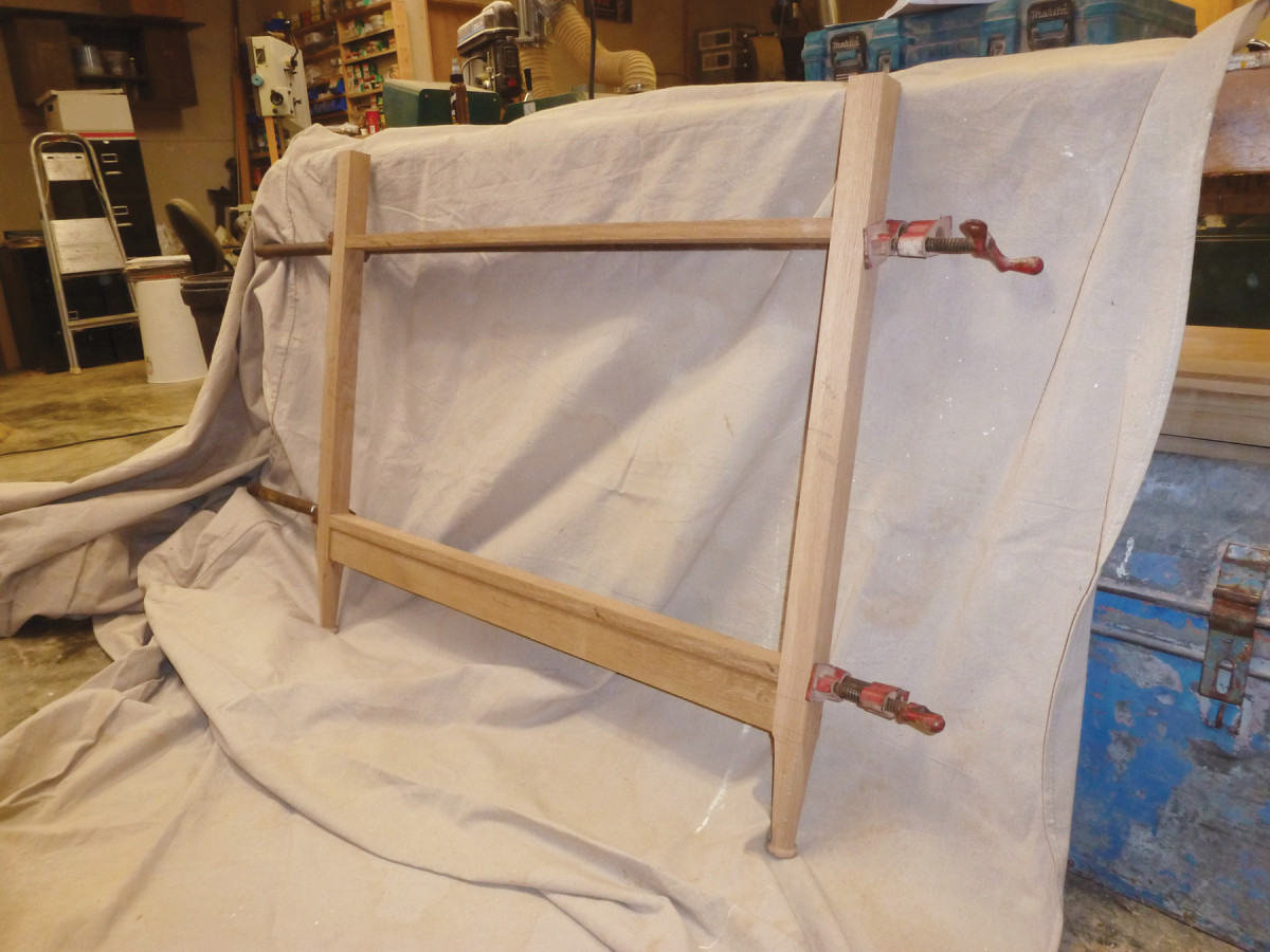
Dry-fit. Clamp the front and back assemblies together and check for square – the success of the rest of the project rests upon it.
Mill and glue up the stock for the top, divider, floor and side panels, leaving all parts oversized in width and length. Clamp the parts in cauls to keep them flat.
Next, mill the legs – again, a little oversized in width and thickness, leaving at least a couple of inches in additional length. Let the legs sit for a few days to allow the wood to move, then mill to finished thickness and width, leaving the extra length.
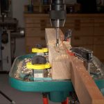
Start by turning the feet, using calipers to keep the diameter of each salient point, i.e. the widest point of the ring-turned foot, the narrow point just above the “ring,” and the spot 21⁄2” up from that narrow point, consistent. After you’ve finished turning, cut each leg to length. (Obviously this cut will be at the top of the leg. Don’t cut off the feet you just turned, right?)
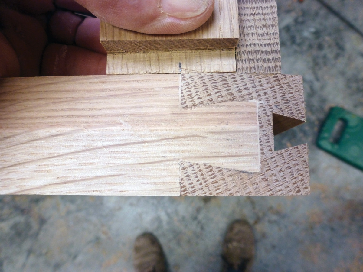
Tail transfer. After cutting the half-lap dovetails, transfer the tail shape onto the legs then chop out the sockets.
Now mark the inside of the front legs for the positions of the mortises for the center rail, bottom rail and bottom trim. Be sure to set the mortises for the front middle rail in 1⁄2” from the back edge of the leg to allow for the 1⁄2“-deep groove that will hold stub tenons for the drawer runners.
Mark the inside of the back legs for mortises that will hold the bottom rail and trim.
Chop or rout the mortises, then cut the tenons. Determine the cut-back of the tenons by standing each tenon on its mortise in the position where it will be when the casework is assembled and transfer the mark directly, then cut with a tenon saw.
When the basic mortise-and-tenon joints have been cut, dry-clamp the front and back assemblies. Use a spacer board or even a 2×4, clamped in place, to ensure that the top of the back assembly is the same width as it is at the bottom.
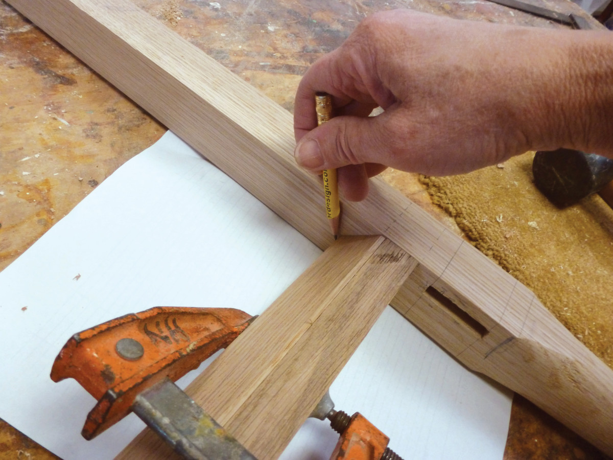
Trim fit. With the trim clamped to the rail, you can accurately scribe its position on the leg, then transfer the mark to the other legs.
Next, measure the distance between the legs and add 13⁄4” to get the overall length of the dovetailed top rails.
Cut these rails to length.
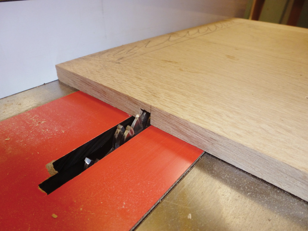
Use a dado stack (or a tenon saw) to lap each end of the front and back top rails with a shoulder 7⁄8” from the end. Now lay out a dovetail at each end, staying about 3⁄16” away from the outside face to help keep the legs from splitting when you try the joints’ fit. As with the front middle rail, set the dovetail in from the back edge by enough that it will not interfere with the groove you’ll rout to hold stub tenons for kickers. Place each top rail (front and back) on its dry-clamped assembly and mark out the pins. Square the line down to the depth of the lap joint and cut with a saw, then chop out with chisels. (You can, of course, unclamp the assemblies now.)
Once you’ve fit each dovetail joint, lay aside the front and top rails.
Cut a 5⁄16“-wide x 1⁄2“-deep groove in the back of the top front rail and the front middle rail for the runner and kicker stub tenons. Position the groove so it will coincide with that of the tenon on the front middle rail.
Assemble the basic carcase dry and clamp it together to check the fit before disassembling and moving on.
Rout the 3⁄8“-wide dovetail slot for the bracket that will go at the top of each leg, setting up the router table so the slot will fall at the center of the leg’s width. Clamp a stop to the fence to finish the slot at 3”; clamping the stop about an inch above the table will allow waste to blow out of the way.
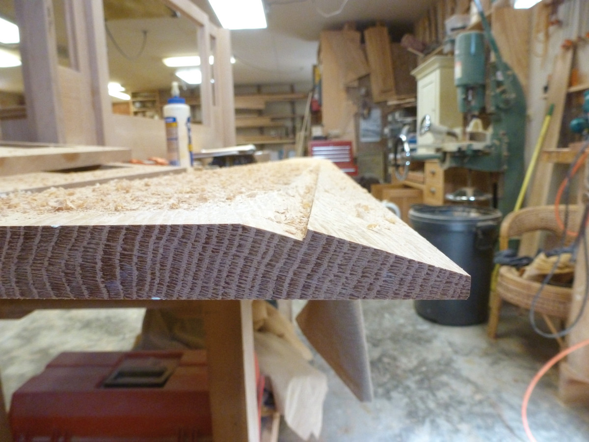
Mill the beveled trim pieces that go above and below the door section, leaving them long. Rip the face edge at 45°, leaving about 3⁄32” of flat area on the front. Cut one end square. Now place one of the bottom front rail tenons in its mortise and clamp a piece of beveled trim in place above it.
Scribe the position of the beveled trim’s top edge on the leg. This will be the position of the top of the dado for the cabinet floor. Transfer this mark onto each of the legs.
Side Panels
Dados. The bottom edge of the dados in the side panels for the cabinet floor must align with the marks on your legs derived from the beveled trim.
Rip the side panels to width and cut to length. The length of the side panels will be the length of the legs minus 6″.
Set up your table saw fence (or router) to cut the dado for the cabinet floor in the side panels. The dado depth should be about half the thickness of the side panels (so about 5⁄16” deep), with the width equal to the thickness of the cabinet floor (3⁄4“). Check that your floor material will fit easily into the dado before you break down the table saw set-up; in this case it is better to err a little on the side of a loose fit, because you’ll be inserting the cabinet floor at a critical time during the glue-up.
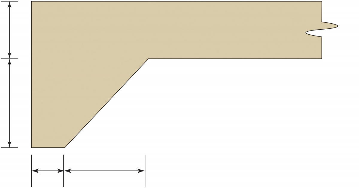
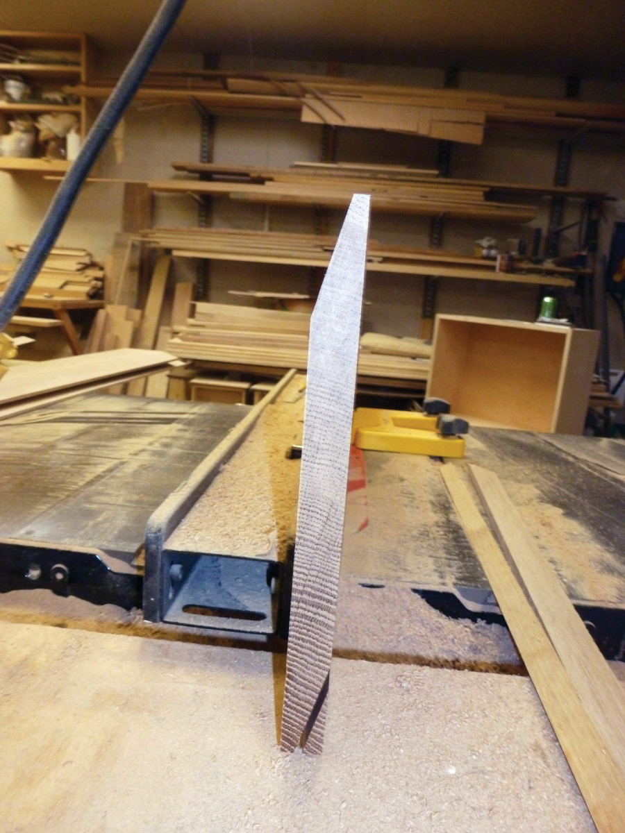
Next, mark out and cut the decorative angled detail at the lower edge of each side panel.
Sand the end panels and the inside edges of the legs, taking care not to sand the areas where there will be joints, lest you mar the fit.
Rip some 3⁄4“-thick scrap to use for spacers that will hold the panel up to create a 1⁄4” reveal between the outside face of the legs and the face of the panel. With the panel resting face-down on these spacers, glue the side panels to their respective legs. Pay attention to ensure that you glue the legs to the panels in the correct positions.
When the panels have dried, clean up any glue residue.
Now cut the decorative front bottom trim. I used a backsaw to cut the angles, then cut out the waste on the band saw. Clean up the cut using the fence on your table saw, paring the area near each end with a chisel.
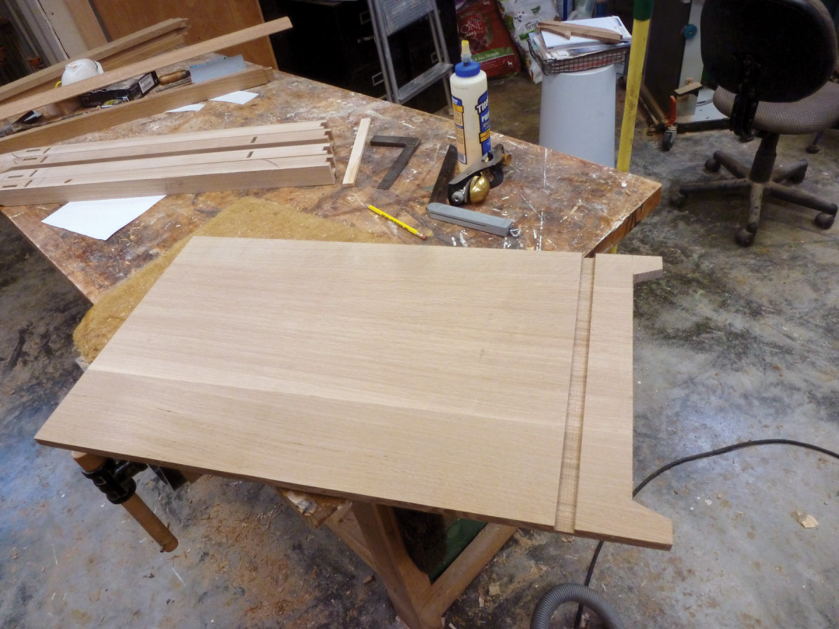
Lighten up. The angled cutouts on the side panels lighten the look of the bottom case.
Now assemble the whole cabinet and clamp without glue. Be sure to clamp the beveled trim in place, too, to make sure everything fits.
Measure from the back edge of the front bottom rail to 5⁄16” in from the back of the back rail; this 5⁄16” space will be rabbeted to accommodate the back. Rip the cabinet floor to this measurement.
Measure between the left and right side panels and add a scant 5⁄8” for the cabinet floor to go into the dados. Cut the floor to this length. To mark out the notches where the floor will fit around the back legs, hold the floor up against the back (inside) edge of the bottom front rail, at an angle, and mark the position of the inside edge of each back leg.
Cut the notches, then tap one side of the cabinet off the dry assembly, insert the floor in the dado, replace the second side, and clamp dry to make sure everything fits.
Sand the front bottom apron and clean up the inside edge of the top rails (front and back) and mid rail.
Arts & Crafts Sideboard Cut List
No.ItemDimensions (inches)MaterialComments
t w l
Base Cabinet
❏ 4 Legs 1 5⁄8 x 1 5⁄8 x 35 1⁄2 White oak
❏ 1 Front top rail 15⁄16 x 1 5⁄8 x 40 1⁄2 White oak 7⁄8″ DBE*
❏ 2 Fr mid & bottom rails 15⁄16 x 1 5⁄8 x 40 1⁄2 White oak 7⁄8″ TBE**
❏ 1 Front bottom apron 5⁄8 x 2 1⁄2 x 40 1⁄2 White oak 7⁄8″ TBE
❏ 2 Side panels 5⁄8 x 16 3⁄8 x 29 1⁄2White oak
❏ 1 Vertical divider 15⁄16 x 19 x 28 White oak Oversized; trim to fit
❏ 1 Div. depth extension 15⁄16 x 15White oak
❏ 4 Base brackets 11⁄16 x 3 1⁄2 x 5 1⁄8 White oak 3⁄8″ DTB†
❏ 2 Bevel trim pieces 1 x 1 5⁄8 x 38 3⁄4White oak
❏ 1 Top 7⁄8 x 22 5⁄8 x 54White oak
❏ 1 Floor 3⁄4 x 18 x 42 White oak Oversized; trim to fit
❏ 1 Floor support strip 3⁄4 x 1 3⁄4 x 38 3⁄4White oak
❏ 1 Back top rail 15⁄16 x 1 5⁄8 x 40 1⁄2 White oak 7⁄8″ DBE
❏ 1 Back bottom rail 15⁄16 x 1 5⁄8 x 40 1⁄2 White oak 7⁄8″ TBE
❏ 1 Runner support rail 3⁄4 x 2 x 42 White oak Oversized; trim to fit
❏ 4 Drawer runners 3⁄4 x 1 x 18 White oak Oversized; trim to fit
❏ 2 Kickers 3⁄4 x 1 3⁄4 x 16 1⁄2 White oak Oversized; trim to fit
❏ 2 Drawer guides 1⁄4 x 1 1⁄2 x 12White oak
❏ 1 Back 1⁄4 x 27 x 40 1⁄4″ oak ply Oversized; trim to fit
Doors
❏ 4 Stiles 15⁄16 x 3 1⁄2 x 17 3⁄16White oak
❏ 2 Top rails 15⁄16 x 2 1⁄8 x 32††White oak
❏ 2 Bottom rails 15⁄16 x 9 x 32††White oak
drawers
❏ 4 Sides 3⁄8 x 5 x 17 1⁄2White oak
❏ 2 Backs 3⁄8 x 5 x 19 White oak Oversized; trim to fit
❏ 2 Fronts 3⁄4 x 5 x 19 White oak Oversized; trim to fit
❏ 2 Bottoms 1⁄2 x 18 x 19 White oak Oversized; trim to fit
Upper section
❏ 4 Outside stiles 1 x 2 7⁄16 x 27 1⁄4 White oak
❏ 2 Outside top rails 1 x 2 1⁄2 x 6 1⁄8 White oak 1″ TBE
❏ 2 Outside bottom rails 1 x 11 3⁄4 x 6 1⁄8 White oak 1″ TBE
❏ 2 Outside end returns 1 x 2 1⁄4 x 27 1⁄4White oak
❏ 2 Center stiles 1 x 2 1⁄4 x 27 1⁄4 White oak
❏ 1 Center top rail 1 x 2 1⁄2 x 31 7⁄8 White oak
❏ 1 Center bottom rail 1 x 7 1⁄2 x 31 7⁄8 White oak
❏ 3 Bevel trim 1 x 1 1⁄4 x 30 White oak Oversized; trim to fit
❏ 1 Top ext. for ctr. sect. 1 x 7⁄8 x 33 1⁄2 White oak Oversized; trim to fit
❏ 1 Cornice 15⁄16 x 8 1⁄4 x 90 White oak Oversized; trim to fit
❏ 1 Dust board 5⁄16 x 9 x 65 White oak Oversized; trim to fit
❏ 4 Candle shelf uprights 9⁄16 x 5 1⁄4 x 6 5⁄8 White oak 3⁄8″ DTB
❏ 2 Candle shelves 3⁄4 x 6 1⁄2 x 8 5⁄8 White oak
“Verify in field” all sizes; *DBE=Dovetail both ends; **TBE=Tenon both ends; †DTB=Dovetail at back; †† Length for both; cut right & left from one board for continuous grain
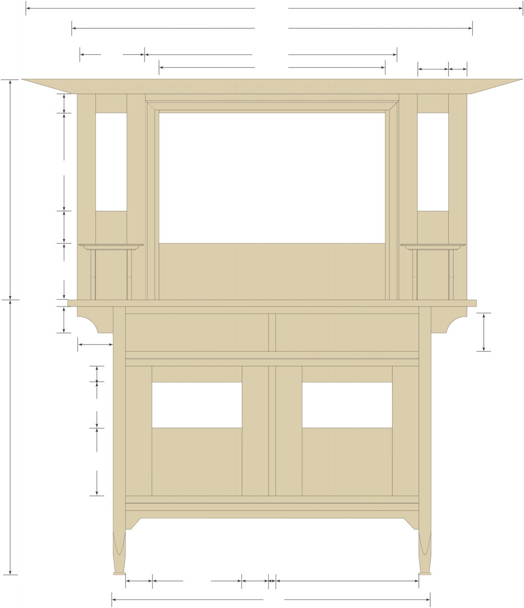
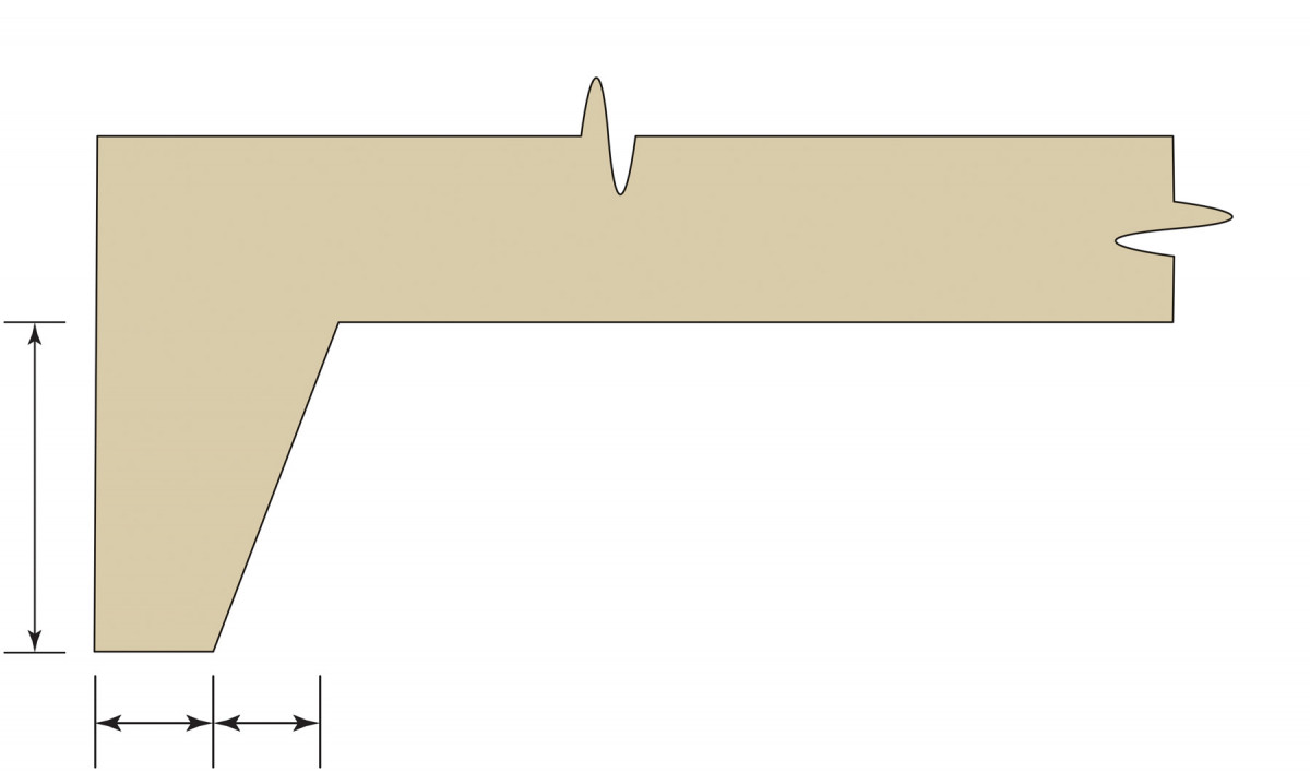
Elevation
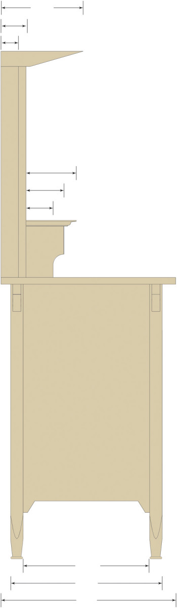
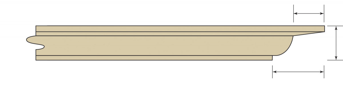
PROFILE
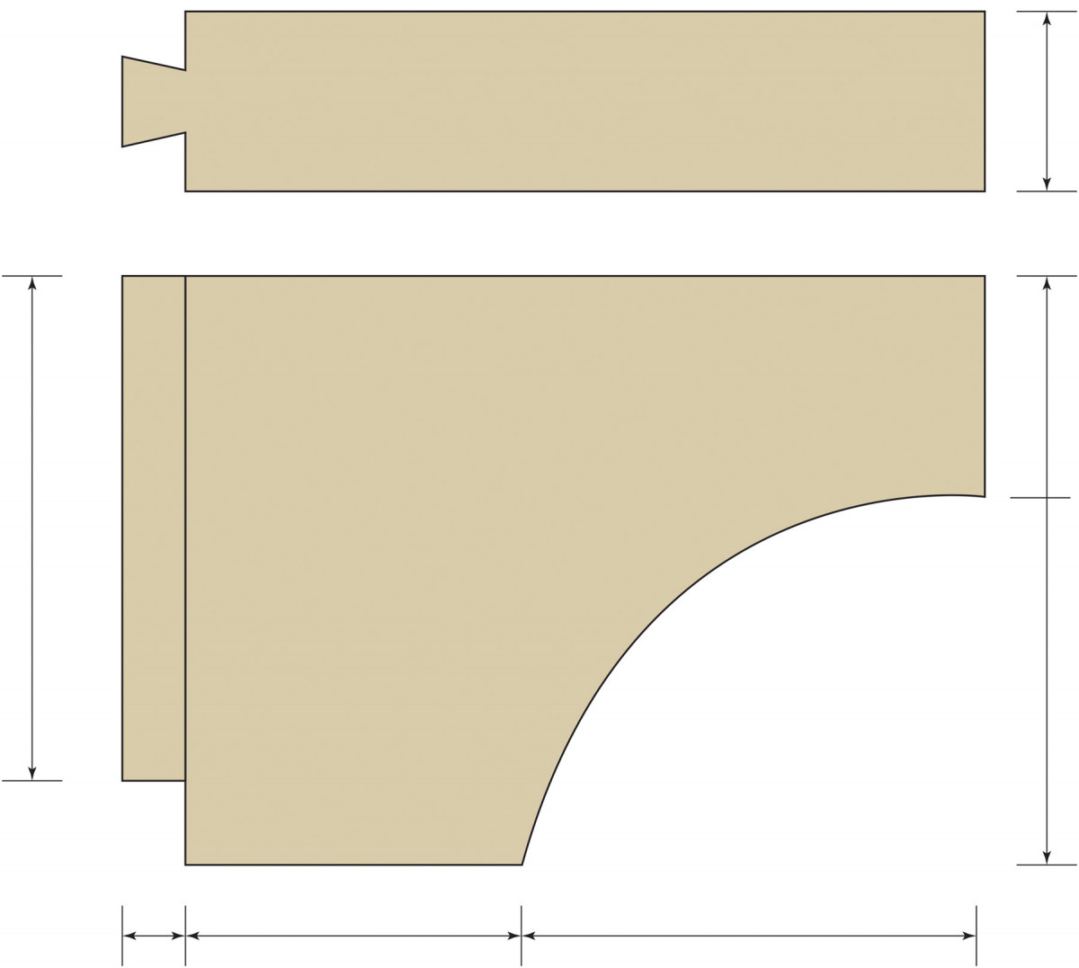
SIDE PANEL detail
FRONT BOTTOM Apron detail
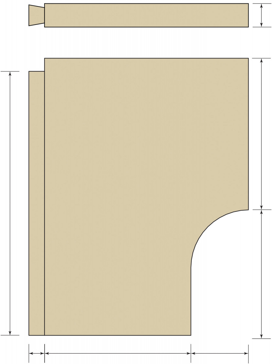
Base bracket
Leg detail
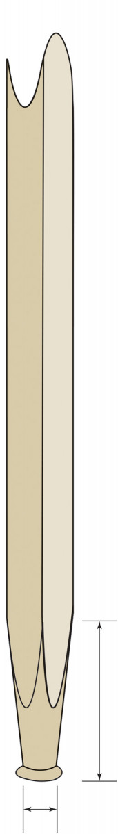
Candle Shelf
Candle Shelf Upright
Assemble the Cabinet

Bottom front. Cut the trim angles by hand then remove the waste between at the band saw. Stopped cuts at the table saw clean things up, followed by chiseling at both ends.
I did the glue-up alone, but it would be easier with a helper. If you’re flying solo, I recommend using Titebond Extend as a sanity enhancer.
Lay one side assembly on your bench and insert the cabinet floor (no glue). Now put glue on the tenons for that side and insert. Put glue on the tenons for the other side and place the other side assembly atop them. Now you should have all the tenons in place. Carefully glue the lapped dovetails and tap into place.
When all the joints are glued, stand the cabinet on your bench and clamp the entire assembly. Check the diagonals across the top and front and adjust as necessary to get the cabinet square. Check across the top rails to ensure there’s no twist. Clean up excess glue.
Supporting member. A 3⁄4″ x 13⁄4″ strip glued and screwed to the underside of the back of the bottom front rail adds support and stiffness.
When the glue is dry, place the case on its face. Rout a 5⁄16“-deep x 3⁄8“-wide rabbet for the back then chop the rabbet corners square with a chisel and mallet.
Turn the cabinet upside down and glue on the floor support strip at the back of the front bottom rail. Clamp it in place, then reinforce the glue with countersunk screws. (Can’t hurt.)
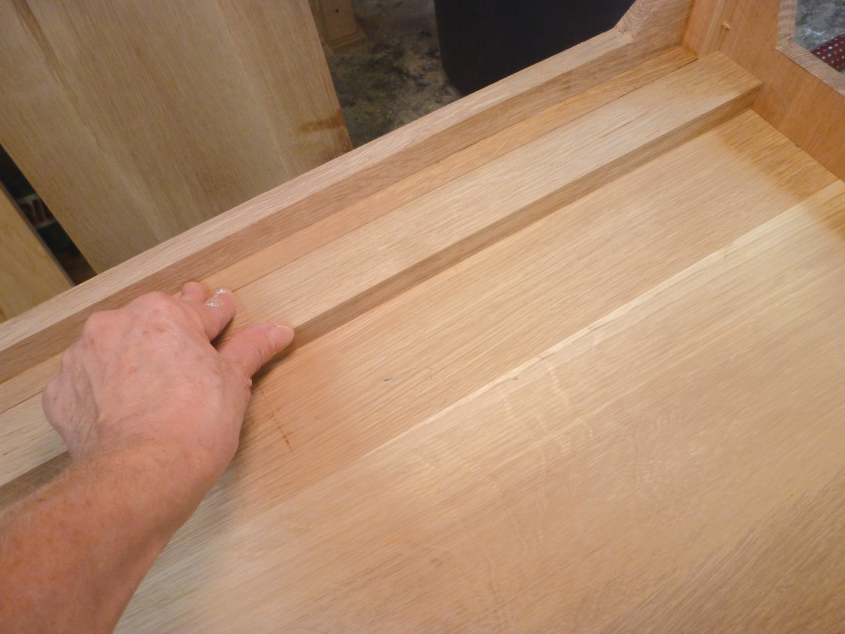
Vertical Divider
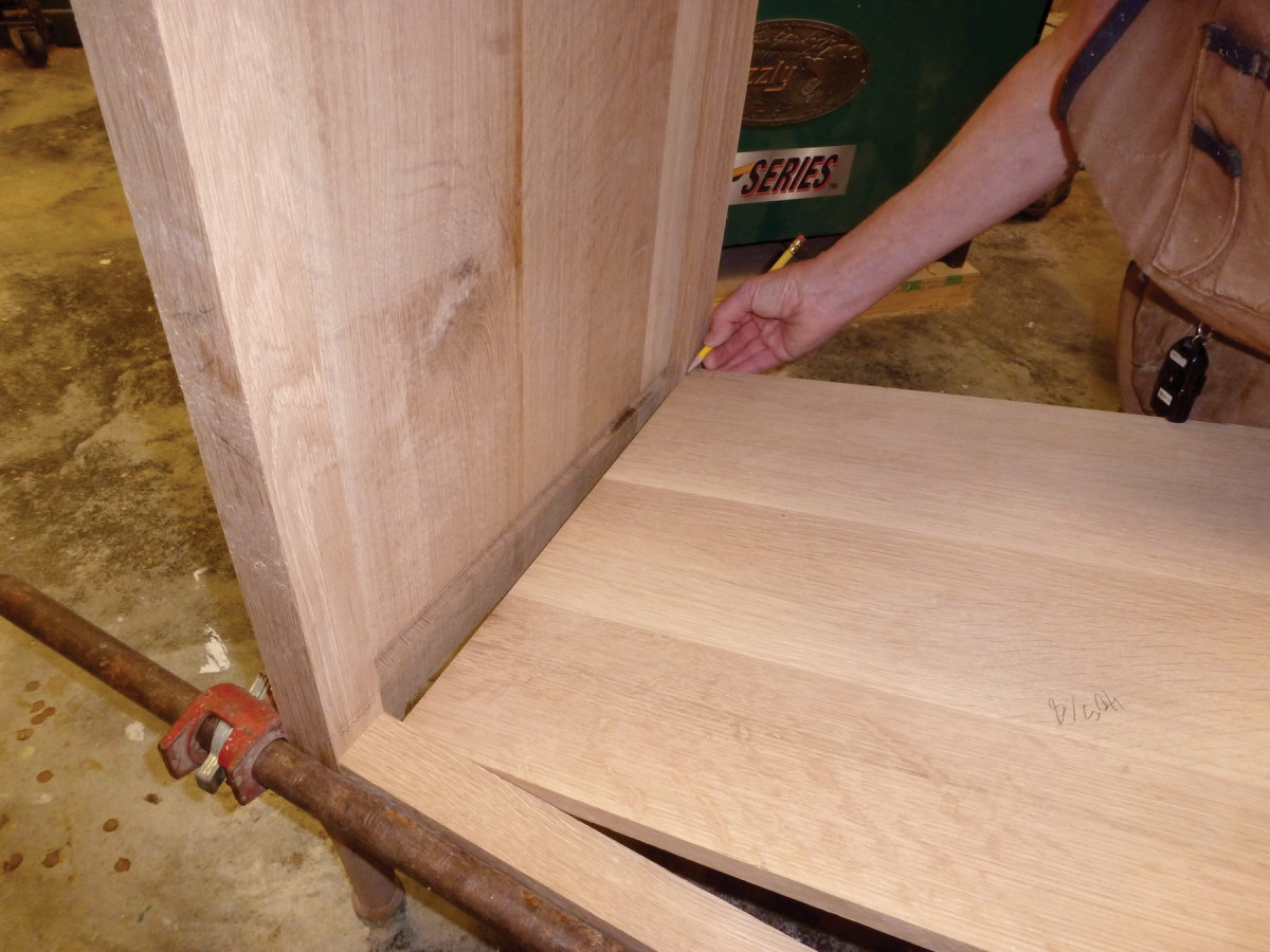
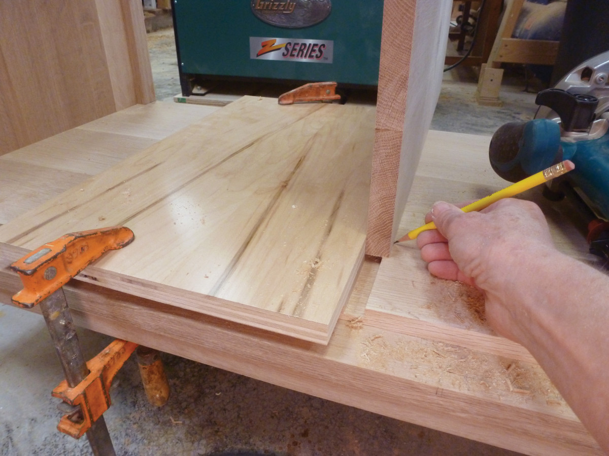
Verify in field. I’m a proponent of, whenever possible, marking off the work rather than relying on measurements. It cuts down on errors. Here, I’m marking the floor for where the leg notches must be cut.
Now stand the cabinet up. Hold the square end of the bottom beveled trim up against the bottom front rail and mark the length. Cut it to length and clamp it place (no glue). The vertical divider will come to the front edge of the flat section on this piece. Measure the distance from the back edge of the cabinet floor to the front edge of this flat section, then rip the vertical divider to this width.
Now mark the centerline of the width of the floor and use a square to lay out a dado for the vertical divider. The dado will be 1⁄4” deep by the thickness of the vertical divider. To get this spot-on, I clamped a straightedge (a piece of 3⁄4” plywood) to the floor of the cabinet along the pencil line of one side of the dado and used a pattern-cutting bit to make the first router pass. Then I held the divider in place against the shoulder of the first cut, marked the position for the other shoulder, and repeated the process so that the dado accommodates the vertical divider’s full thickness.
Two passes. Rout one shoulder of the dado, hold the vertical divider in place to locate and mark the second shoulder, then reclamp the fence and rout again.
Measure the distance from the bottom of the dado to the underside of the top front rail and cut the vertical divider to this length. (Mine was 243⁄4“, but yours may be significantly different.) Insert the vertical divider, tapping it up against the back edge of the front beveled rail. The divider will be notched over the flat part of this beveled rail. Mark the top edge of the beveled rail.
Next, transfer the position of the top and bottom face of the front middle rail onto the divider. Pull the divider back out. Set a marking gauge to the flat section of the beveled rail and transfer this to the lower notch and the middle notch.
Cut both notches and insert the divider to check the fit. Also check to ensure that the back edge of the vertical divider comes to the inside of the rabbet for the cabinet back, trimming if necessary. Remove the vertical divider.
Runner Support Rail Notch
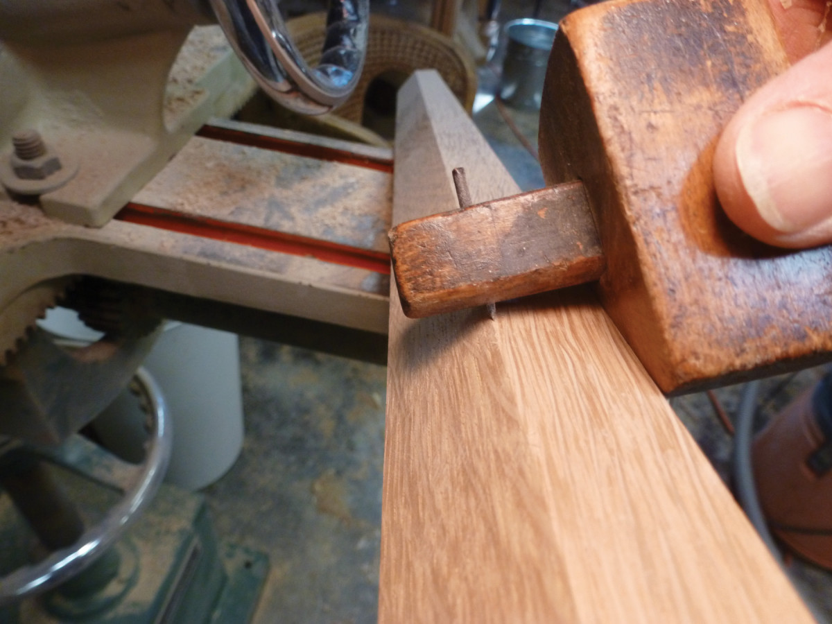
Gauged in. Set a marking gauge off the flat back edge of the top beveled trim, and transfer that setting for the notches in the vertical divider.
Use a framing square to transfer the position of the underside of the front middle rail to the inside edge of each back leg. This is the location for the top edge of the runner support rail. Hold the rail up to the back leg and mark the bottom edge of the notch. Use a marking gauge to scribe the depth of the notch on each back leg. (Add the thickness of the back rabbet to the thickness of the runner support rail.) Saw and chop the notches, then cut the runner support rail to length.
Dry-fit the vertical divider once more and mark the position of the runner support rail on the divider’s back edge. Remove the divider, saw and chop the notch for the runner support rail, and check the fit of both. Sand both the vertical divider and the runner support rail (again, don’t sand the joints), then glue them in place. Measure to ensure that the top of the divider is equidistant from each side at the back and front. Drive a 11⁄4” x #8 screw into the divider through the front and back top rails to secure it in place.
Top Beveled Trim
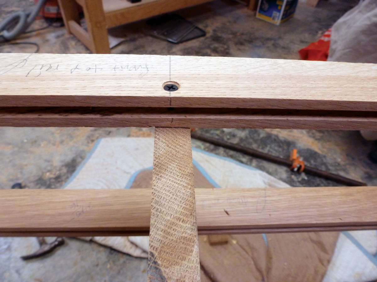
Screwed & glued. After you’ve cut the notches in the vertical divider, glue then screw the vertical divider through the top rails.
To ensure a snug fit, mark the length of the top beveled trim off of the case then cut it to length. This piece gets notched to fit over the vertical divider. Tap it into place and mark the vertical divider’s position.
Use a marking gauge to scribe the flat section and cut the notch at the table saw or with a saw and chisel.
Try the fit and adjust as necessary. Sand the bevel and lower edge, then glue and clamp the trim in place.
Measure for the strip that will extend the depth of the divider at the front between the top and middle rails. Cut it to size and glue in place. (It’s noted as “Div. depth extension” in the cutlist.)
Sand the entire assembly.
Decorative Brackets
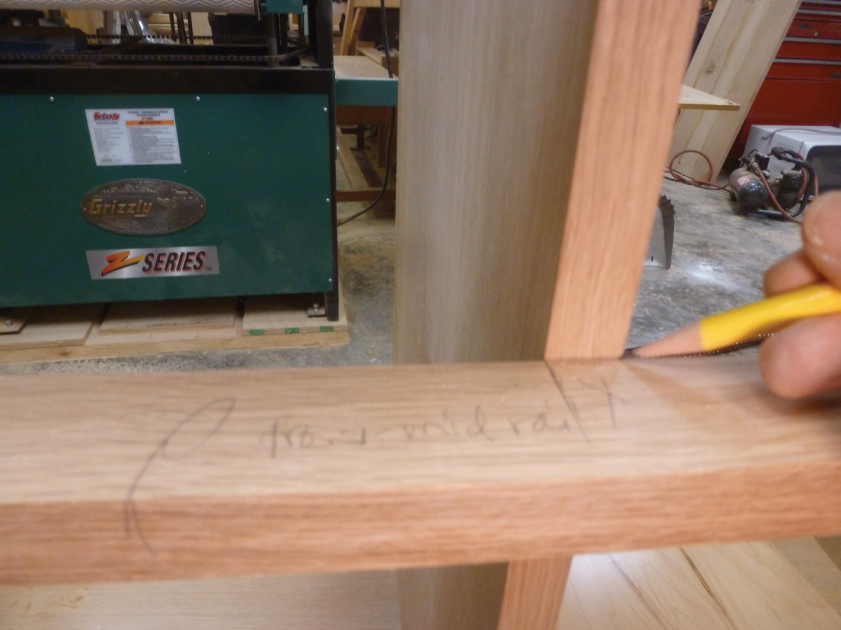
Notch location. With the vertical divider inserted in its dado, mark where it meets the front mid rail.
Cut the bracket stock to size, allowing 3⁄8” for the sliding dovetail on the length. Rout the dovetails on a router table and cut the shoulders flat at the bottom of each bracket.
Make a pattern for the curve in 1⁄4” plywood and use it to mark out the brackets. Cut out the curve and trim it using a pattern-cutting bit.
The brackets are small with scarcely any room for clamps, so I nailed the pattern onto each bracket with two wire nails, then pried it off when finished.
Fair the curves by hand, sand the brackets then glue them in place.
Doors
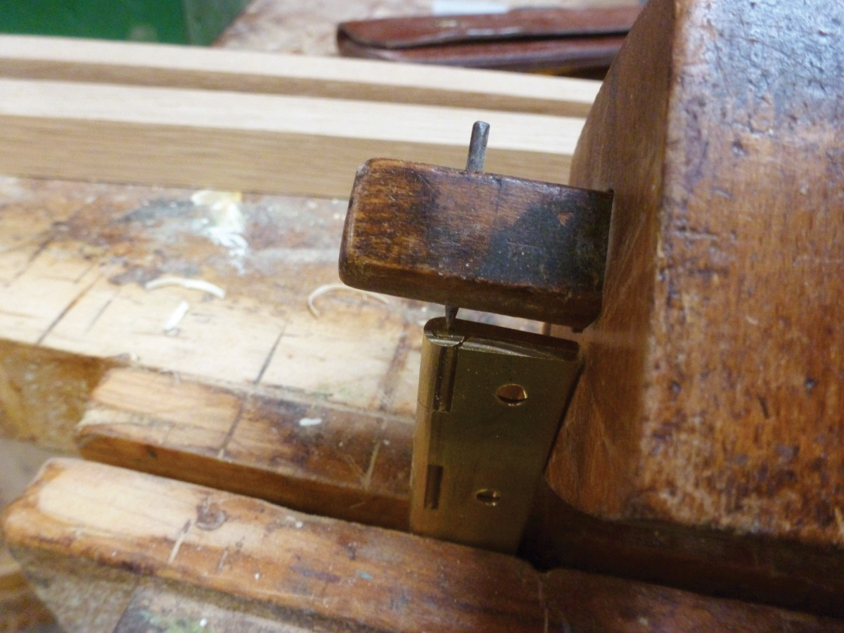
Double up. Set one marking gauge to the hinge leaf width plus half the barrel’s diameter; set the other to the diameter of the hinge barrel, subtracting the desired gap.
Measure each door opening. Mill the parts to thickness and width, then cut the stiles to length. Calculate the length of the rails by subtracting two times the stile width from the width of each opening, then add 2″ to yield a 1″ tenon at each end of each rail. Cut the rails to length.
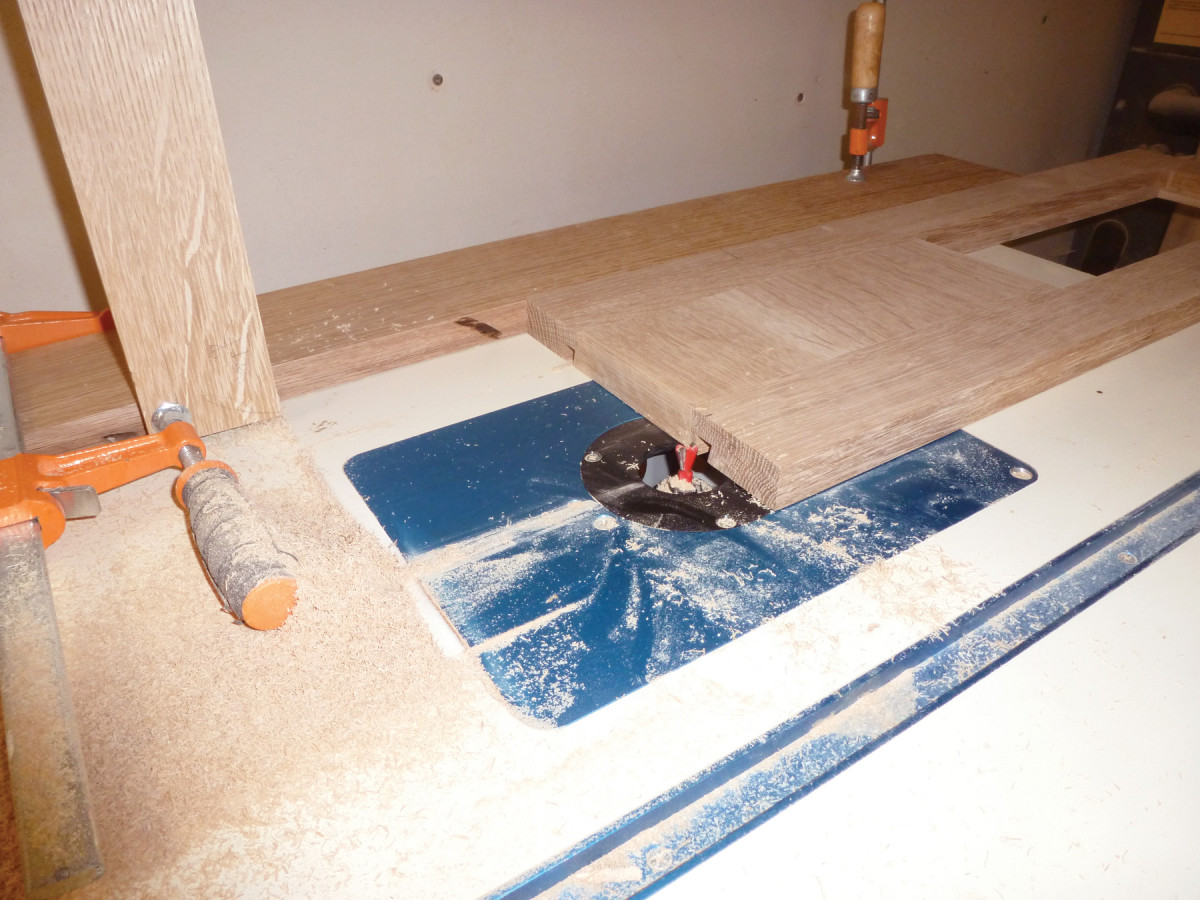
Today, it’s easy to make glazed doors and mirror frames by using a router to rabbet a mortise-and-tenon frame after assembly. So if that’s your preference, go ahead and cut, then fit the joinery, then glue up the doors (check for square and confirm there’s no twist). When the glue is dry, fair the joints as needed then rout a rabbet for the leaded glass panels and square the rabbet corners.
But traditional glazed doors and mirror frames were built from rabbeted stock, which called for stepped-shouldered tenons. If you want to read about achieving that traditional look with modern tooling, see the Online Extras at the end of the article.
Fit the doors to the case, using pennies to shim them up on the bottom front rail. Plane the hinge stile as necessary to get the same margin on the hinge stile side as you have at the bottom. Now trim the top edge so that the doors fit into their openings when shimmed on pennies all around – but at this stage, it’s not a bad idea to leave the fit a little tight at the top and center, in case you need to plane a little more once the doors are on their hinges.
Show the work to the work. Hold the kicker against the front rail and leg to mark it for notching.
Now mark out the doors for the hinges. Because the doors are set back from the cabinet’s face, they will only open to 90°. Note also that the hinges get mortised only into the doors, not the cabinet legs; this is the only way they will open.
Lay out the mortises using two marking gauges: one set to the depth of the leaf plus half the diameter of the hinge barrel; the other set to the diameter of the hinge barrel minus the width of the margin you desire around the doors’ edges.
Cut the mortises (I use a chisel), then screw each hinge in place with a temporary steel screw the same size as the brass screws you’ll insert later.
Set each door in its position on the pennies and wedge them securely using a scrap of wood or shim. Mark the position of the front face of each hinge stile on its adjacent leg. Use a small square to mark the position of the top of each hinge on the adjacent leg. Then remove the doors and use the square to extend those lines across to the back of the legs.
Now set a marking gauge to the sum of the distance between the front of the leg and the front face of the door plus the original hinge leaf setting. (Do the math!) Measure the total height of each hinge and mark the approximate position of each hinge’s bottom on the legs, then use the marking gauge to scribe the back edge of the leaf for each hinge. Saw and chop the mortises.
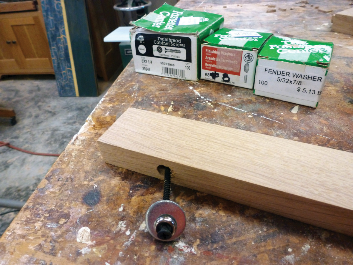
Allow for movement. Drill an oversized hole to accept the screw (with washer) to attach each kicker to its side panel, then cut slots in it for the tabletop fasteners of your choice.
At this point you can either hold the door in position to drill for the first screw then insert it, or remove a hinge from a door and use it to mark and drill the holes for all the hinges. (Holding the door with one hand while drilling and screwing with the other is a bit awkward.) Screw the doors into place with one screw per hinge and adjust the fit as necessary.
Mill the door stops. Mark the positions for rare earth magnets (assuming you are using them as catches) and drill those holes now, using a Forstner bit (doing so while the stops are off the cabinet is far easier than after they’ve been installed). Do not insert the magnets yet! They will go in after the cabinet has been finished. Run a small bead of glue on the door stop, then hold it against the back of the door with the door closed to make sure you have the stop in the correct position. While still holding the stop in position, pull the door open with your other hand, then fasten the stop in place with brads.
Mill glass bead (the strips that hold things in place) for the leaded glass, the art glass and the mirror. Sand but do not fit them until after finishing.
Drawers
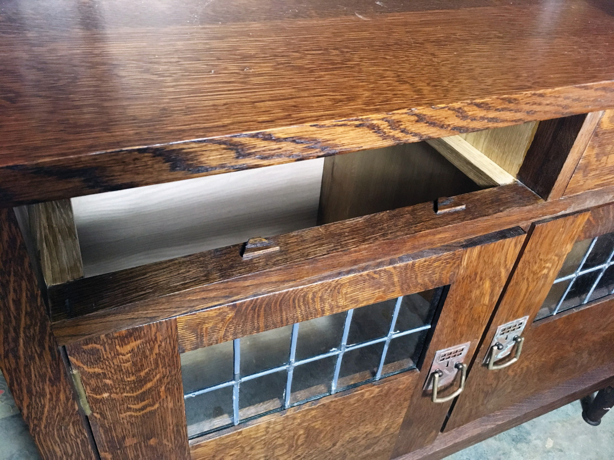
Groovy. Before gluing the drawers, cut grooves in the front and sides for the bottoms.
The runners get stub-tenoned into the front middle rail and rest on the runner support rail, where they are attached using a screw and fender washer with an oversized hole, to allow the front to back movement of the carcase.
The kickers get tenoned into the front top rail and are fastened to the cabinet sides (and center divider) with oversize screw holes to allow the cross-grain panels to move freely.
So tenon each kicker at the front to fit into the groove you routed in the top front rail. Mark each tenon where it will notch around the leg and cut the notch.
Drill an oversized hole toward the back of each kicker through which you will screw it to the cabinet side, then cut slots for the tabletop fasteners that attach the cabinet top the base. (I did this with a biscuit joiner.)
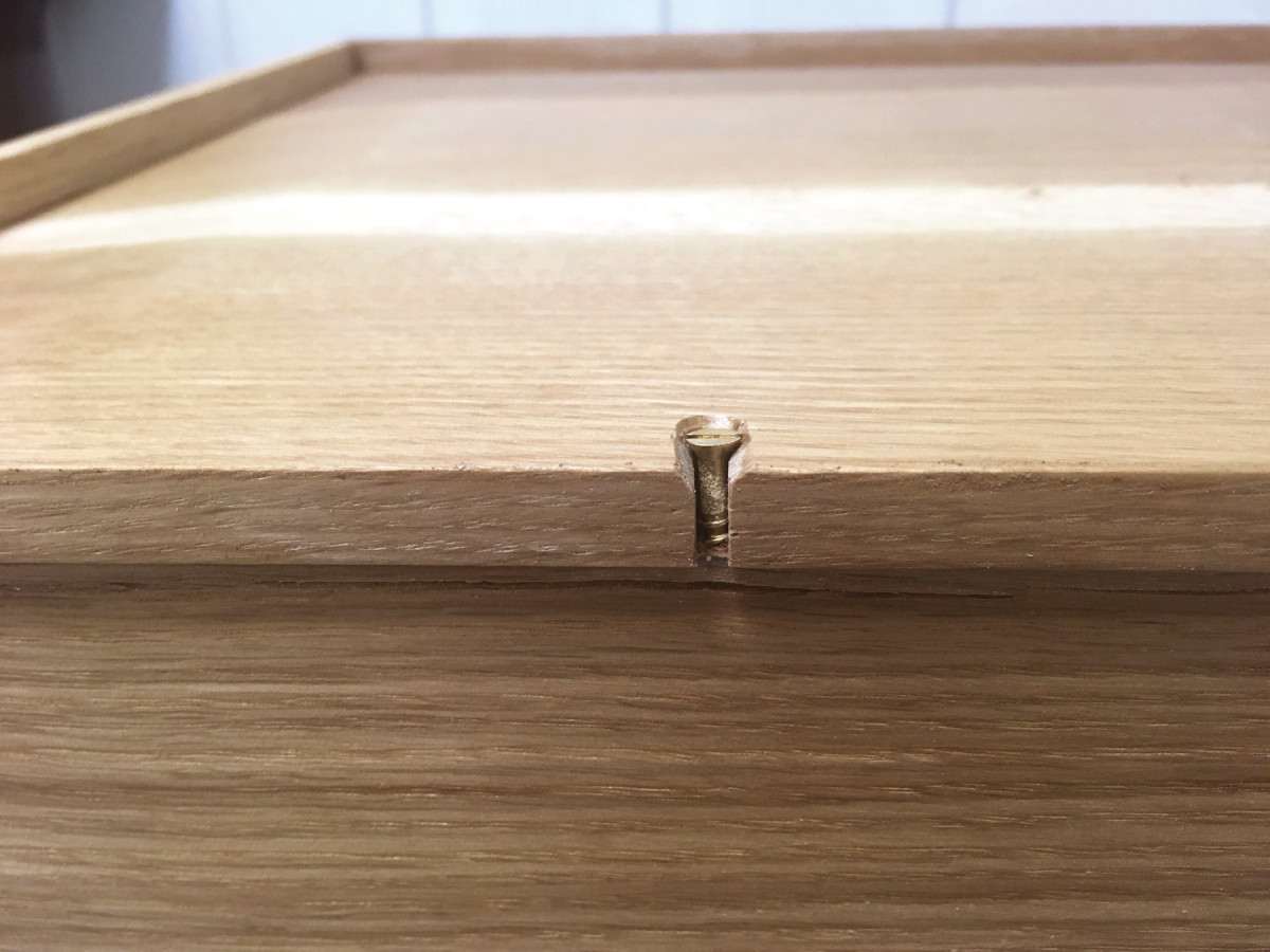
All in the details. Here’s the finished screw slot at the bottom back of the drawer.
Glue the tenons into the front top rail and screw the kickers to the side panels and center divider using 21⁄4” x #8 Twinfast screws, cup washers and fender washers (the washers give the screws enough bearing surface on the oversized hole).
Follow the same basic procedure with the runners, except that they will sit on the center back rail instead of attaching to the side panels.
Mill the drawer parts slightly oversized, then resaw 4/4 stock and glue up panels wide enough to make the bottoms. The grain should run from side to side so that the drawer bottoms don’t shrink right out of their grooves.
Trim the drawer fronts to just fit inside their openings, and plane the top of each drawer side so that it will slide into position.
Now dovetail the drawers (half-blinds at the front, through-dovetails at the back). I usually set the depth to leave about 1⁄8“-5⁄32” at the front for half-blind dovetails.
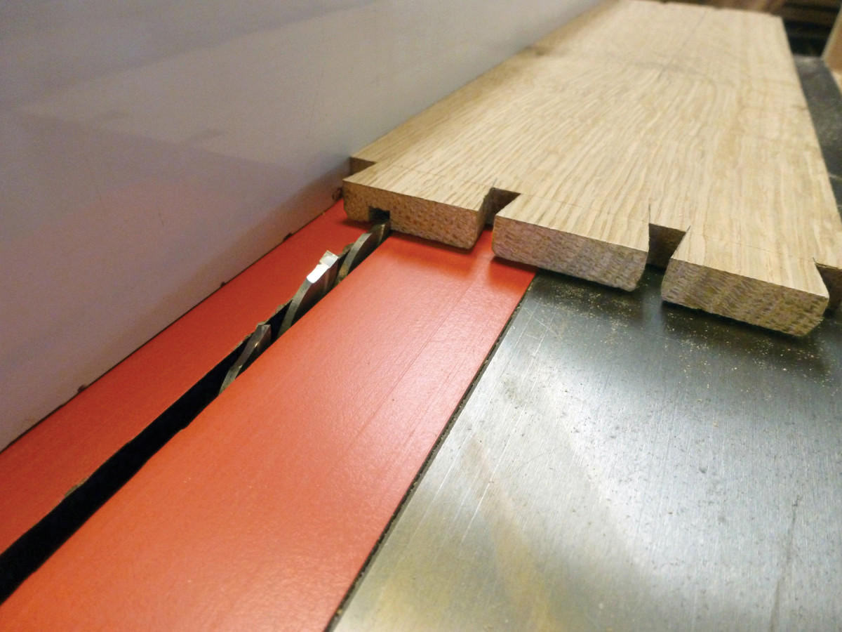
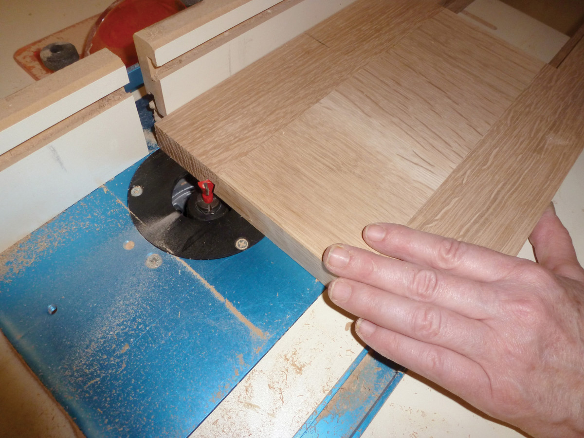
After you fit the joints, groove the sides and drawer fronts on the table saw.
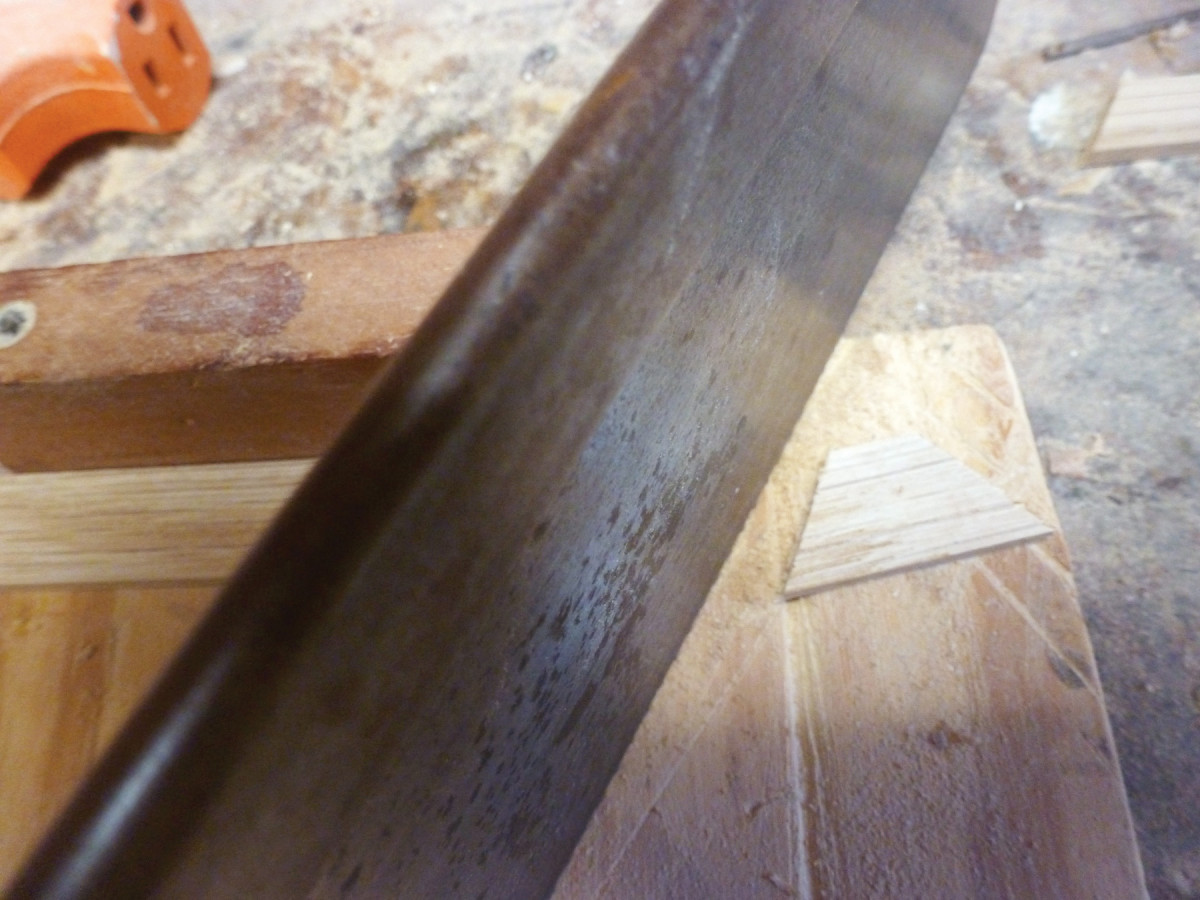
Saw stops. I sawed two angled stops for each drawer from a thin strip of oak.
The height of the blade should be about half the thickness of the drawer sides, with the bottom edge of the groove about 1⁄2” up from the lower edge of the drawer sides and fronts. After you’ve made each of the first cuts, move the fence over by about 1⁄8” to widen the groove to about 1⁄4“. Now rip the backs to the same setting, so that they will sit just above the groove.
Glue up the drawers and check for square and twist.
While the glue dries, plane their bottoms to 3⁄8” thick. Measure the drawers to get the dimensions for the bottoms (don’t forget the grooves!), then rip and cut them to length. Because the grain runs side to side, the length should be a hair under the sum of the inside drawer width plus two times the depth of the groove. The width (front to back) should allow for the bottom to seat fully in the front groove while overhanging the drawer back by about 1⁄16“.
With the bottoms cut to size, bevel the front and side edges to fit the grooves. I did this at the table saw.
Clean up the drawers and plane the sides as needed to fit their openings.
Now drill and countersink two holes through the drawer bottoms, then square a line from the outside edges of the hole to the back of the drawer bottom. Saw a kerf along each line and remove the waste. Use a paring chisel to extend the countersink bevel to the back edge. These slots allow you to screw the bottoms to the back, allowing for seasonal movement. Insert the bottoms and screw them into place.
Full stop. Here’s what the stops look like after installation (shown here after the finish has been applied).
Saw the drawer stops from a thin oak strip, then glue and pin them in position.
Ease the edges to remove splinters.
The drawer stops go on the middle front rail immediately behind the inside of the drawer face. Measure the thickness of the drawer face and draw a pencil line on the rail as a rough guide to where the stops will go. Apply a dab of glue to the underside of two stops (don’t use a lot of glue, because that will cause the drawer stop to stick to the drawer) and place them so the front edges are just in front of this line. Now insert each drawer, pushing it carefully in until the drawer face is flush with the carcase face. Leave them in place until the glue dries, then gently remove the drawers. Drill and pin the stops in place with two pins in each.
After finishing the sideboard (after you’ve made the upper section), screw the plywood back in place.
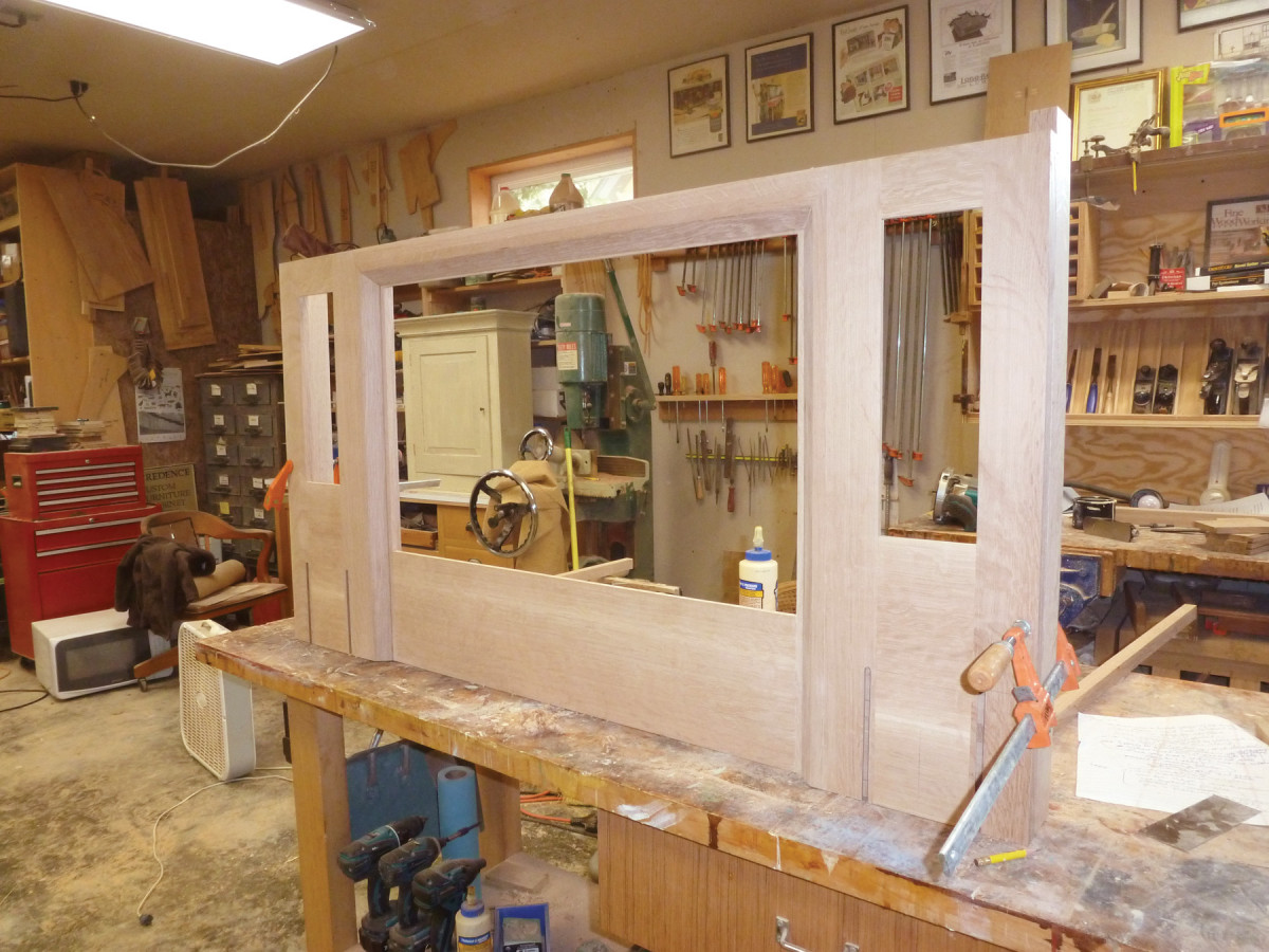
The Upper Section
In position. Use strips the same thickness as the center frame to prop the two outside frames in place for marking and measuring.
The top consists of three simple frames joined together, then decorated with beveled trim and candle shelves. The cornice is added last.
Mill the frame parts to thickness and width, then cut the outside stiles and end returns to length.
Mark out the mortise positions and cut the joints. The mortises should be set back 5⁄16” from the face; each should be 5⁄16” wide by a little over 1″ deep.
Now cut the rails to length, allowing for a 1″-long tenon at each end.
Use a mortised stile to set up a dado stack in your table saw to cut the face-side cheek of the tenons. Cut all the face-side cheeks. Then adjust the dado blade for the back cheeks and cut.
Transfer the mortise positions onto each tenon, then saw them to fit.
Glue and clamp each frame.
When the glue is dry, fair the joints, then rout a 3⁄8“-wide x 3⁄4“-deep rabbet around the inside edges of each and chop the corners square.
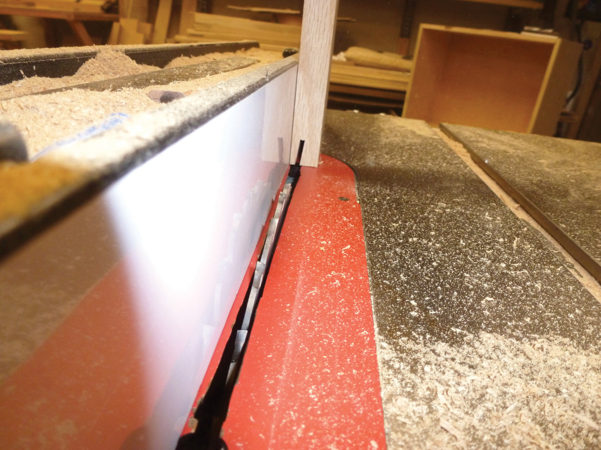
Now clean up the inside edges. Plane the bottom of each frame flat if the stiles are protruding at all, then trim each one to precisely the same height by running the frames’ lower edges against the table saw fence.
It’s time to measure for the beveled mirror and art glass. Be sure to allow at least 1⁄16” margin in the width and height respectively in case of any irregularity. Order the glass now so that the maker will have time to fabricate it while you complete the rest of the piece.
Rip two strips to the thickness of the center frame and use these to prop up the side frames level with the one in the center. Each side frame will overlap the center frame by about 1⁄2“. Lay the side frames in place on top of the center frame.
Mark the position of the depth extension rail that goes at the top of the center frame, fit snugly between the outside frames. Cut the rail to length, and glue in place with clamps.
While the depth extension rail is drying, rout the slots for the candle shelf dovetails. I used two set-ups on my router table – one with the fence for the side closest to the edge of each frame, then I removed the fence and clamped a straightedge to the table to get the far slot in the appropriate position.
Once the slots are cut, clean up the frames, then glue and clamp the left frame in place, taking care to position it so the reveal between its inside edge and the edge of the center frame (the one that holds the mirror) is consistent.
Next, mill the upper beveled trim at 45°, leaving each piece overlong. Miter the top of the left piece and the left end of the top piece. When the miter fits well, cut the left piece to length. Sand or scrape it smooth, then glue in place using pins or brads to secure it.
Now glue and clamp the right frame in place. Miter the right end of the top piece of beveled trim, clean up any machine marks, then glue and pin or nail it in position. Finally, repeat the process with the right piece of beveled trim.
After the glue dries, stand the frame up on your bench (a second person is helpful for this) and measure for the side returns, then glue them on. Make sure they are square to the face of the frames.
Candle Shelves
Candle shelves. The slots for the candle shelves’ vertical supports take two set-ups. For the slot close to the edge, use your regular fence.
Mill the uprights, then rout the sliding dovetail on the back of each one. Saw the decorative shape, then use a router with a pattern bit to clean each one up.
For the far slot, make an ad hoc fence by clamping a length of scrap to the table.
Trim off the stopped portions, then sand or scrape them and glue in place, making sure that each one is square to the frame assembly.
Cut the shelves to size. Cut a beveled kerf on the front and two sides of each shelf on the table saw with the blade set at 11⁄16” high and 7°. Mark the profile on the end of one shelf to use as a guide.
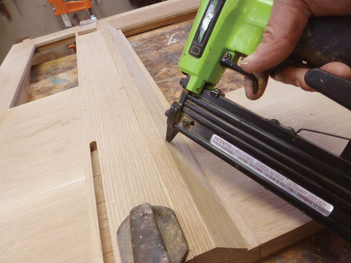
Pin it. Set up the panels on the scraps again, clamped in place. Then glue and pin the beveled trim to the side frames.
For the second cut, set the saw blade at 90° to produce a 3⁄32” high kerf at 11⁄8” overall from the fence (be sure to include the thickness of the saw blade when you set the fence!).
Stand up. With the upper section standing up on the bench, glue and clamp the returns in place.
Next cut kerfs with the blade raised a little higher and the fence a little closer to the blade, to nibble away the waste close to your profile line. Use a block plane or finger plane to form the curved part of the moulding on the front and sides of each shelf.
Sand the shelves and secure them in place with a little glue and brads.
The Cornice
Kerfs. The table saw cuts remove the bulk of the waste for the candle shelf profile.
It’s finally time to top things off, so mill the cornice stock to width and thickness.
 Set your table saw blade to 16° and rip a bevel along one long edge.
Flip the stock over and rip the same bevel on the opposite edge and face.
With the stock on a bench or in a vise, rout a rabbet to accept the dust panel – a thin piece of oak that sits in this rabbet to form a solid top for the cornice. Be sure to keep the base of the router resting firmly on the beveled part of the moulding to ensure the rabbet is parallel to this angle.
Sand the front edge – the top section that shows in front of the dust shelf – and the broad lower face that angles up.
Next you’ll determine how much of the flat part of the bottom bevel will sit over the three-part frame (I had about 11⁄2” relative to the center section) and mark this in pencil near each end of the longest piece of cornice moulding, then extend the line along the length.
Heavy bevels. The cornice gets a significant bevel along its front and back edges. Cut one, then flip the stock and cut the same bevel on the opposite edge.
To determine the positions of the miters, it’s easiest if you have someone who can help you hold the pieces firmly in place. Cut the miter at one end of the long piece and set it on the frame assembly so that the overlap coincides with your pencil line. Holding it in place, mark the position for the miter at the other end. I suggest that you cut the second miter a little long, then finesse the fit in conjunction with the mitered returns; that way you will avoid cutting the long piece too short. (Note: You can have as little or as much overlap as you wish, as long as there’s enough to support the cornice and keep it stable.)
Now you are ready to cut the miters on a sliding miter saw or a table saw with a crosscut table. I shimmed the stock with scrap so that the lower beveled portion was sitting squarely on the saw table in the same orientation as how it seats on the finished upper section. This allowed me simply to cut a 45° angle at each corner.
Drill pilot holes in the center section so you can tack the moulding in place with screws while fitting the miters. Apply glue to each miter, then use tape or clamps to hold the joint closed while the glue dries. (Because this is a delicate joint, leave the miters clamped overnight.)
Clean Up the Joints
Dust panel. The dust panel sits in a flat on top of the cornice. To cut that, I used a rabbeting bit in the router, with the fence registered off the edge.
Screw the mitered moulding firmly into place on top of the three-part frame.
Resaw or plane quartersawn stock for the dust panel to sit in the rabbet at the top. Cut a couple of spacer blocks to support the dust panel in the center, drill slightly elongated holes in the dust panel to allow for wood movement and attach to the cornice with screws.
The original sideboard is stained a warm medium-brown. To finish this one, I started with a coat of honey amber Transtint dye, followed by Minwax Early American oil-based stain. The next day I brushed on a coat of amber shellac and finished with a coat of paste wax. PWM
Nancy designs and builds custom furniture at her shop near Bloomington, Ind.
Here are some supplies and tools we find essential in our everyday work around the shop. We may receive a commission from sales referred by our links; however, we have carefully selected these products for their usefulness and quality.