


We may receive a commission when you use our affiliate links. However, this does not impact our recommendations.
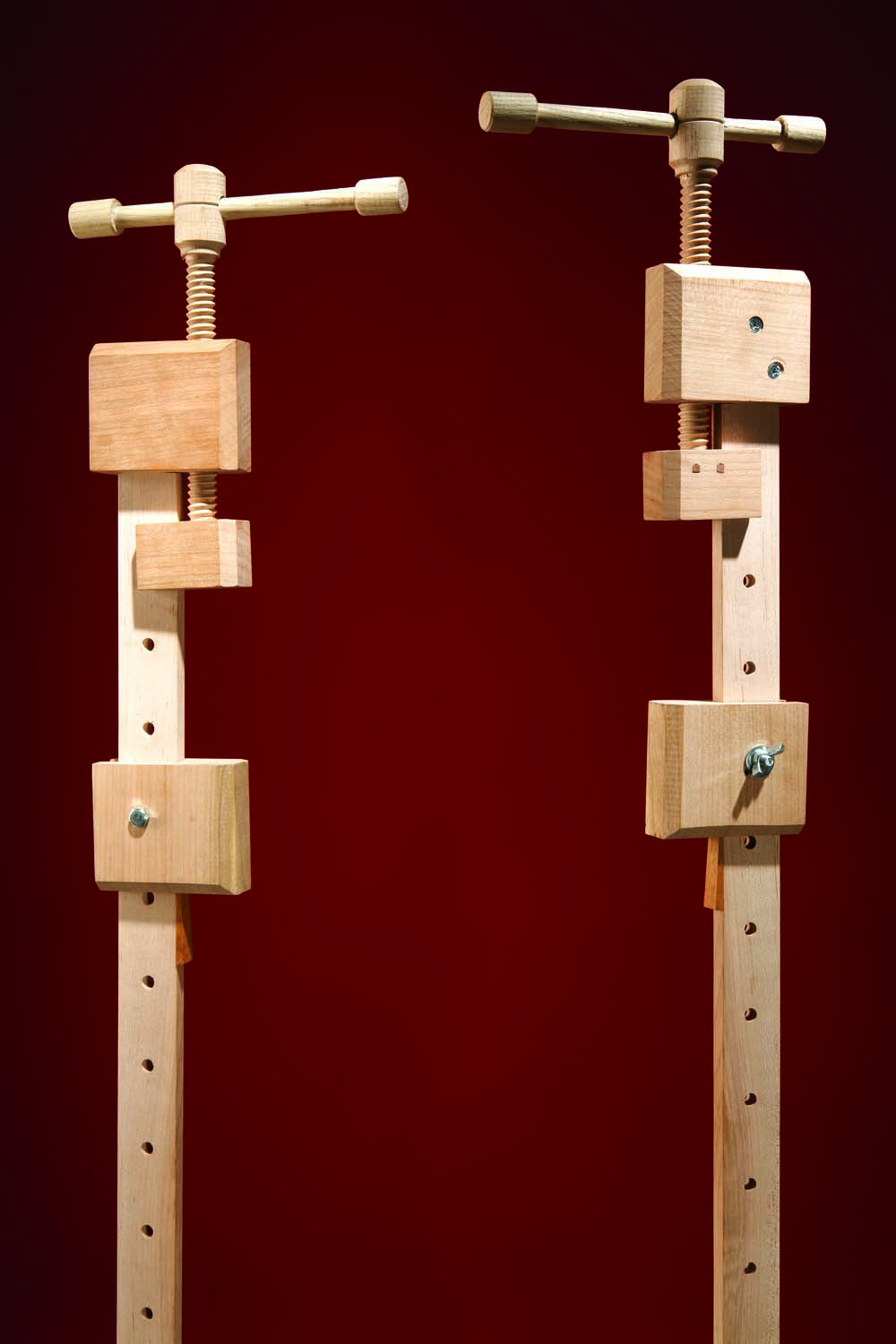
I saw stars the last time I dropped a bar clamp on my foot. Then I saw the light, in the form of a wooden handscrew. I’d been making my own handscrews—wood threads and all—for years. Why not apply the same method to bar clamps? By using wood, I could make bar clamps that would function as well as that wretched steel toe masher, but weigh much less and look much better. I could make them in multiples for next to nothing, because I had a ready supply of scrap stock (dense hardwoods such as hard maple, walnut and cherry are best) and a 3/4″ woodthreading kit (about $50—make two bar clamps and it’s virtually paid for). The only hardware to purchase would be a handful of 2-1/2″ 1/4-20 hex-head bolts and matching wingnuts.
Make the Clamp Bars
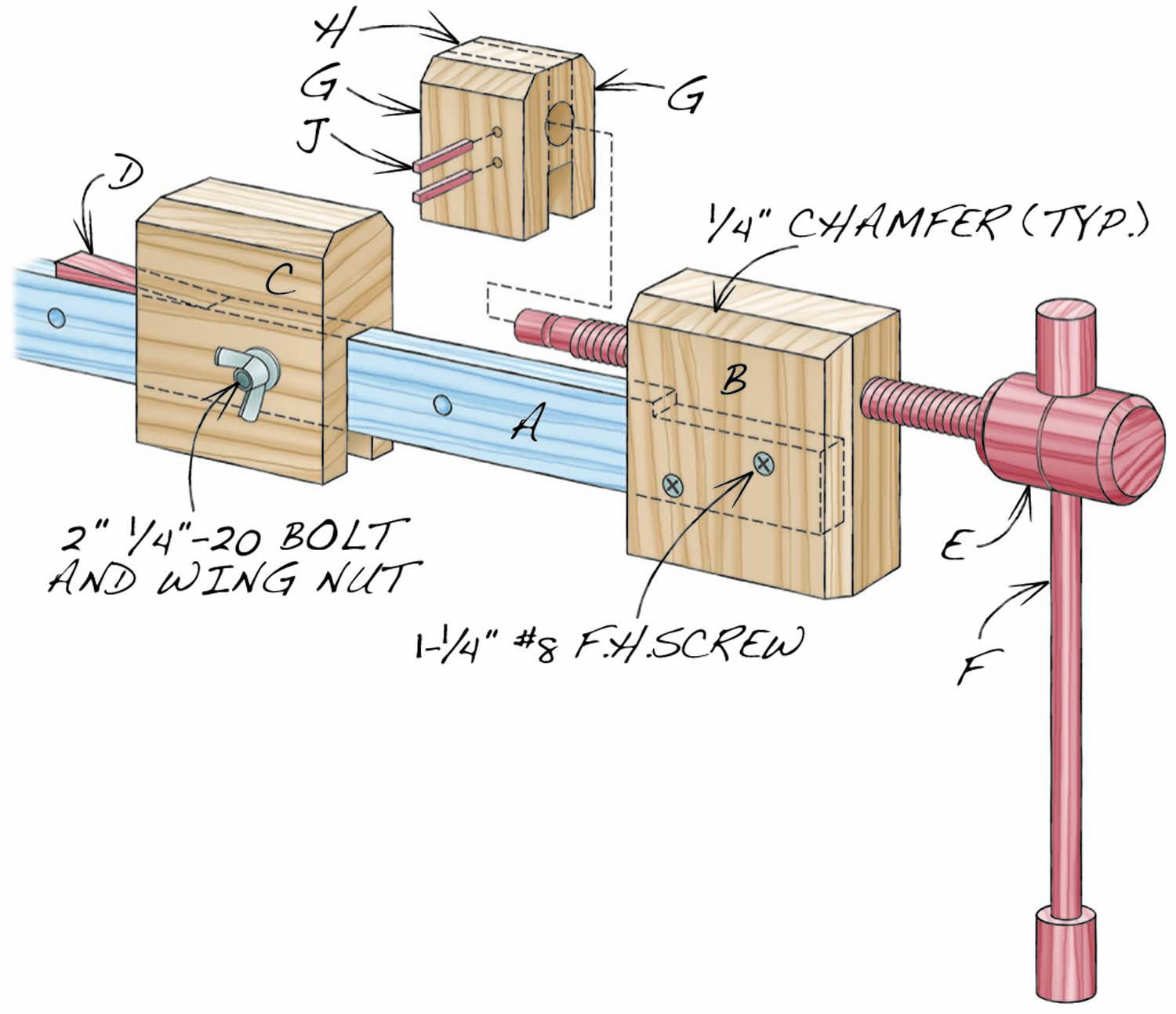
Fig. A. Exploded View
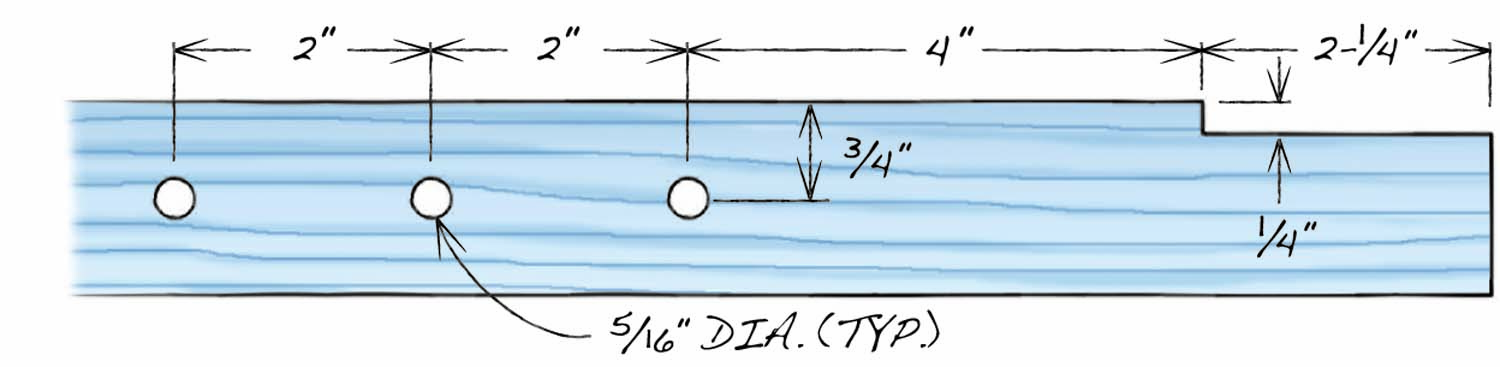
Fig. B. Bar
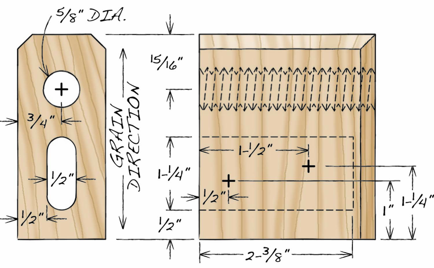
Fig. C. Head Block
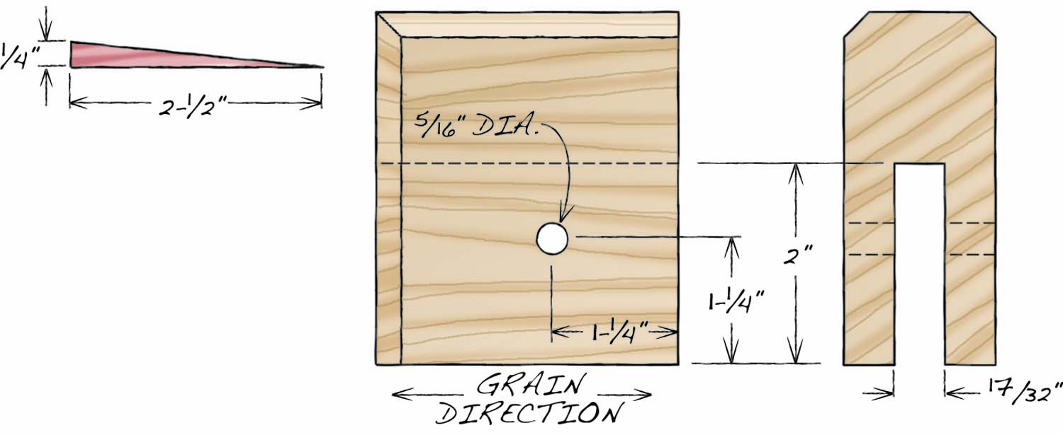
Fig. D. Rear Jaw
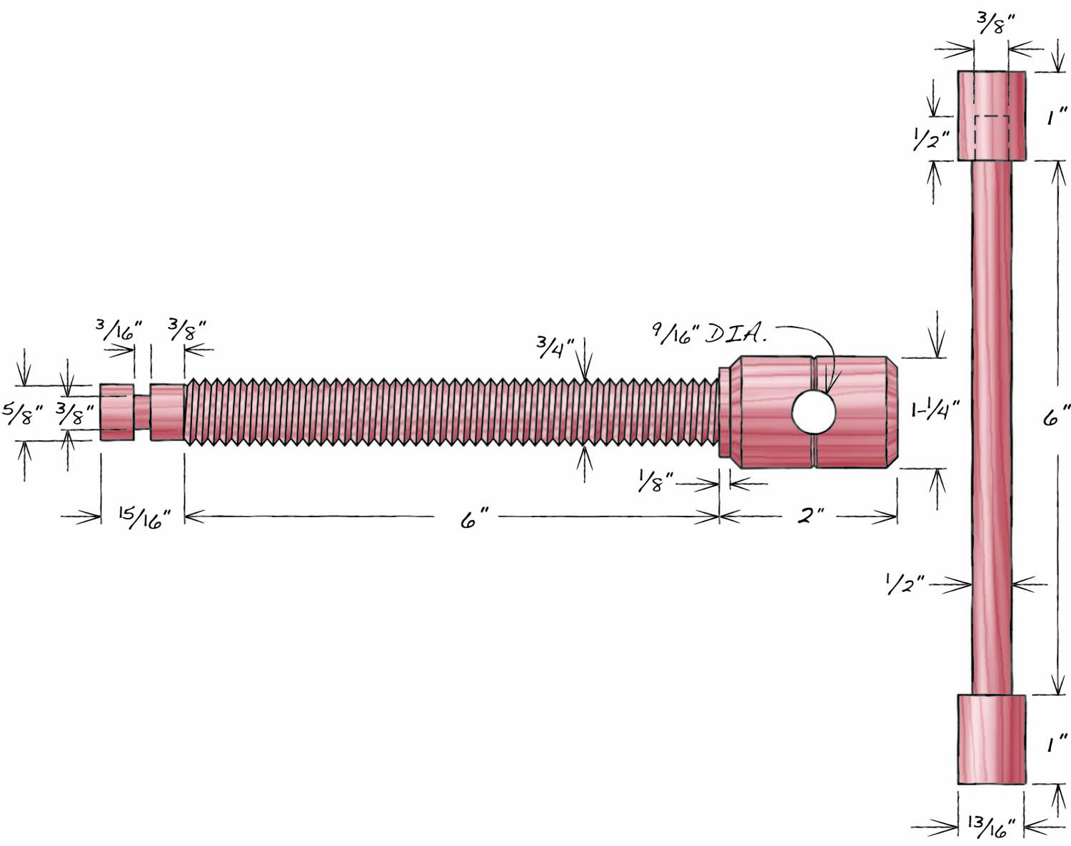
Fig. E. Wooden Screw and Handle
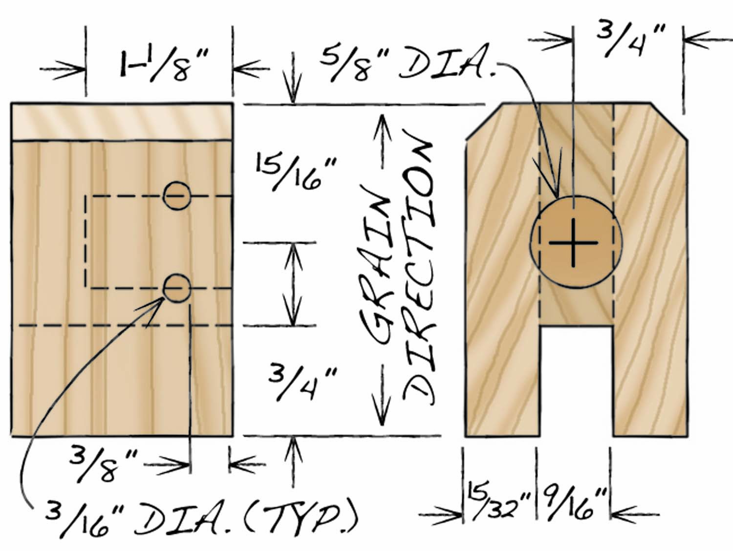
Fig. F. Sliding Jaw
Cutting Lists
|
Bar Clamp Overall Dimensions: 1-1/2″ Th x 3-1/2″ W x 18″ to 56″ L |
||||
|
Part |
Name |
Qty |
Material |
Th x W x L |
|
A |
Bar |
1 |
Hard maple (a) |
1/2″ x 1-1/2″ x 24″ to 48″ (c) |
|
B |
Head Block |
1 |
Cherry (b) |
1-1/2″ x 3″ x 3-1/2″ (d) |
|
C |
Rear Jaw |
1 |
Cherry (a) |
1/1’2″ x 3″ x 3-1/2″ (e) |
|
D |
Wedge |
1 |
Cherry |
1/4″ x 1/2″ x 2-1/2″ (e) |
|
E |
Screw |
1 |
Hard maple |
1-1/4″ dia. x 9-13/16″ |
|
F |
Handle |
1 |
Hard maple |
3/4″ dia. x 8″ |
|
G |
Sliding jaw ends |
2 |
Cherry (b) |
15/32″ x 1-1/2″ x 1-1/2″ (b, d, f) |
|
H |
Sliding jaw center |
1 |
Cherry (b) |
9/16″ x 1-1/2″ x 2-1/4″ [b, d, f) |
|
J |
Pin |
2 |
Cherry |
3/16″ x 3/16″ x 1-1/4″ |
|
Notes (a) Rift-sawn or quarter-sawn stock. (b) Quarter-sawn stock. (c) The bar can be any length. (d) Orient the grain to run vertically. (e) Orient the grain to run horizontally. (e) Tapers from 1/4″ to a point. (f) The completed sliding jaw measures 1-1/2″ x 1-1/2″ x 2-1/4″. |
||||
You can make the bars (A, Fig. A, Fig. B) just about any length, but I typically make only two sizes: 24″ and 48″ (these sizes produce clamping capacities of 16″ and 40″). When I need a longer clamp, I just fasten two clamps together end-to-end, using hex-head bolts and the holes drilled in the bars.
Photo 1. Create stable clamp bar stock by ripping blanks from the edge of a thick plain-sawn board. This method creates rift- and quarter-sawn stock that’s less likely to cup or bow than plain-sawn stock.
Flat-sawn bars may cup or bow. (On flat-sawn boards the annual rings that appear on the end grain are tangent to the face.) Rift-sawn bars, in which the annual rings run at a steep angle (greater than 45°) to the face, are more stable and quarter-sawn bars, in which the annual rings are perpendicular to the face, are the most stable. To harvest rift- and even quarter-sawn bars from flat-sawn stock, rip 5/8″ wide blanks from the edge of a board milled to 1-1/2″ thickness (Photo 1). After ripping, run the blanks through the planer to remove the saw marks and end up with bar stock that’s 1/2″ thick and 1-1/2″ wide.
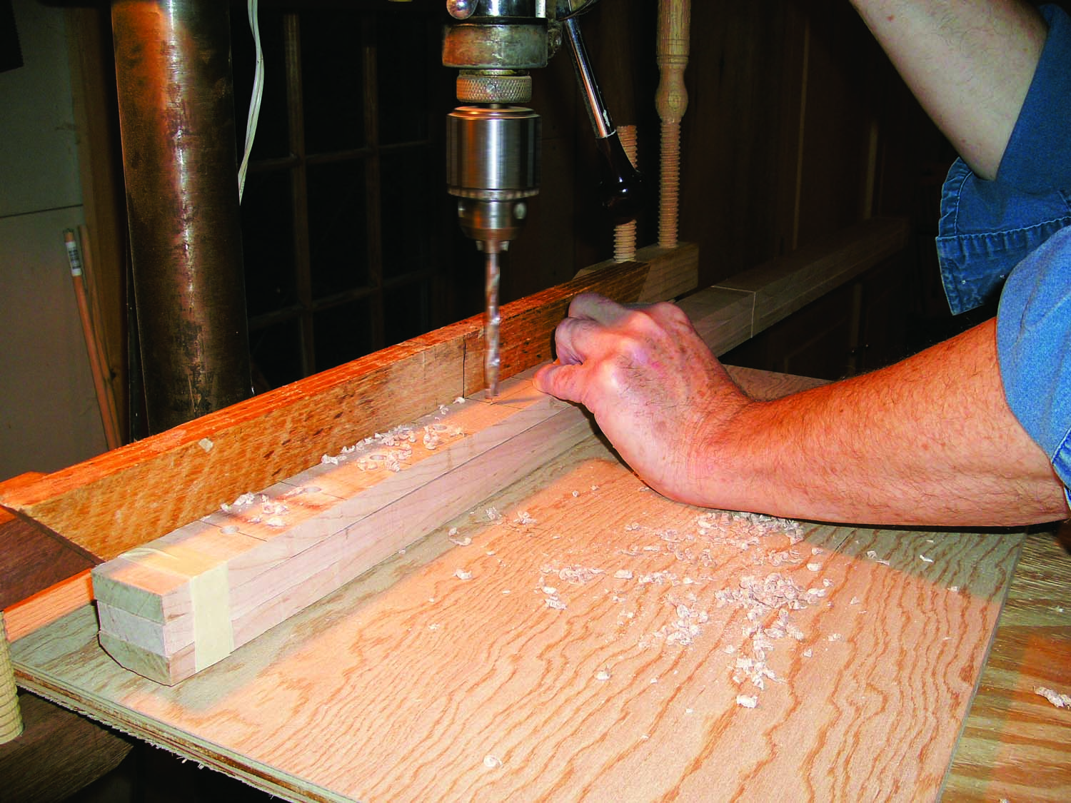
Photo 2. Drill centered and evenly spaced holes through each bar blank. Tape several blanks together and you’ll only have to mark the holes on the top one.
Use a drill press with a fence and a brad point bit to drill centered 5/16″ dia. holes down the length of each bar (Photo 2). Start 6-1/4″ from one end and space the holes 2″ apart. Complete the bar by bandsawing a notch on one end to create a single-shouldered tenon. First, use a miter gauge to cut the tenon’s 1/4″ shoulder in the bar’s top edge, 2-1/4″ from its “front” end. Then turn the bar and make a rip cut to complete the notch (Photo 3).
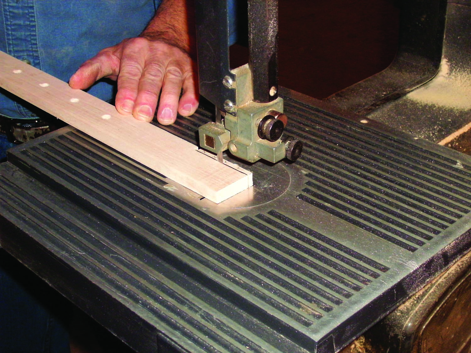
Photo 3. Cut a notch on one end of each bar to create a single-shouldered tenon that will be used to mount the bar in the clamp’s threaded block.
Make the Threaded Block
Orient the grain vertically on the head block (B; Fig. C). To make this block, start by milling a quarter-sawn blank flat and square to 1-1/2″ x 3″. It’s important to use quarter-sawn stock for this block because a screw tap cuts cleanest when it cuts straight through the wood’s growth rings. Holes tapped through the rings at other angles may result in chipped or splintery threads. In most cases, these crumbly threads will still work, but when you’re torquing on the screw to tighten the clamp, you don’t want the threads to fail.
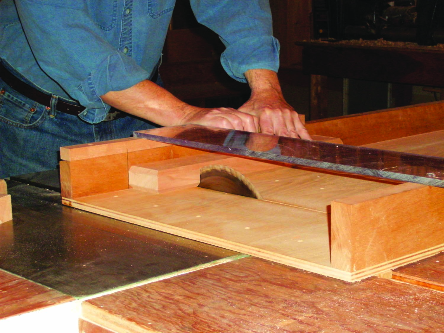
Photo 4. Photo 4 Crosscut a head block for each clamp from a quarter-sawn blank that’s been chamfered on top. Chamfer the end of the blank before cutting each block.
Install a fence on the router table to chamfer the top of the blank and use a miter gauge or a sled to chamfer one end. Then cut the blank into 3-1/2″ long blocks—marking the crosscut sled’s fence makes this easy work (Photo 4). After cutting each block, return to the router table and chamfer the end of the blank.
Mark the center of the threaded hole and both ends of the 1-1/4″ long mortise on the non-chamfered edge of each block. Then use a square and pencil to strike layout lines across the edge at these three points.
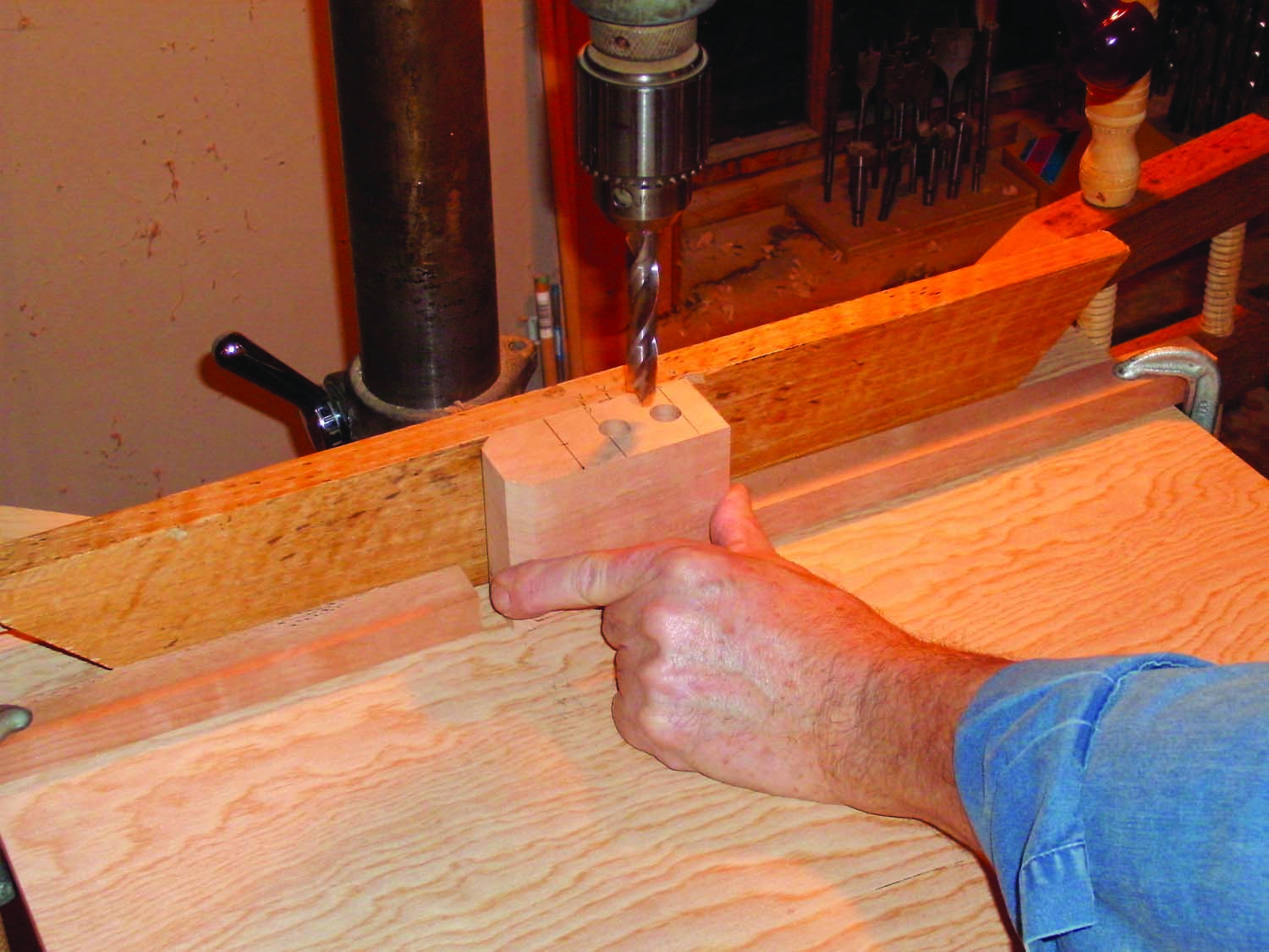
Photo 5. Drill centered, stopped holes in each head block to create a mortise for the bar. Establish the ends first, using clamped-on stops locate the bit. Then drill out the center.
Install a 1/2″ dia. brad point bit in the drill press and set the fence to center the bit on the block’s edge. Install stops and set the drilling depth at 2-3/8″. Then drill the mortise (Photo 5). Pare the mortise shoulders flat with a chisel, but leave the ends rounded.
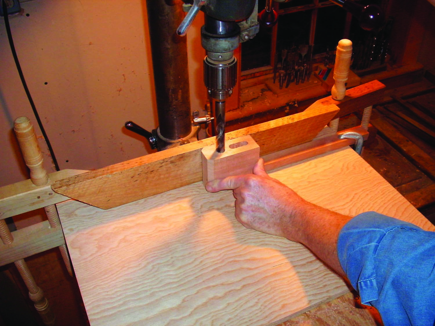
Photo 6. Drill a centered hole through each head block for the screw. Drill until the bit’s point barely pokes through the bottom. Then turn the block around to finish drilling the hole.
Use a 5/8″ dia. brad point bit to drill the hole that will be threaded (Photo 6). Set the depth stop to barely allow the bit’s center spur to exit the opposite end of the block. Align the bit with the center point marked earlier and drill to the depth stop. Then turn the block around, keeping the same face against the fence, align the bit with the exit hole and drill out the last bit of waste. This two-step approach keeps the bit from blowing out the end of the block. Securely clamp each block chamfered-edge up in the face vise. Then use a 3/4″ dia. screw tap to thread the hole (Photo 7). Cut the threads by repeatedly turning the tap about 180° and then reversing directions to clear the waste.
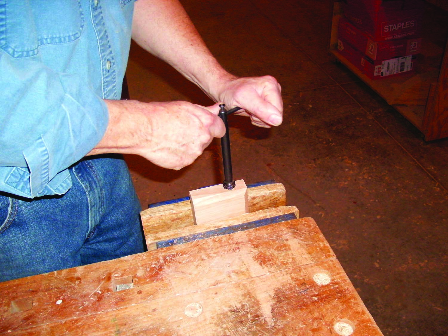
Photo 7. Thread the hole using a tap. Start on the back of the block and work all the way through. Then remove the T-handle and let the tap fall into your hand below.
Assemble the Bar and Threaded Block
Use a chisel to pare the corners of the bar’s tenon into a shape that will fit the mortise in the threaded block. Then spread glue inside the mortise and drive the head block onto the tenon, using the tenon’s top shoulder to register the block (Photo 8). Check the fit with a square and adjust, as necessary. Then drill two countersunk pilot holes install 1-1/4″ #8 screws to reinforce the joint.

Photo 8. Drive each completed head block onto the bar after paring the corners of the bar’s tenon to fit the block’s rounded mortise.
Make the Rear Jaw
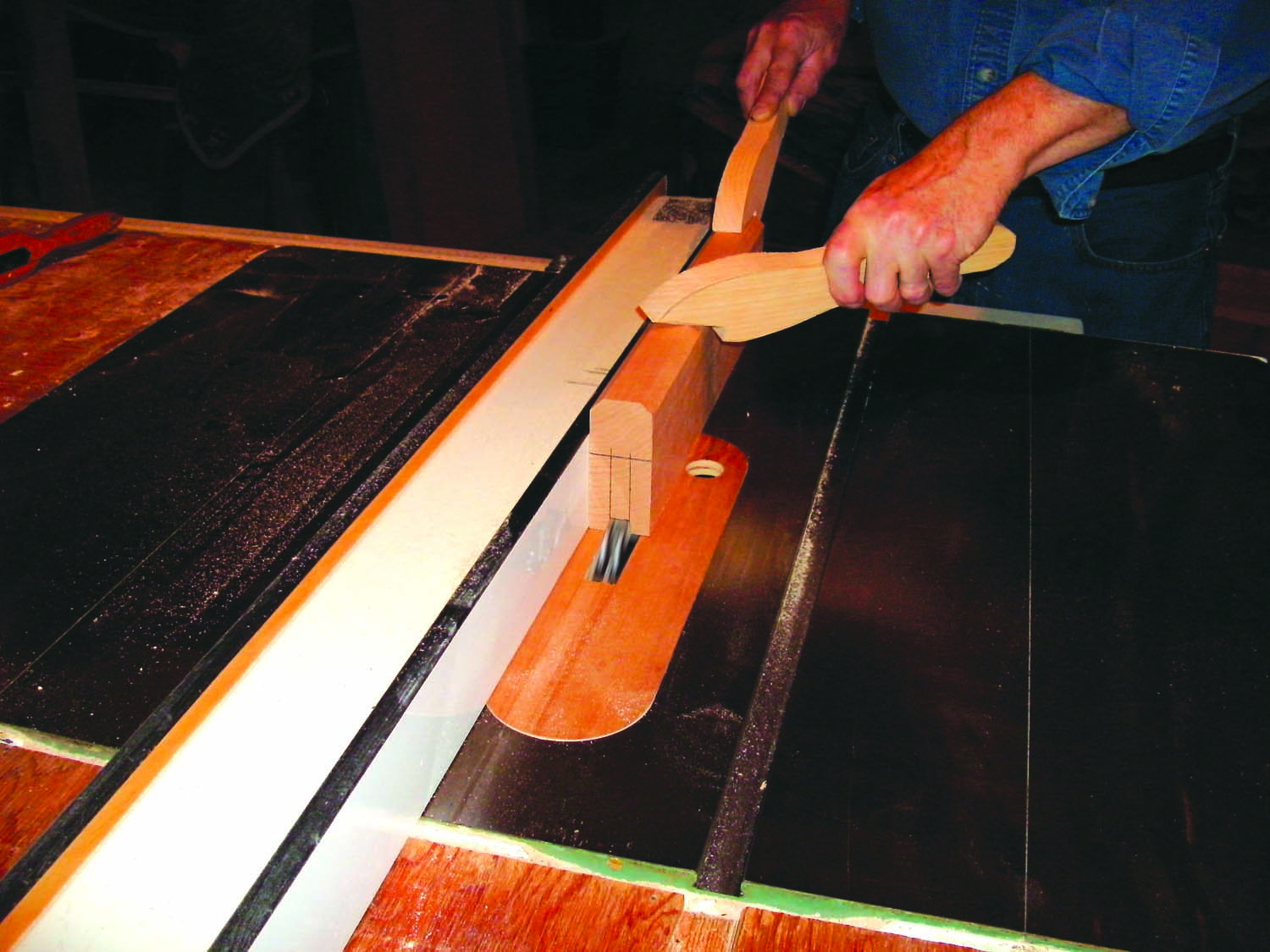
Photo 9. Cut a deep centered groove in the rear jaw blank by making multiple passes and incrementally raising the dado blade.
Start by milling a length of 1-1/2″ x 3-1/2″ stock flat and square. You can use rift-sawn stock or quarter-sawn, as for the threaded block, but for this rear jaw (C; Fig. D), the grain’s orientation isn’t as important. Chamfer the top edge of the blank and one end. Then cut a 1/2″ wide x 2″ deep centered groove in the bottom (Photo 9). To facilitate installing and removing the jaw, install one or more paper shims (as necessary) between the dado cutters to make the dado ever so slightly wider than the bar. Cut the blank into 3″ long sections to create the jaws. Chamfer the end of the blank before cutting each jaw.
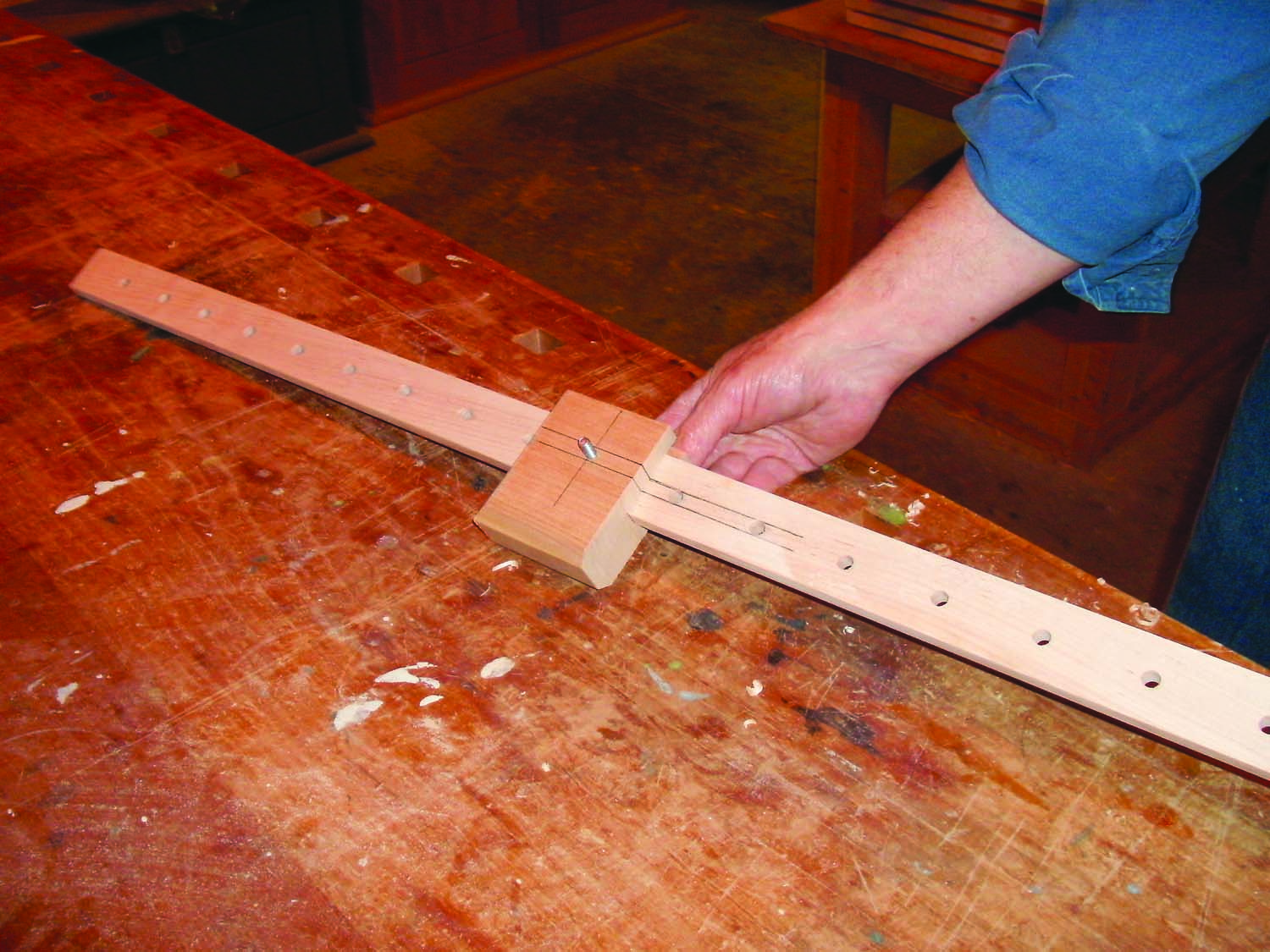
Photo 10. Test fit the rear jaw on the bar to make sure it slides freely and the hole drilled through it aligns with the holes on the bar.
Lay out the location of the hole used to fasten the jaw to the bar. Set up the drill press and drill a 5/16″ dia. hole through one jaw. Slide this jaw onto one of the bars and install a 1/4-20 hex to make sure the holes align properly (Photo 10). The top edge of the bar should rest against the jaw’s groove. Make a wedge (D) to install between the bar and the groove to keep the jaw from rocking back when clamping pressure is applied.
Make the Screw and Handle
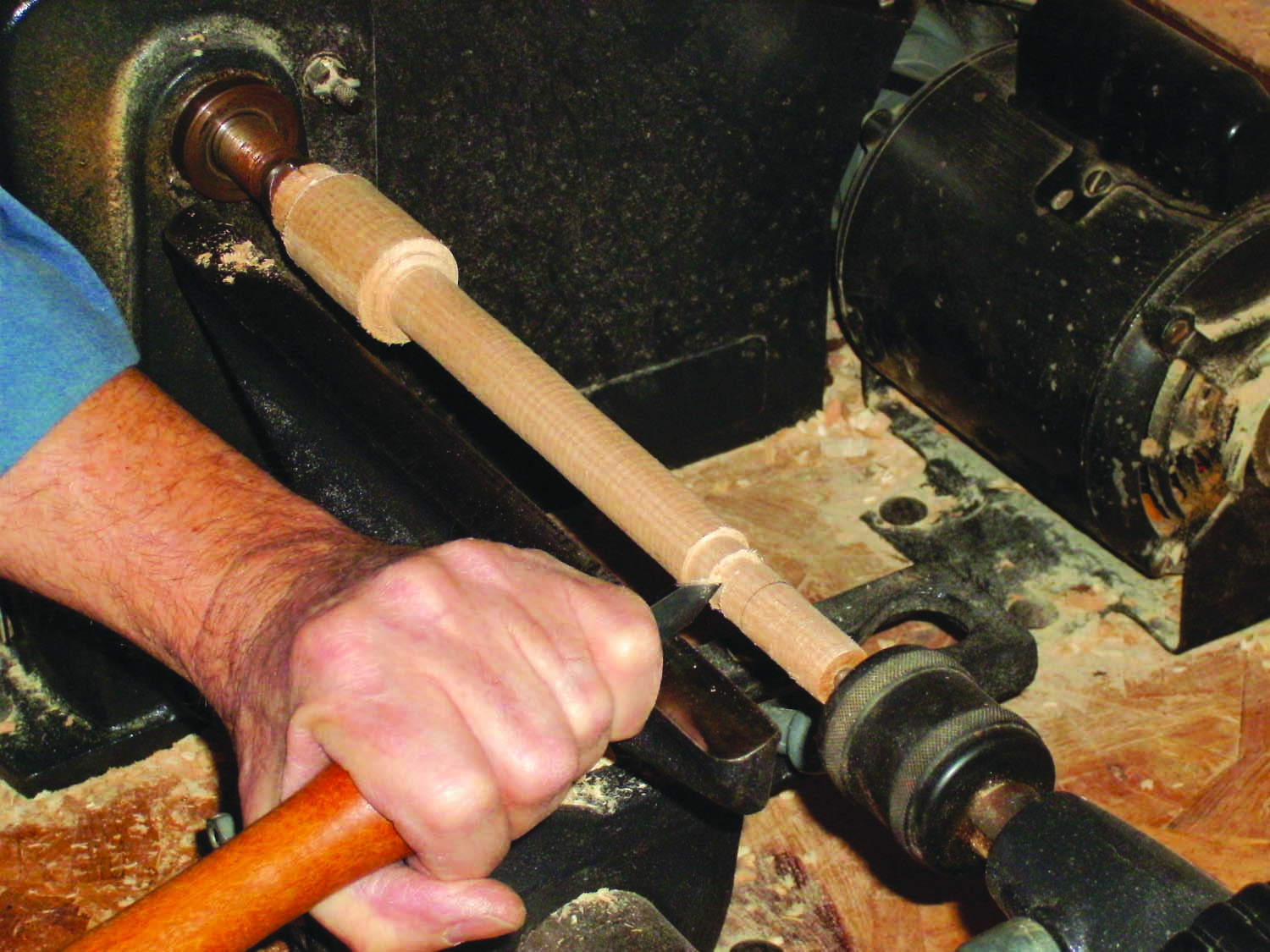
Photo 11. Rough out each screw by turning cylinders for its head, shaft and tenon. Turn a groove in the tenon to house the pins that will hold the screw in the sliding jaw.
Turn the screw (E; Fig. E) from a 1-1/2″ x 1-1/2″ x 11″ blank (Photo 11). Use a gouge to turn the blank to a cylinder and a parting tool and calipers to establish the locations and diameters of the screw’s head, shaft and tenon. Use the gouge to turn these three cylinders and the parting tool to detail the head and cut the groove in the tenon. Remove the turned blank from the lathe and cut the screw free using a handsaw. Then head to the drill press to drill the hole for the handle through the screw’s head. Support the head in a V-block to accurately drill this centered hole. Use a 3/4″ dia. thread box to complete the screw (Photo 12).
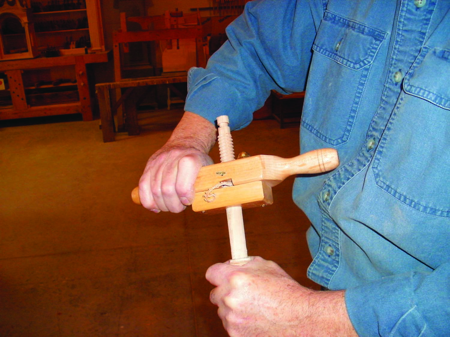
Photo 12. Cut threads on the screw’s shaft using a thread box.
Turn the handle (F) from a 1″ x 1″ x 10″ blank. Initially, make the 7/16″ dia. shaft between the end pommels 6-1/2″ long. Then turn a 3/8″ dia. x 1/2″ long tenon against one of the pommels. Finish-sand the handle, remove the blank and use a handsaw to free the handle. Then cut off the pommel that’s adjacent to the tenon and drill a 3/8″ dia. stopped hole in it to create a mortise for the tenon. Slide the handle through the hole in the head of the screw. Then spread glue in the mortise and reinstall the pommel. Clamp the joint and let it dry.
Make the Sliding Jaw
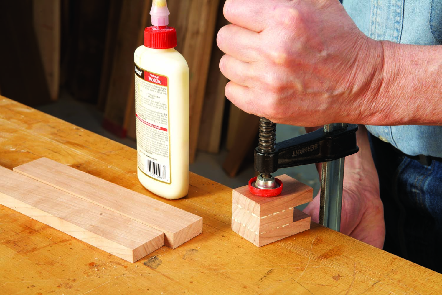
Photo 13. Make each sliding jaw by gluing together three rift-sawn pieces cut from a pair of long blanks. The shorter, thicker middle piece automatically creates the slot.
Like the head block, the sliding jaw (Fig. F) should be made from quarter-sawn stock and its grain is oriented vertically. This jaw is made differently, though, because it has to be slotted to fit over the clamp’s bar, and it’s too small to safely cut the slot using the tablesaw. The best way to make this jaw is by gluing together thin quarter-sawn pieces (G, H; Photo 13).
Start by harvesting a pair of 5/8″ thick x 1-1/2″ wide quarter-sawn blanks (at least 12″ long) from a flat-sawn board using the method shown earlier to create stock for the clamp’s bar. Mill one of these blanks to 9/16″ thickness and the other to 15/32″ thickness. Square one end of each blank and then cut 1-1/2″ long pieces from the 9/16″ blank and 2-1/4″ pieces from the 15/32″ blank. Make sure the faces remain flush when you glue the parts together.
The slot on this laminated jaw is slightly wider than the bar, so the jaw will slide freely.
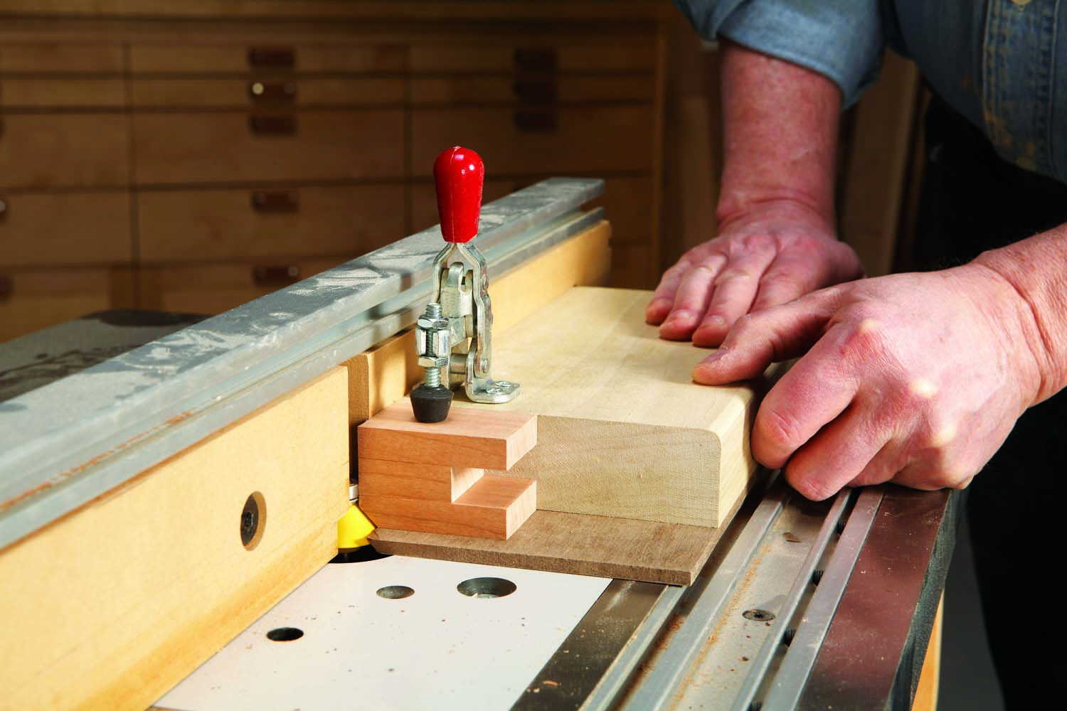
Photo 14. Use a sled to chamfer the sliding jaw’s top edge. This part is too short to rout using only the fence. Make the sled by gluing a squared block onto 1/4″ hardboard and attaching a toggle clamp.
Make a sled to chamfer the top edge of the sliding jaw (Photo 14). Complete the cut by making several passes. You can either slightly raise the bit between each pass or set the bit to its final height and then clamp the jaw in slightly closer to the fence between each pass.
Drill Holes for the Screw
Mark and drill the holes in the sliding jaw for the pins (H) that will capture the wooden screw. Start by drilling a 5/8″ dia. hole in the back face of the jaw to house the screw. Then locate two 3/16″ dia. holes in the side of the jaw for the pins. The idea is to seat the pins in line with the 3/16″ wide groove in the screw’s tenon.
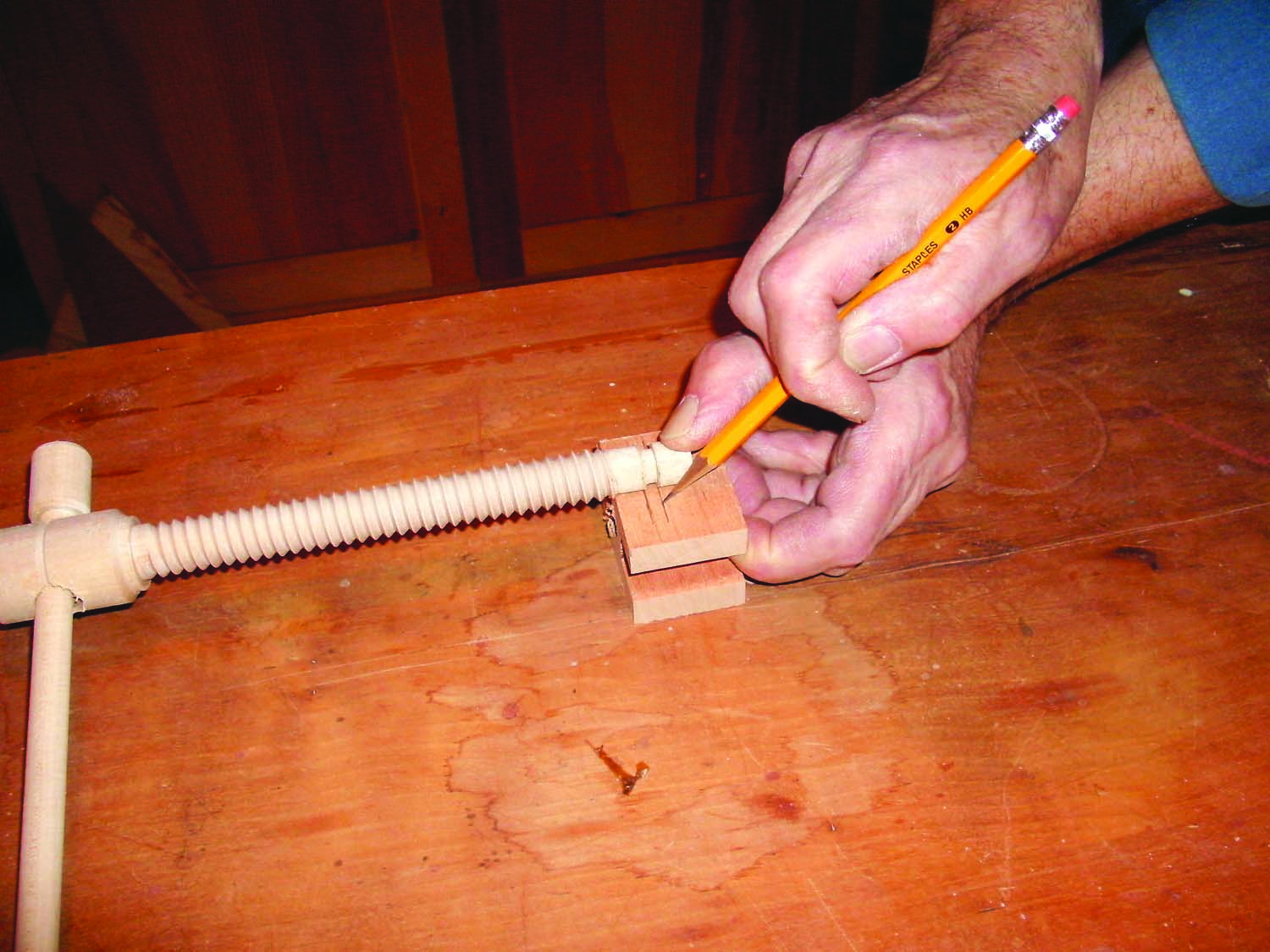
Photo 15. Hold the screw’s bottom thread against the sliding jaw’s back face to transfer the location of the groove’s shoulders. The location may vary, so mark each screw and jaw separately.
First, precisely mark the shoulders of the screw’s groove on the side of the jaw (Photo 15). Then use a square to mark the top and bottom edges of the 5/8″ dia. hole you’ve drilled in the block’s face—these lines will intersect the groove’s shoulder lines. Drill the holes for the pins, centered between the groove’s shoulder lines and centered on the hole’s edge lines (Photo 16). Drill these holes deep enough to pass through the 5/8″ dia. hole, but not through the entire block.
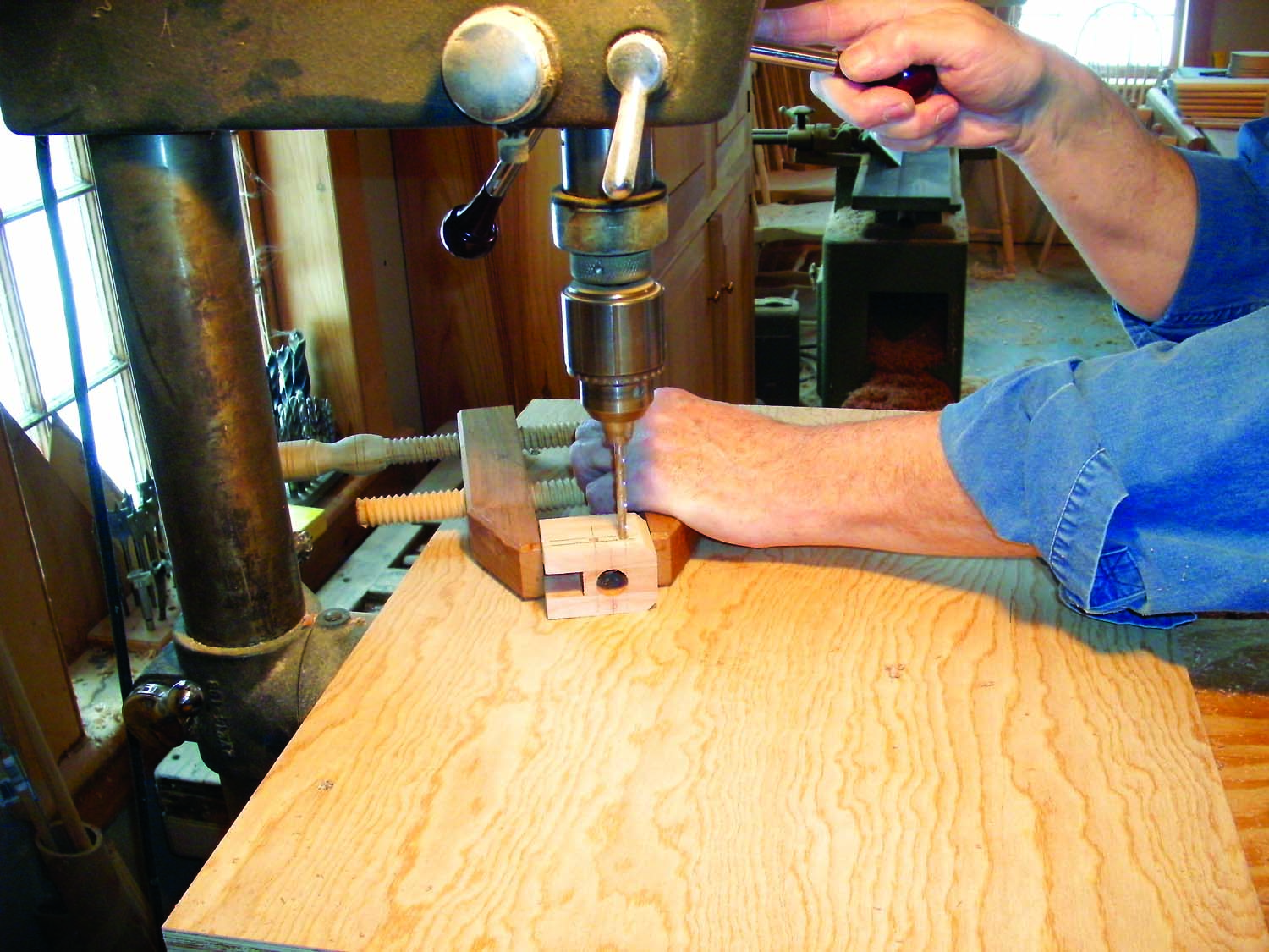
Photo 16. Drill holes in the sliding jaw for the pins that will capture the screw. Center the holes between the groove shoulder lines and on lines marking the edges of the jaw’s stopped hole.
Assemble the Clamp
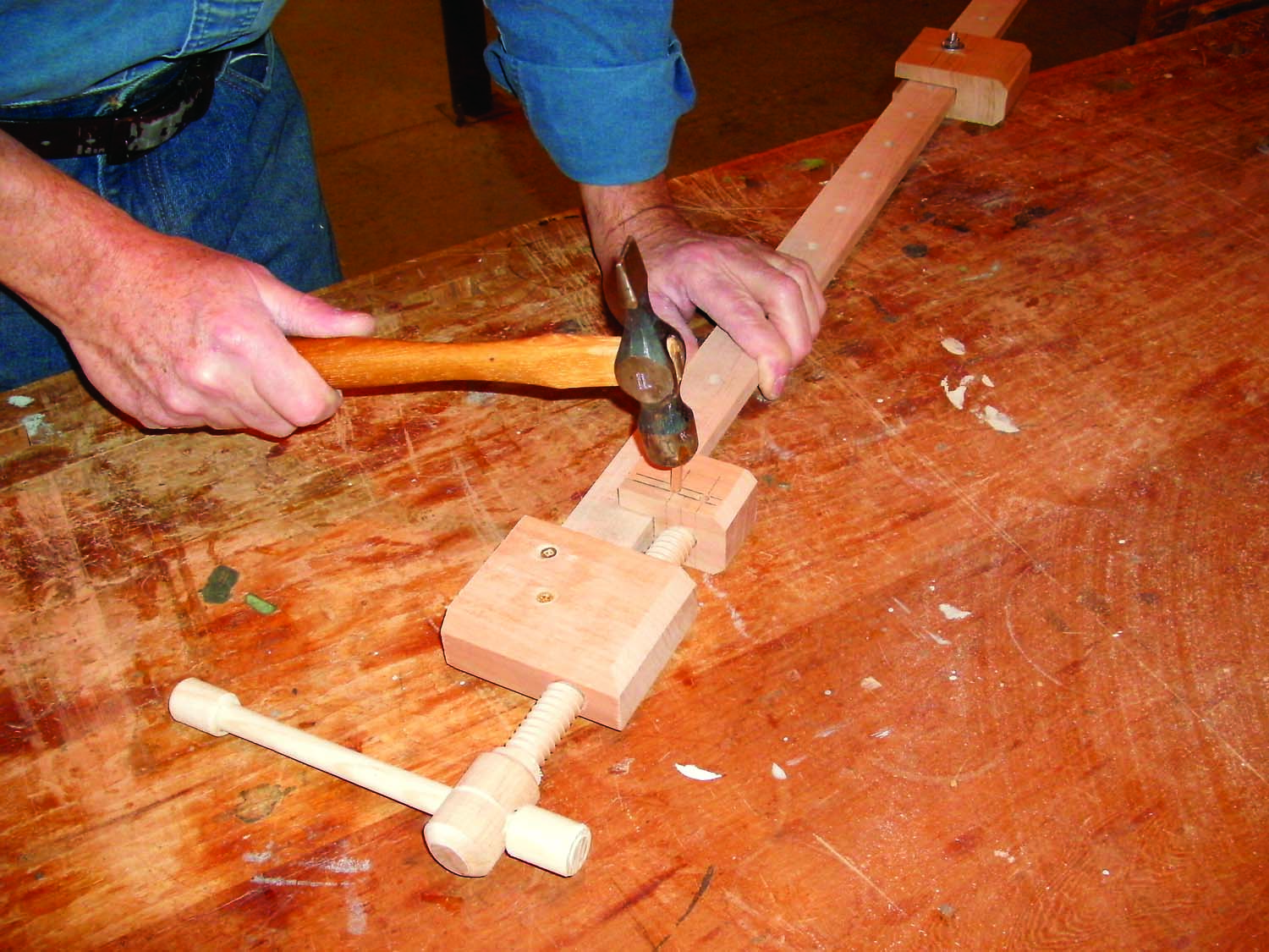
Photo 17. Capture the screw in the sliding jaw by driving square pins into the holes so they track inside the groove.
Thread the assembled wooden screw through the threaded block that’s mounted on the clamp bar. Seat the screw’s tenon in the hole in the back face of the sliding jaw. Hold the screw tight against the jaw to align its groove with the pin holes. Then drive in the two 3/16″ square pins (Photo 17). Work the screw as necessary to wear in the pins and grooves, until it threads easily in both directions. Fasten the rear jaw to the clamp bar using a 1/4-20 hex head bolt.
Here are some supplies and tools we find essential in our everyday work around the shop. We may receive a commission from sales referred by our links; however, we have carefully selected these products for their usefulness and quality.


