We may receive a commission when you use our affiliate links. However, this does not impact our recommendations.
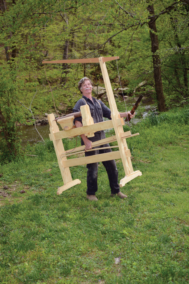
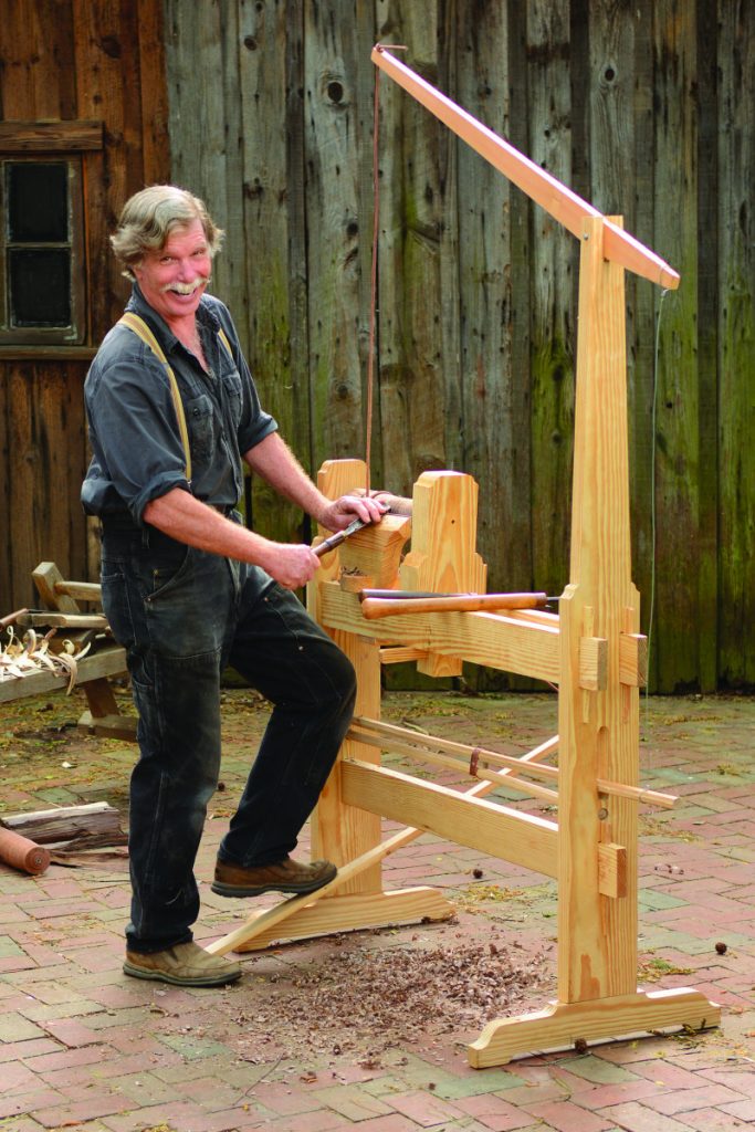
Can a portable, foot-powered lathe make a believer out of you?
Wood turning on a spring pole lathe is all about reciprocation, all about back and forth. For example:
Q: “Don’t you get tired of standing on one leg?”
A: “Sure, but if you try to work the treadle with both legs – you fall over.”
or:
Q: “Bet you can’t wait for electricity!”
A: “Well, this is an alcohol-powered lathe!” (Said while taking a drink from your big colonial mug.)
or:
Q: “That’s a lot safer than a power lathe.”
A: “Unless you lean forward too far!” (Said while tilting your head into the path of the descending spring pole.)
But snappy comebacks won’t win anyone over to your side of the spring pole lathe. The response that does win a true believer is this: “Here, give it a try!” (Said while passing the turning gouge into the questioner’s hands.)
Adapted from an old German technical encyclopedia, this lathe is precise, portable, powerful, adjustable, adaptable and self-contained. The two dead centers permit no play in the workpiece, and the direct drive of the cord wrapped around the wood loses no power in transmission, friction or vibration. The great virtue of this particular lathe is that it uses two wooden springs, linked by a sliding collar, to make the tension instantly adjustable. The overhead rocker arm lengthens the throw of the springs and puts the drive cord right where you need it.
Equally important in this design, however, aside from how rewarding the lathe is to make and use, is how accessible the materials are. I based the entire design on readily available pine construction timber and you can just about build the entire lathe from a single 12′-long 2×12 ripped down to the actual 4″ and 7″ widths required.
Form the Frame
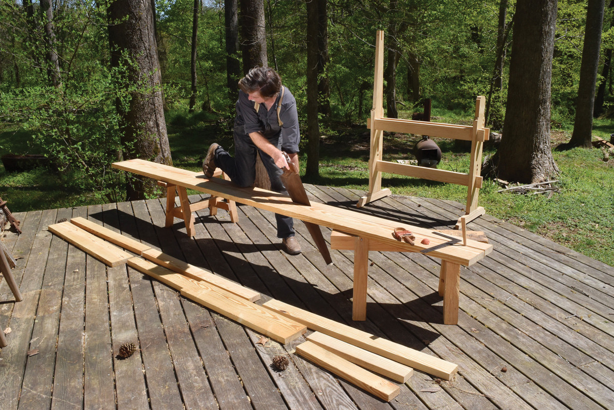
Almost there! A single 12′ plank of nominal 2×12 will give you most of the wood you need.
Start with the three horizontal rails, choosing the two best-matched for the top pair (the “ways”) of the lathe. Keep the parts in order by marking them with triangles.
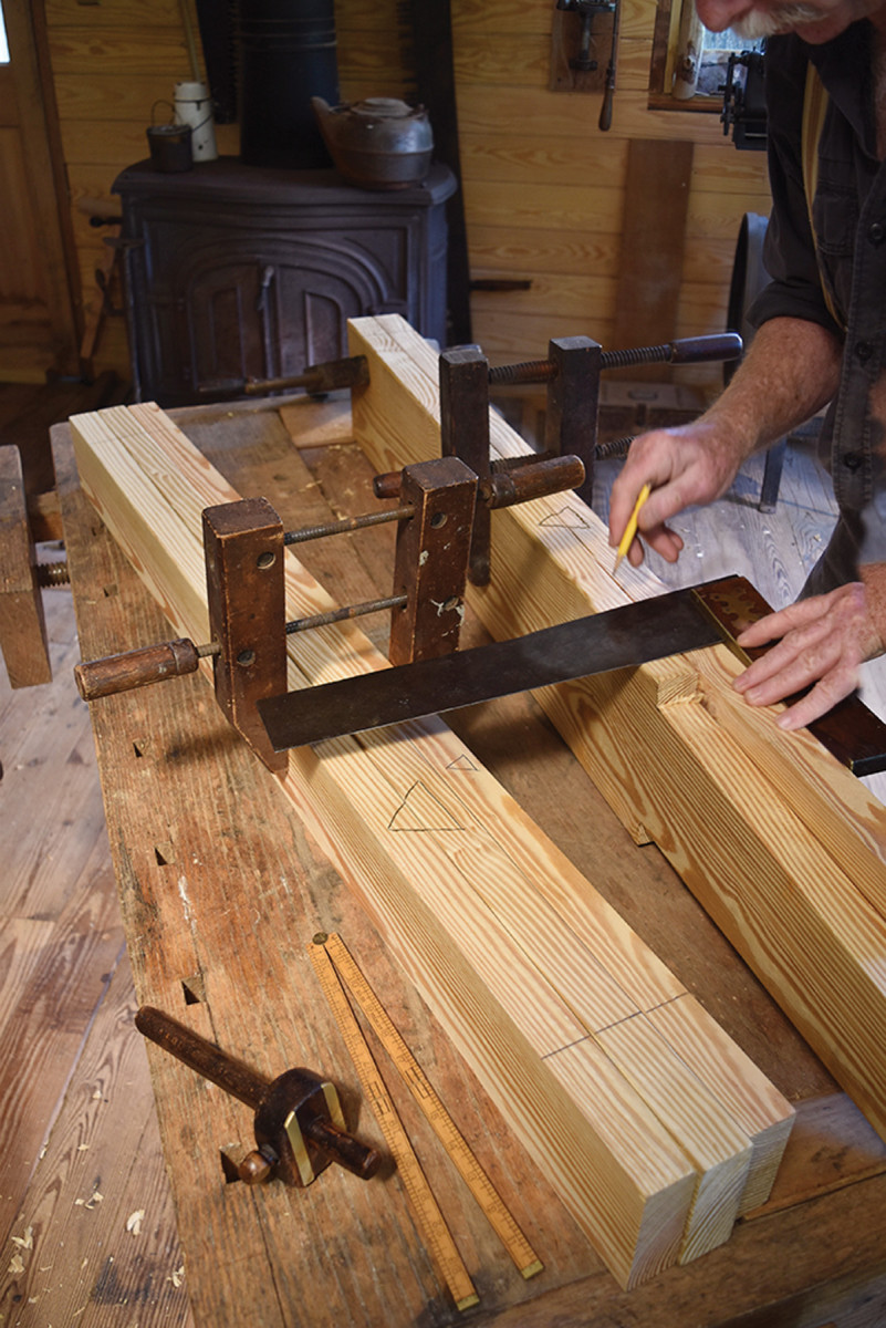
Matched marks. As with any frame construction, start by ganging up all the horizontal (or vertical) members and setting out the lines across them while they are clamped together.
Set the top pair together on the benchtop, narrow edges up, and pencil a triangle, pointing to the front (to you) overlapping the two top rails. The bottom rail gets a single triangle on its upper edge, again pointing to the front of the lathe.
These 4′-long rails can be slightly uneven in overall length; the important thing is laying out an equal span between their tenon shoulders. Strike your shoulder lines across the three rails at least 4″ from the ends to leave enough strength in the protruding tenons for the wedges that draw them tight.
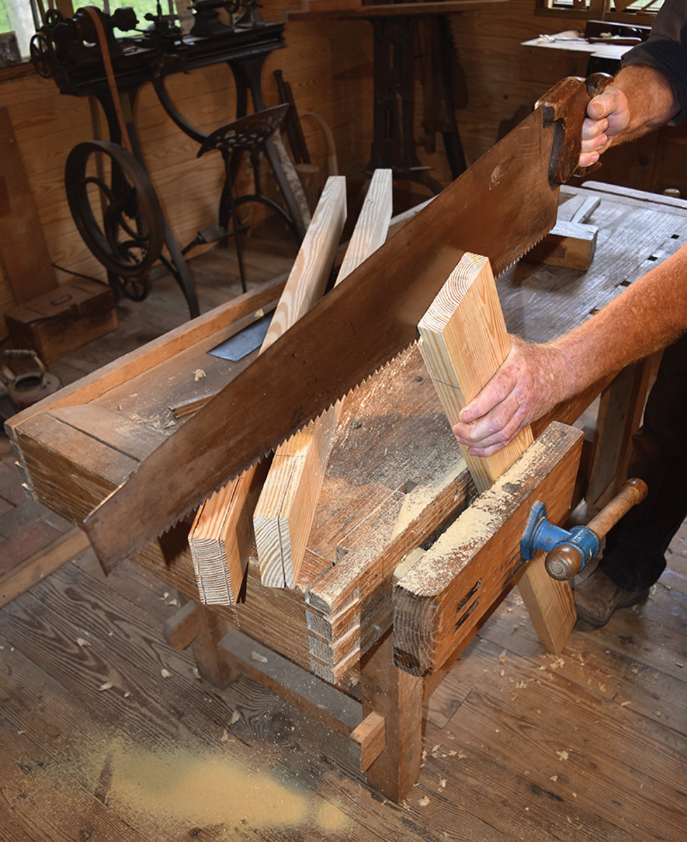
Rip it good. I rip the long-grain cheeks of the tenons before crosscutting the shoulders. This cuts down on the trimming needed to clean up a split caused by a wobble of the mighty rip saw.
Now scribe the thickness of the tenons on the top rails (1″) with the marking gauge held against what will become the inner faces. These are single-shouldered tenons on the two top rails, with the shoulders turned outward – to the front and back of the lathe. Single-shouldered tenons are less stable than a two-shouldered version, but, because they are set in opposing pairs on the two rails, they cancel out each other’s tendency to twist the mortised post. Without a mate to counter it, the lonely lower rail is best cut with a standard, two-shouldered tenon.
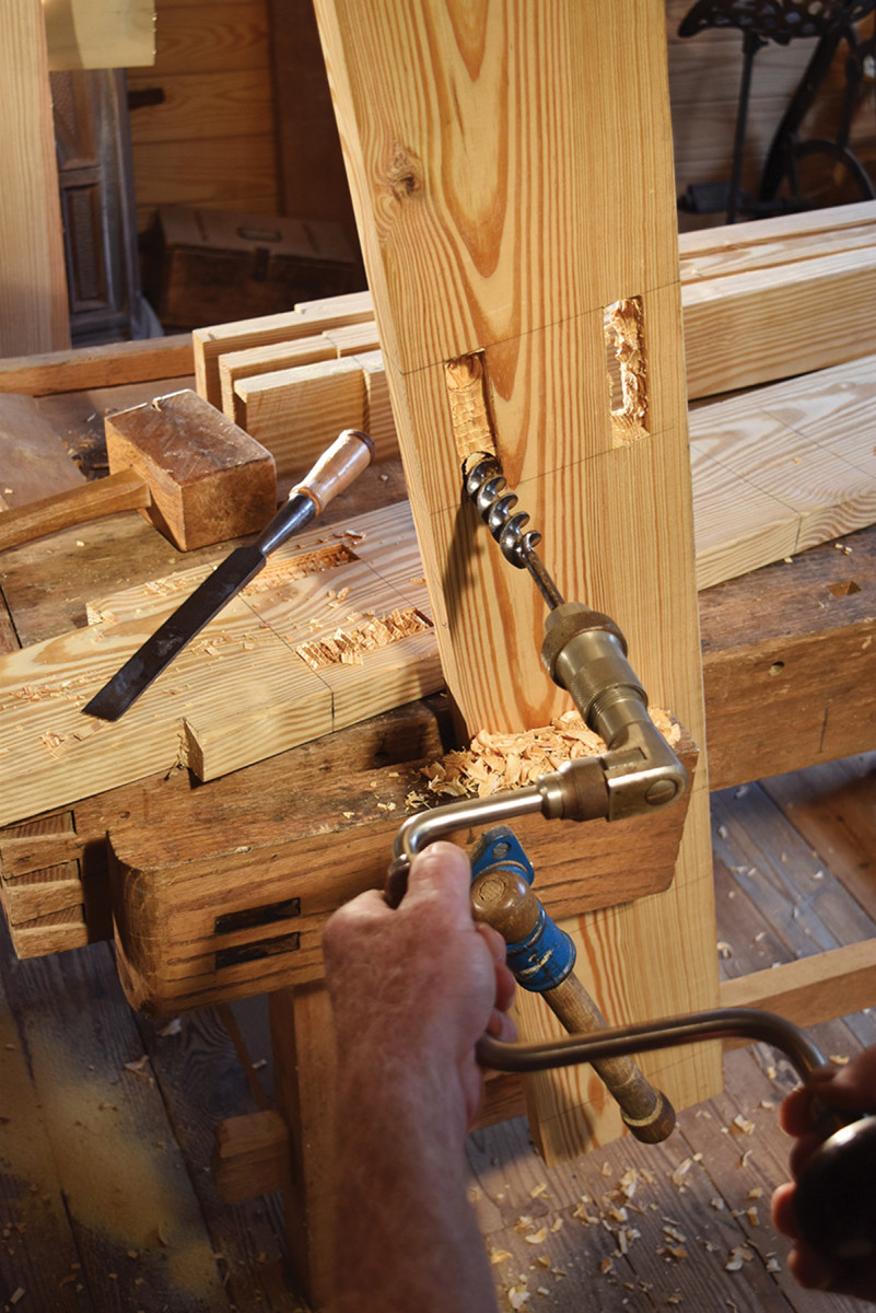
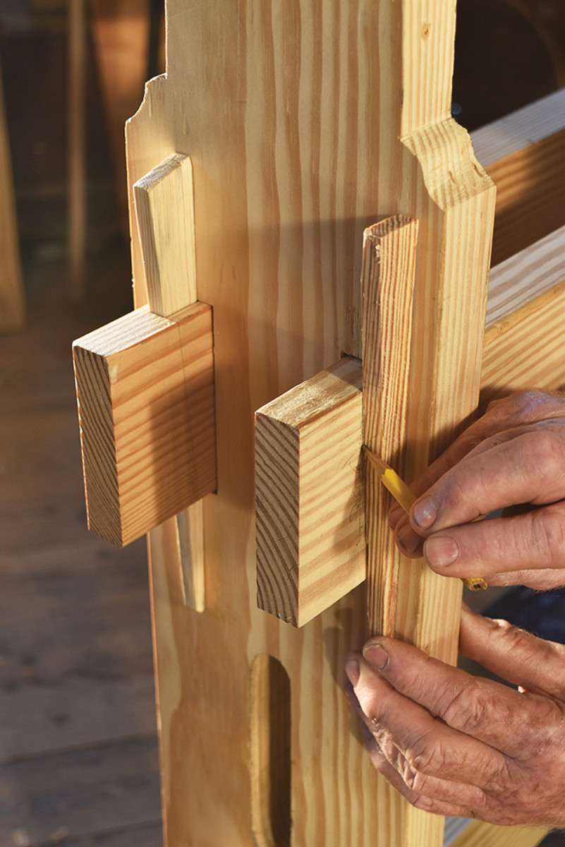
Bore & more. Trenching in both faces of the mortises through the posts will help guide the boring and chiseling that follow.
In the same manner as earlier, lay out the height of the mortises in the two posts and the shoulders of their tenons for the feet. Again, mark their front edges with the overlapping triangle. With the gauge working consistently from the triangle-marked edges, scribe the 1″ widths of the mortises through the posts. Mark each setting of the gauge on both faces of both posts before you readjust the gauge to mark the next line.
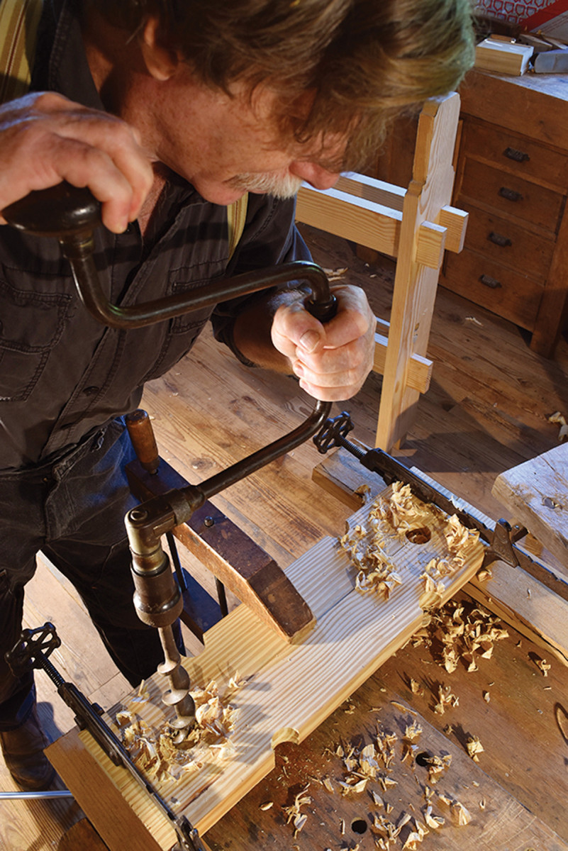
These mortises are simply rectangular tunnels quickly excavated after making careful, clean entrances on the opposite faces. Chop these tunnel entrances with repeated cross-grain chisel cuts, leaving 1⁄4“-deep trenches to register the positions of the auger and chisel work that follow. Fit the lips of the auger into this trench and bore halfway through from both sides, meeting in the middle. Clean up with the firmer chisel.
You now have your first chance to stand up the frame of the lathe and to see what fun it is fitting six mortise-and-tenon joints together at the same time. Call me when you’re done.
Spring Pole Lathe Cut List
No.ItemDimensions (inches)MaterialComments
t w l
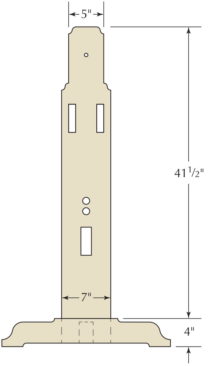
❏ 1 Short post 11⁄2 7 45 Pine 31⁄2” double tenons
❏ 1 Long post 11⁄2 7 66 Pine 31⁄2” double tenons
❏ 2 Feet 11⁄2424Pine
❏ 1 Bottom rail 11⁄2 4 48 Pine 1″-thick TBE*
❏ 2 Top rails 11⁄2 4 48 Pine 1″-thick TBE*
❏ 1 Rocker arm 3⁄4 21⁄248Pine
❏ 1 Treadle 3⁄4 21⁄2 48 Pine Taper on end
❏ 6 Frame wedges 3⁄8 1 9 Pine Taper one end
❏ 1 Short spring pole 1 1 43 Hickory Plane to octagonal
❏ 1 Long spring pole 1 1 49 Hickory Plane to octagonal
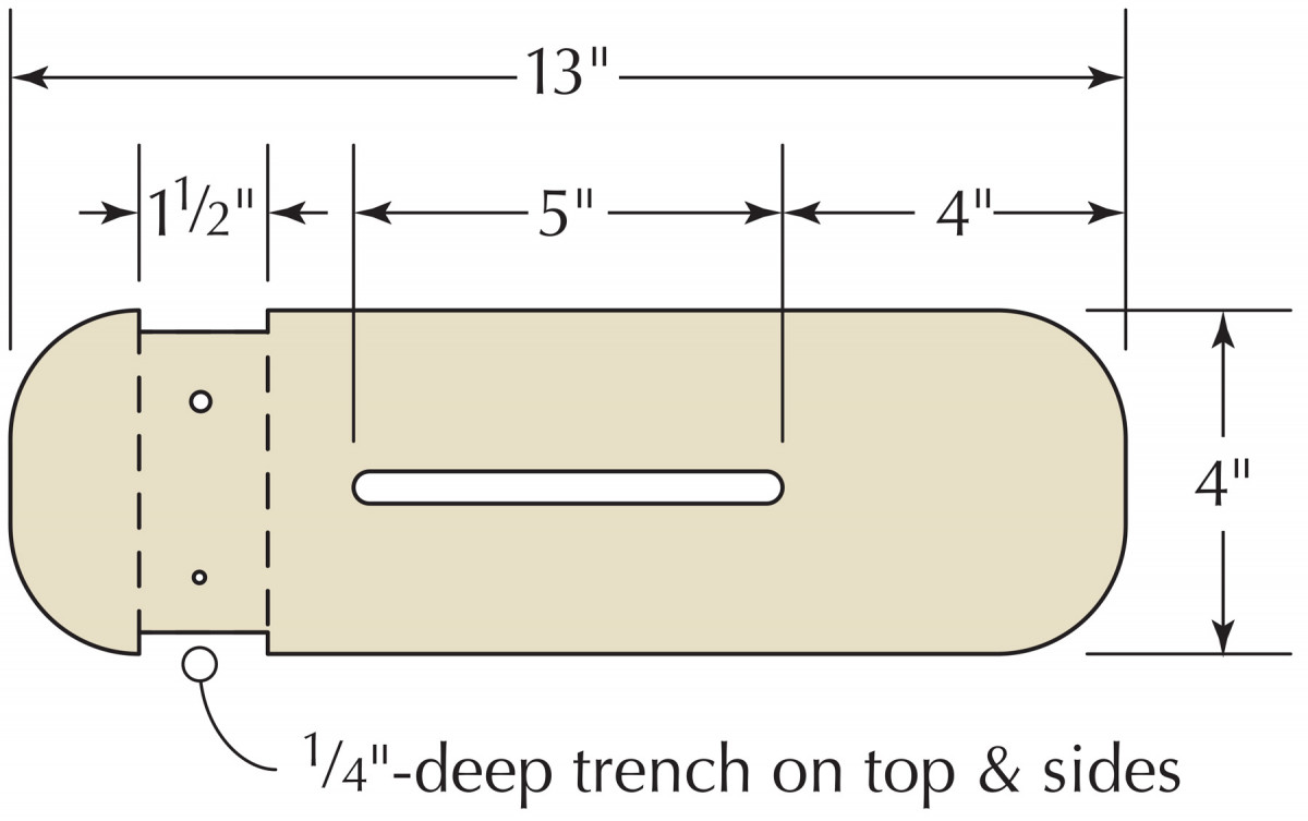
❏ 1 Tool rest 11⁄2 63⁄4 12 Pine 1⁄2” chamfer, front
❏ 1 Tool rest support 11⁄2413Pine
❏ 1 Tool rest bottom 3⁄4 4 6 Pine
❏ 1 Tail stock 3 5 173⁄4Pine
❏ 1 Tail stock wedge 3⁄4 11⁄4 12 Pine Tapered one end
*TBE=Tenon both ends
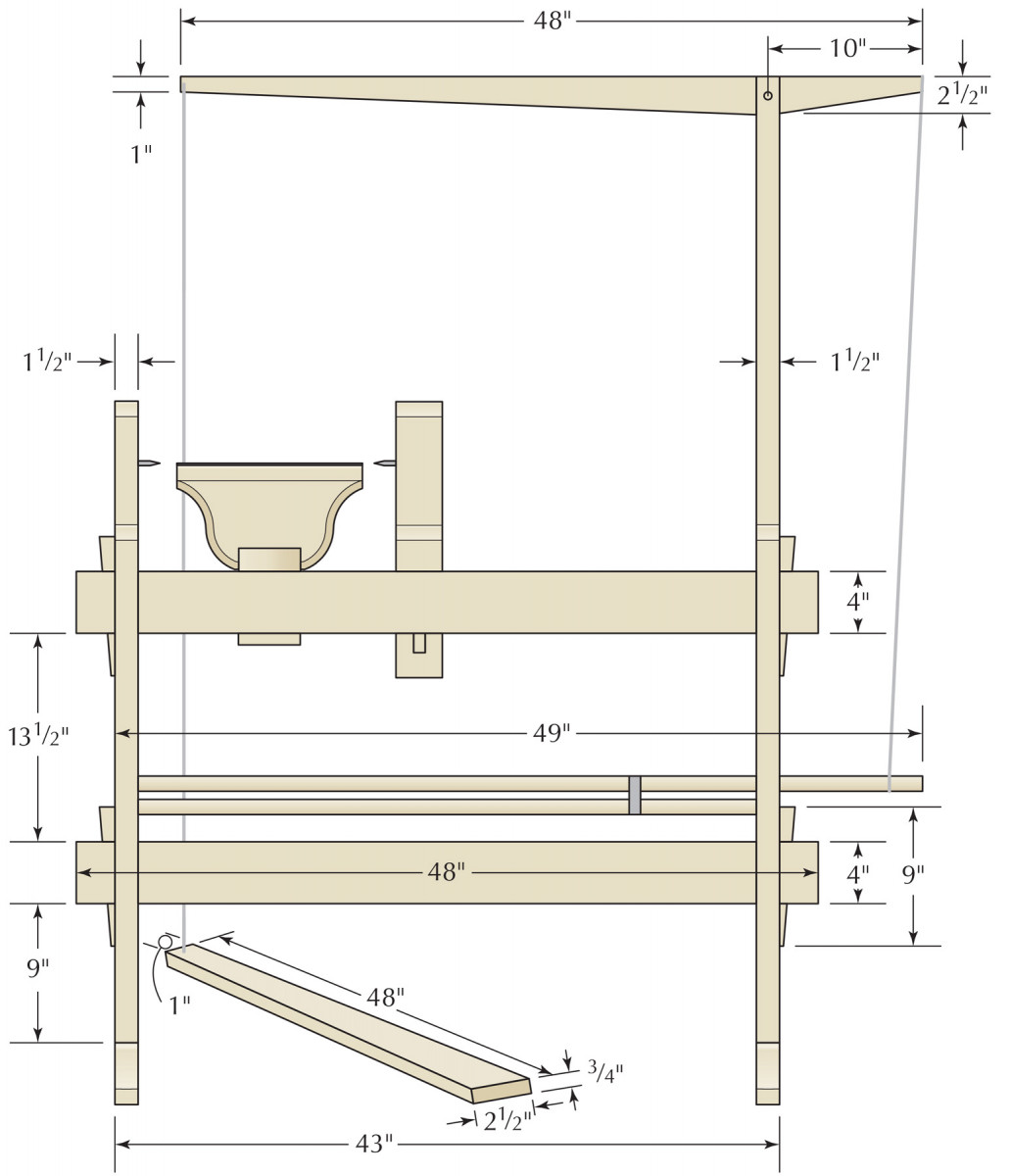
Elevation
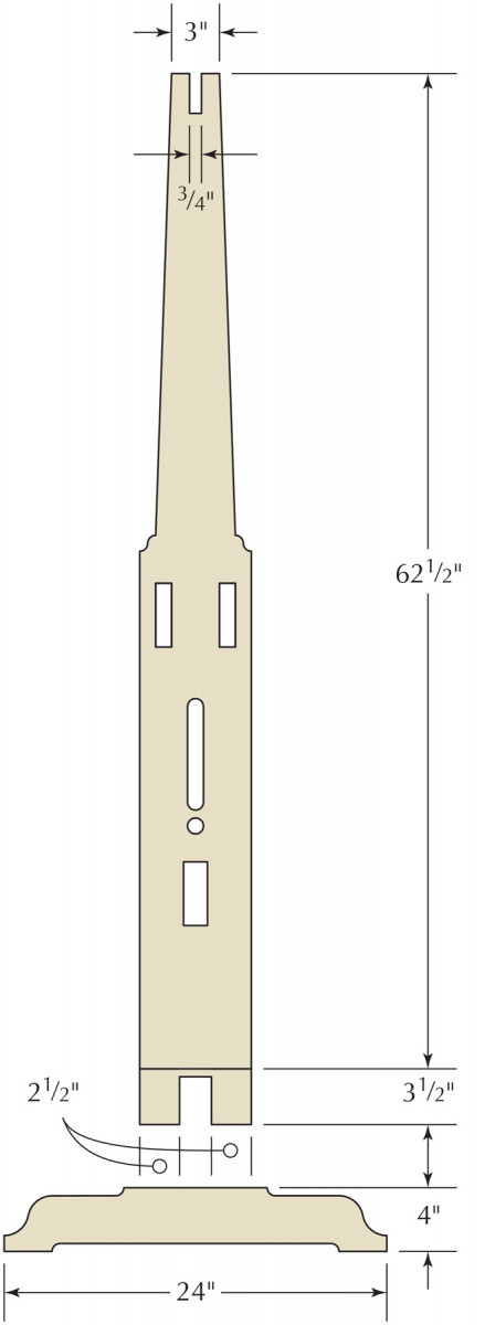
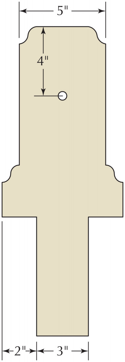
LONG post & foot Profiles
Tool Rest support plan
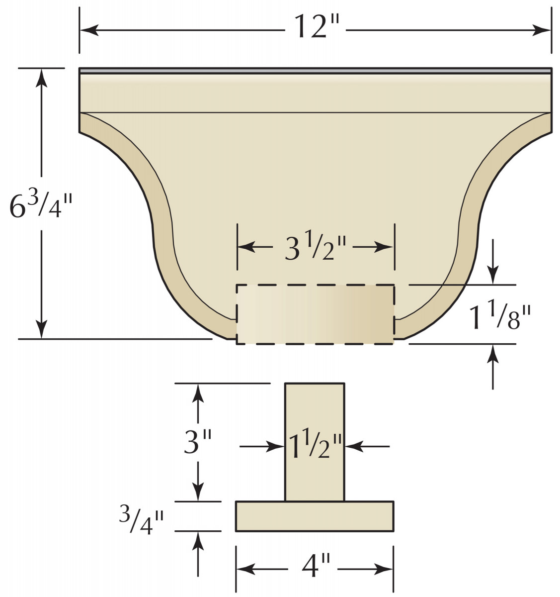
Tool Rest Elevation
Tail Stock Elevation & Profile

Tail Stock Elevation & Profile
short post & foot Profiles
Wedged Tusk Tenons
Wedge issue. Trace the wedges on the cheeks of the protruding tenons. Bore and chisel their mortises, making an easy fit to the sides and adding extra space to the back.
The wedges through the tusk tenons on the ends of the rails look great and lock the frame together firmly. To work at all, however, the wedges do need that extra clearance on their backsides so they can push ever harder against the posts as they are tapped down – rather than locking up in a too-precise mortise.
From stout wood, rip out six,3⁄8“-thick wedges, 9″ long, 1” broad at one end and tapering to 1⁄4” at the other.
Drill for coves. Clamp the foot blocks together and bore through their intersection to leave nice cove cuts for the ends of the relief cuts to follow.
With the frame assembled and the rails fitting flush to their shoulders, place one of the wedges against the cheek of a protruding tenon as it will sit when driven home. Trace the wedge’s sloping edge onto the tenon cheek then trace a second line on the cheek running flush against the post.
Remove the rail from the post and carry the lines traced from the wedge around the edges of the tenon. On the back line, the one that was flush against the post, add in that extra clearance – 1⁄8” or so. Set a mortising gauge to run a centered 3⁄8“-wide pair of tracks to guide your auger and chisel, then chop the mortises.
On Your Feet
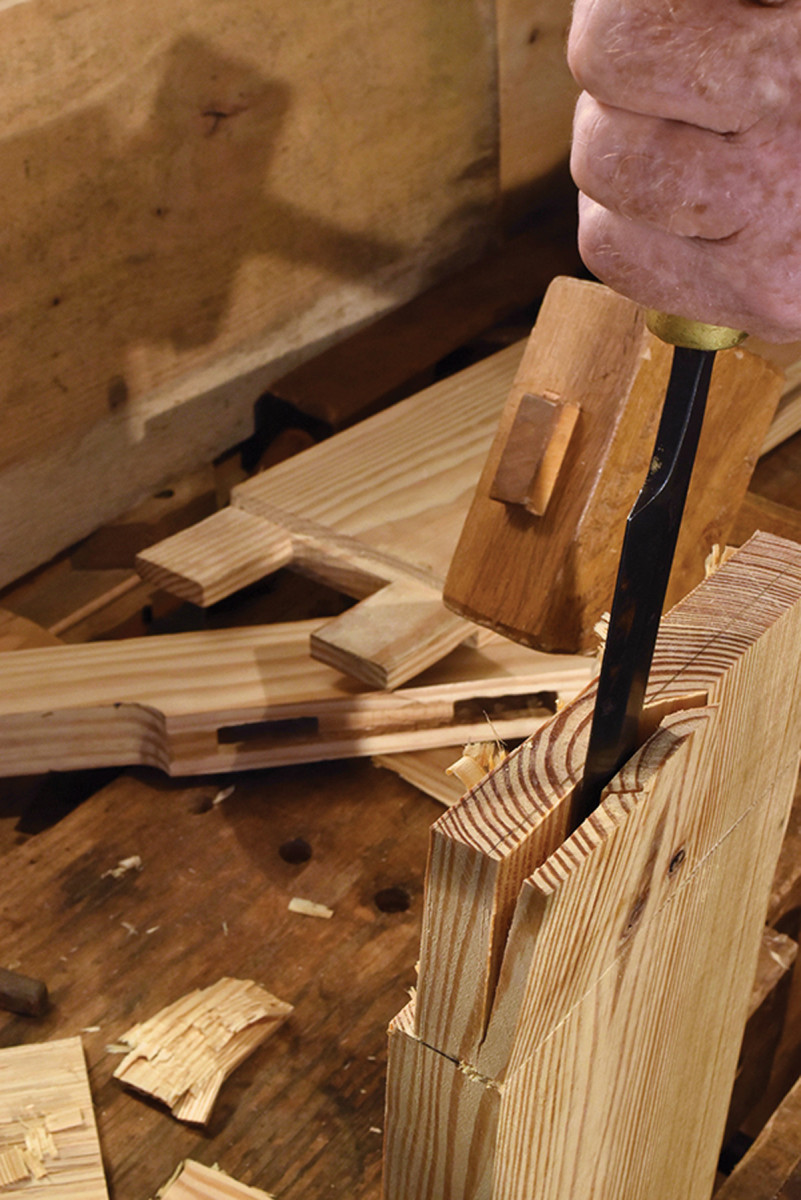
Split ’em. The haunched, double tenons on the posts start as one big, broad tenon. In this case you might saw the shoulders first then split your way back to the line.
You get to enjoy a nice trick before you begin cutting the joints to connect the feet to the posts. To give them more of a pedestal shape, the tops and the undersides of the feet are relieved by 1⁄2” or so. These cut-aways terminate in cove cuts, readily made, two at a time, by the same auger you used to make the mortises in the frame.
Clamp the foot blocks together (base to base) and bore through them both, setting the lead screw right where the two pieces meet. Bore until the lead screw just pokes through on the other side, then flip the clamped-together pieces over and restart the auger in the poke-through spot. Continue the boring to connect with the other side.
Reset the feet with the other edges clamped together and bore the second pair of holes. This process leaves four semi-cylindrical cuts in each foot that will make smooth, coved shoulders at the ends of your saw cuts.
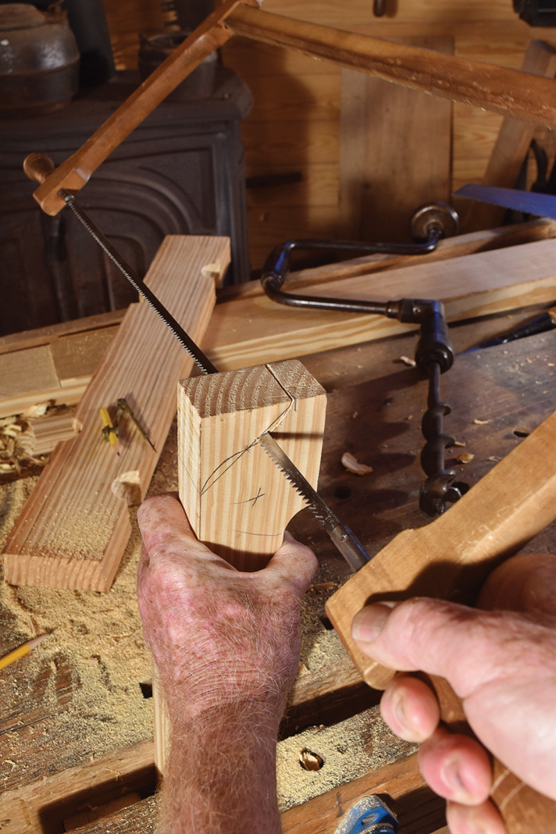
Ogee! Set the compass for half the length of the baseline. Strike short arcs from the midpoint and from one end of the baseline. Set the compass at this intersection and strike an arc forming half of the ogee. Repeat on the opposite side. Then cut.
The joint connecting the foot with a post must be broad-based for stability, but must not overly weaken one component or the other. The haunched, double tenon on the post does the trick by leaving a section of wood intact in the middle of the mortise.
Start with a broad, centered, 5⁄8“- thick tenon, then cut out the intervening wood with a turning saw. Rather than rip-sawing the cheek of such a large tenon, here you may want to saw the shoulders first then split and shave your way down to the final thickness.
Do make an exploratory split about midway into the waste to get the run of the grain before you start working closer to the tenon. When you finish the tenon, lay it across the foot and trace around it to locate the mortises to match.
The 14 ogee shoulders in this design go a long way toward making the lathe look right. The ogee is the ancient, wave-shaped recurve (laid out with a compass), as you can see in the foot illustration.
On the feet, the ogee curves are large enough in proportion to the thickness of the stock that they readily take shape with a turning saw. The smaller ogees on the frame, and particularly the ones on the thick tailstock, are better cut with a gouge and chisel. As you lay out the ogees, you might reflect on the mechanical kinship of the rotary tools – the compass and the augers, and the lathe (the machine that you are building with them).
Spring Poles, Rocker Arms & A Magic Ring
Keep on rockin! The light pine rocker arm needs a metal bushing to keep it from wearing loose.
Sturdy frame accomplished, now build in the moving parts. Whereas for the frame we wanted heavy wood for strength and stability, now we need a light but stiff rocker arm that won’t dampen the action with excess inertia.
The rocker arm pivots on a 1⁄2” iron rod with a sleeve bearing inserted to protect the soft wood. The rod and the sleeve are usually hiding somewhere in the lots-of-little-drawers-write-the-number-on-the-bag section of your hardware store. You will need to cut them down to size with your hacksaw.
The rocker arm pivots within a U-shaped slot at the top of the tall post. Find the top center of the tall post and draw a line straight down from it to the center of the space between the rail tenons. This becomes the centerline of this 3⁄4“-wide slot.
Use the rocker arm itself as the layout guide for the lines across the top, end grain of the post, keeping it in line with the rails below as you trace along the sides. Bore the 1⁄2” holes for the shaft through the post as accurately as you can, using a square and an assistant to check the work.
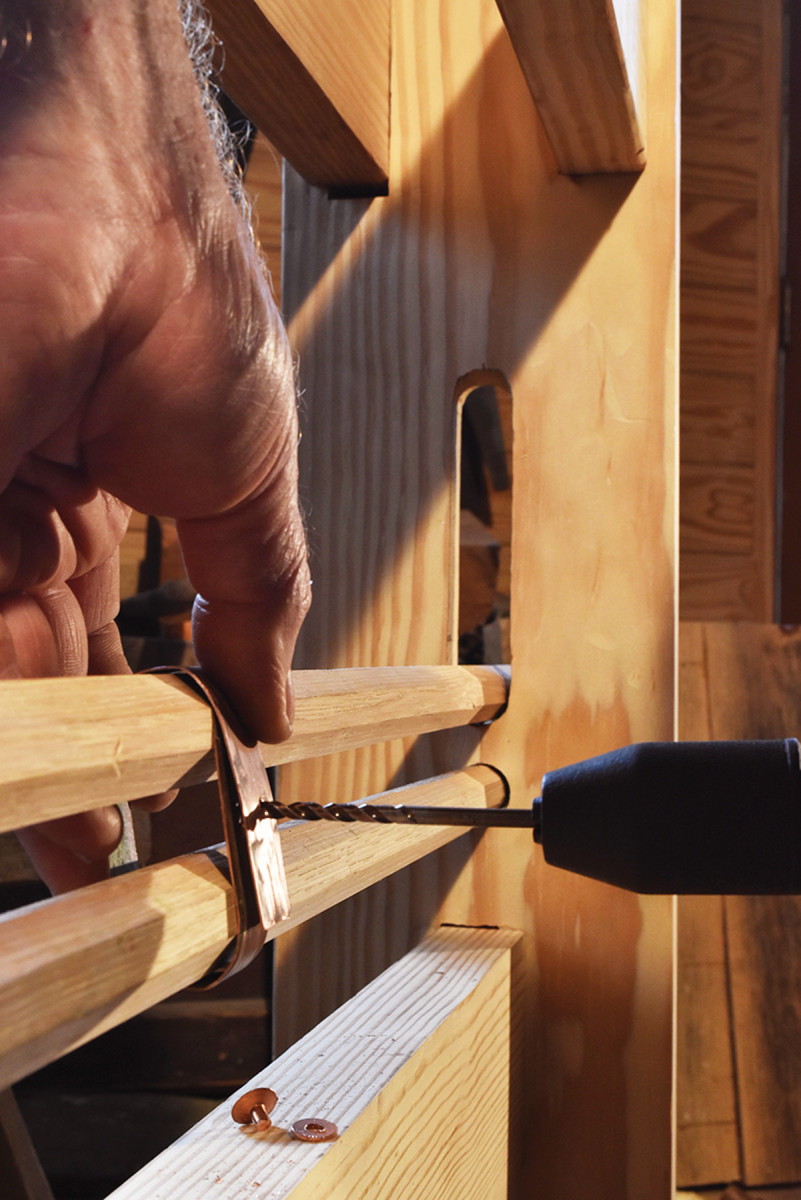
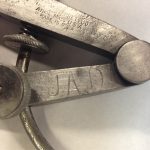
Oooo shiny! Wrap a copper strap around the spring poles and drill through the overlap. The rivet and washer came from a farm store where they are sold for harness repair.
Ash, oak and hickory do well for the spring poles, but whatever stiff wood you can find will get you started – cut off mop handles if you have to. Fast-grown hickory or oak is stiffer than slow-grown wood with lots of tight growth rings. Bring the poles down to 1″ square, then drawknife and plane the corners off to form an octagonal cross-section. The lower pole should fit completely within the frame, but the longer one has to reach out about 6″ through the slot in the tall post.
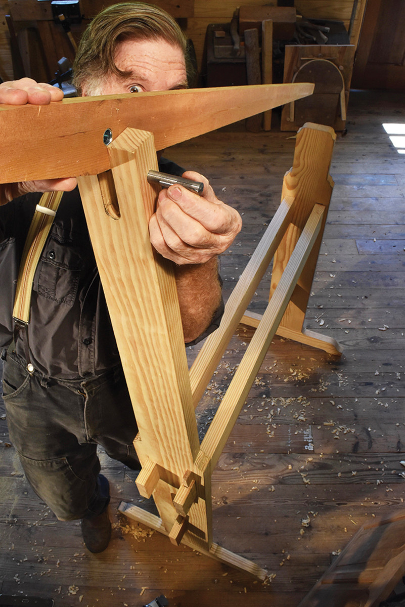
The magic in this lathe centers on the movable ring linking the two spring rods. Sliding the ring from left to right changes the combined spring strength from weak to wow, allowing you to match the inertial resistance of the workpiece with a spring strength that keeps the turning action lively and fast.
A simple knotted cord would do for the ring, but a copper band gives a bit of flash. Saw a scrap length of 1⁄2” copper pipe in half down its length and flatten out one half into a stout strip. Bend it to fit easily around the two rods, drill through the overlap and rivet it shut.
One more step and you can test the spring action. I connect the spring to the rocker arm with a heavy wire rod (but I still seek a light wooden, or a better-looking metal, connecting rod). Avoid anything that would be stretchy and dampen the energy of the spring poles.
Tail Stock, Tool Rest & Centers
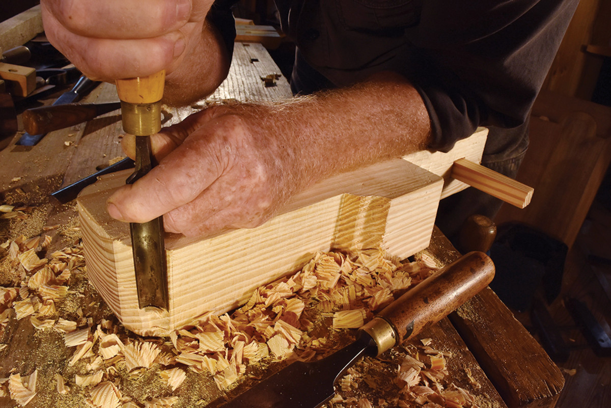
Make it thick. Glue up the tail stock from two layers of plank. The small, deep ogee shoulders are best pared in with chisel and gouge rather than cut with a turning saw.
If you can get thick stuff for the tailstock, excellent. But in keeping with the mandate for the readily available material, I use two good 18″ lengths of glued-up plank.
Make the wedge for the tail stock in the same way as the tusk tenons on the rails, but 3⁄4” thick and with enough sticking out front and back to make it easy to hit with a mallet. This wedge gets a lot of use as you adjust the pinch of the two centers.
You depend on the tool rest for proper turning, so don’t neglect it. A wobbly tool rest makes good work impossible and the blame may fall on the whole concept of spring-pole lathe turning.
Your tool rest must be quickly loosened for adjustment but just as quickly locked in place. It has to be wide enough to not require frequent shifting left and right, but not so wide as to be unstable. The T-shaped under-piece keeps the 7″-long, 3⁄8” carriage bolt (secured with a fender washer and wing nut) centered between the rails, and the slotted L-shaped upper half allows you to position the rest properly distant from the turning wood. An inch-wide metal strip screwed on the top edge presents a smooth, narrow fulcrum for the turning tools.
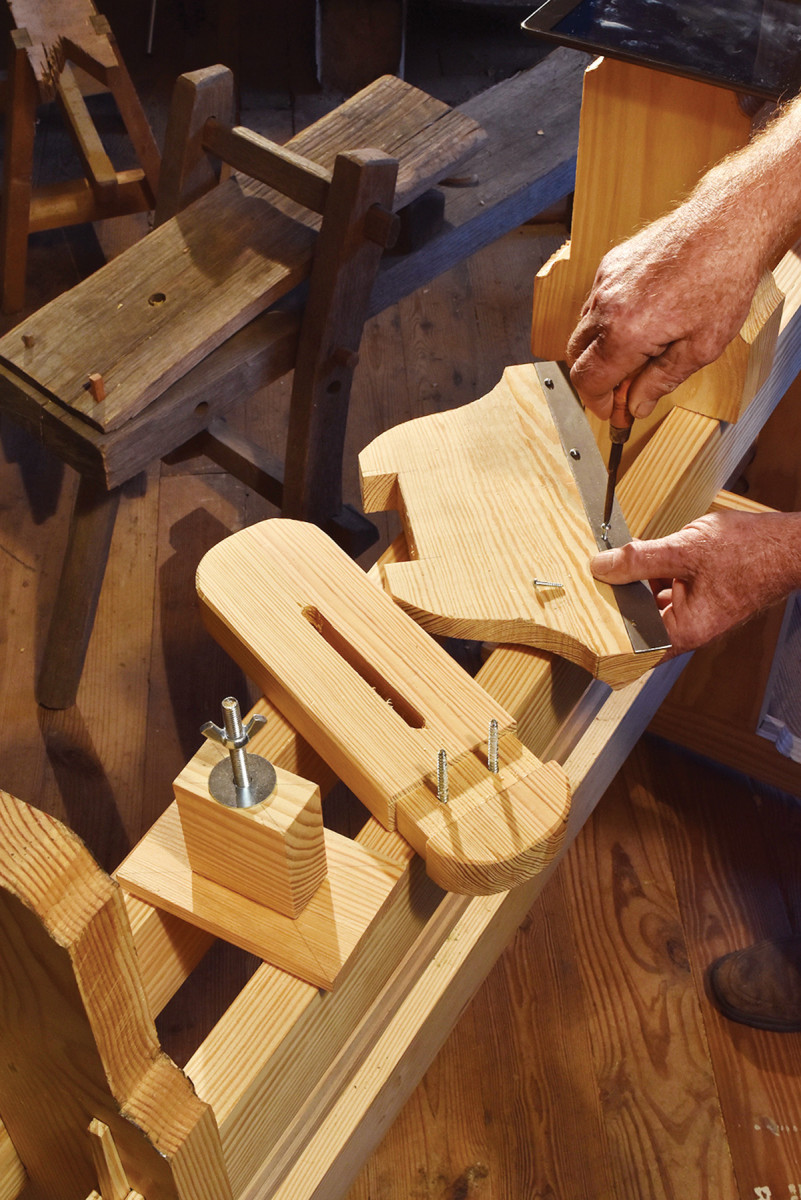
Smooth moves. A metal strip makes smooth bearing for the turning tools on the rest. Build the tool rest stoutly!
This tool rest does not have a ready height adjustment (you could do it with shims), but I have found it satisfactory if the top edge is about level with the centers. Make the tool rest first, check it for level, then use it to find the locations of the centers on the head and tail stocks.
The centers must be perfect, polished cones or they will constantly enlarge their seat in the end grain of the turning piece and allow it to wobble.
I have my students buy inexpensive #1 Morse taper dead centers for their lathes, but if you are ready for more metal-working, the remainder of the 1⁄2” rod used for the rocker arm can be turned into the centers for your lathe.
Fret not about the lack of screw adjustments on the centers. Like a wooden plane, you can adjust the pinch of this lathe perfectly well with taps of a mallet or, more often, with the handle of the turning tool.
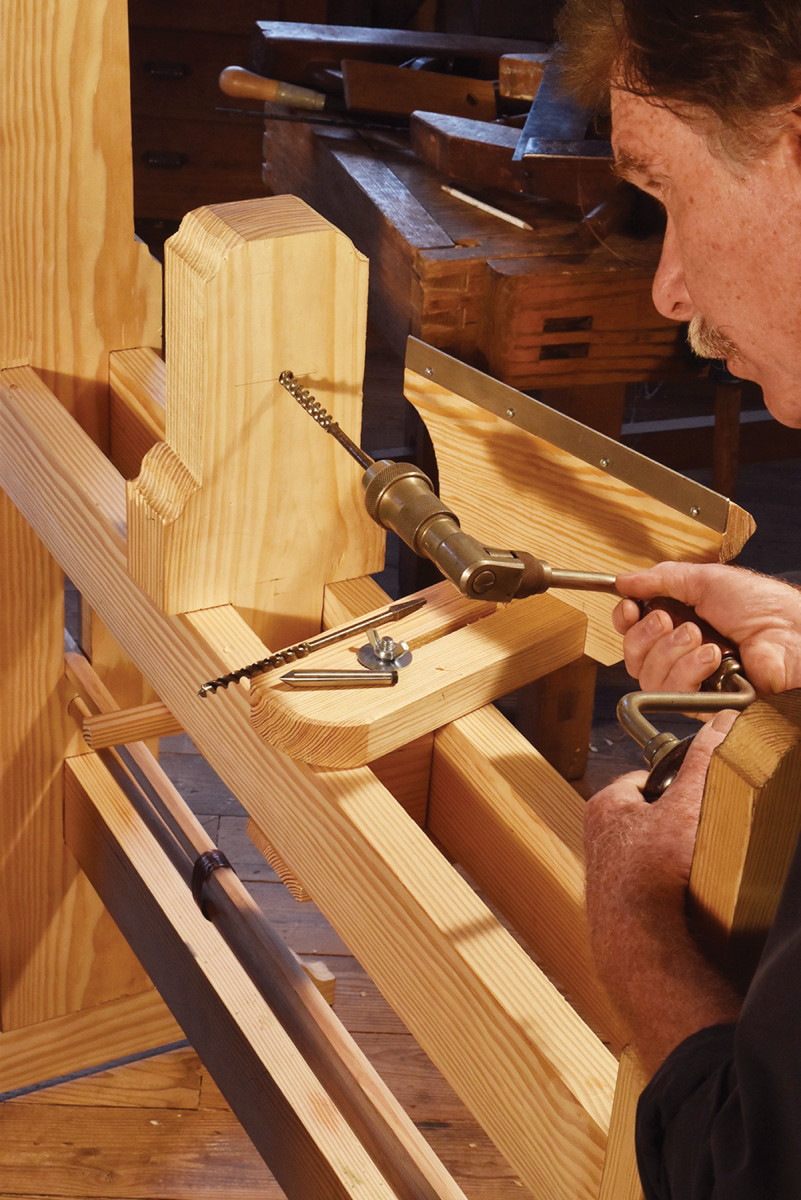
What a bore. Bore the seats for the centers with the brace carefully aligned with the lathe’s axis of rotation. The tapered centers seat well in a 11⁄4″-deep 7⁄16″ hole followed by a concentric 3⁄8″ hole.
Like the centers, the drive cord is a demanding part of the lathe. A natural fiber cord frays very quickly from rubbing against itself – but it will get you started. The best cord is the 3⁄16” to 5⁄16” round leather belting used for treadle sewing machines. Pass the top of the cord through a hole bored in the tip end of the rocker arm and stop it with an overhand knot. Run out a 6′ length and attach the end to the far tip of the foot treadle.
I have never made a foot treadle any more elaborate than a plain four-foot stick for this lathe, probably because I was so eager to try it out that I went for the quickest solution. Spring pole lathes do commonly have proper treadles, usually a triangular set of sticks with one side hinged to the floor. Whatever you use, make the treadle light enough that you’re not fighting its inertia, but stiff enough to keep the turning action lively and decisive.
Attachments
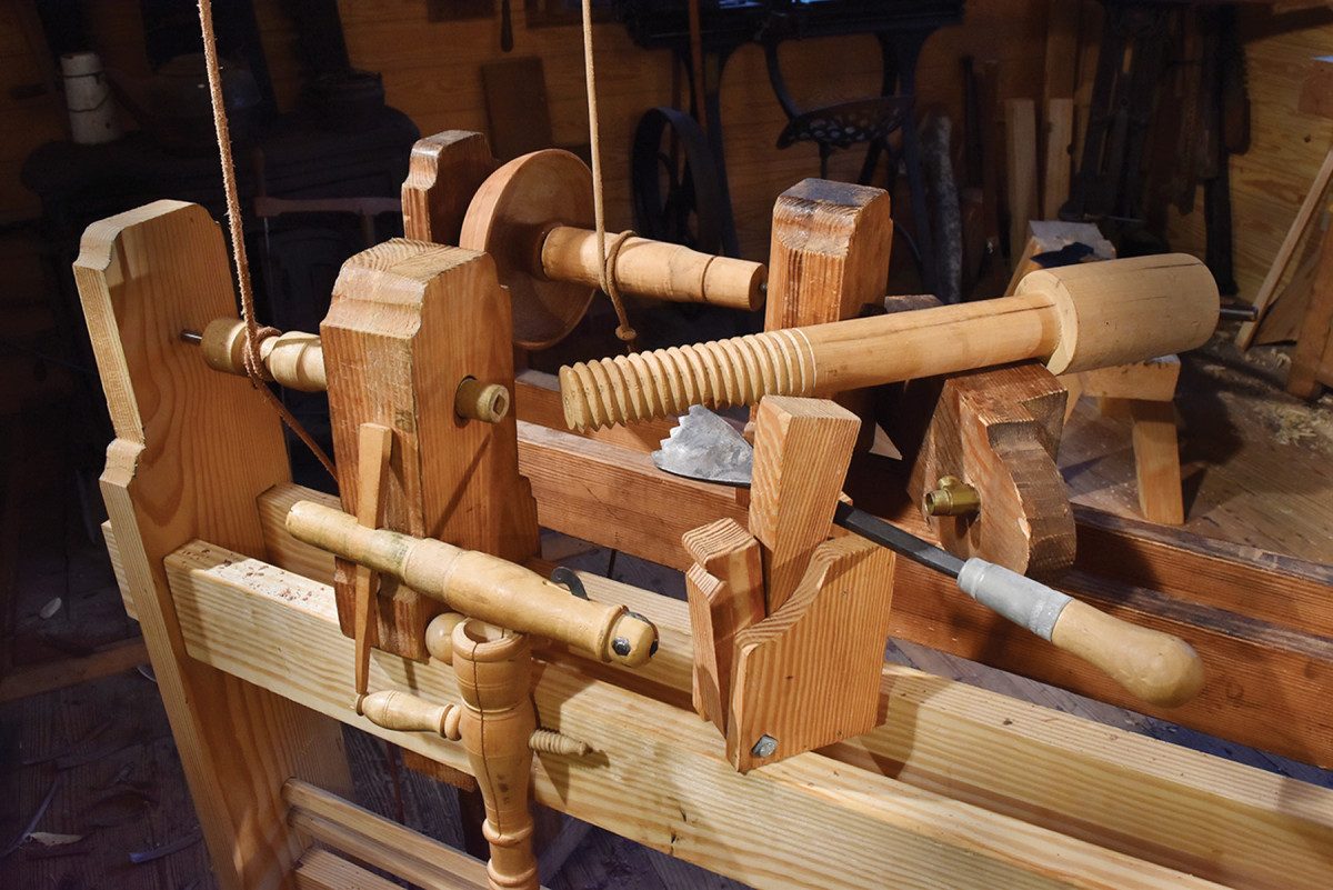
What is a lathe without attachments! Clockwise from left: Mandrel and head stock for turning wood too slender to work directly with the drive cord. (One end of the slender wood chucks in the square socket and the other turns on the dead center in the tail stock.) A spike mandrel for bowl turning. A thread chase for making bench screws. A hollow center tail stock, made from a sharpened brass plumbing fixture, for boring out flutes and such. A constant pressure steady-rest for slender stock. A socket scraper resting on an example of the ball and socket joints it helps to make (It mounts in the tail stock.)
— RU
Turning
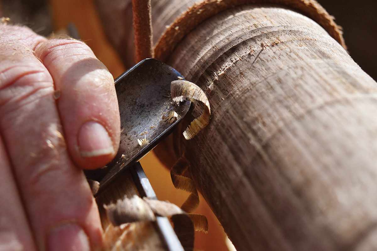
Find the sweet spot. A proper skew cut with the gouge leaves a spiraling shaving as the bevel rubs on the wood. The drive cord passes around the work on the side facing the turner.
You could turn kiln-dried wood, just as you could eat only crackers, but the full flavor of woodturning is only found in fresher stuff. With wedges, hatchet and drawknife, rough out some fresh turning stock to perhaps a 3″-diameter cylinder (a pretty nice cylinder for this first time out) about 18″ long. Find the approximate centers on both ends and dig out a small hole with the point of a skew turning chisel.
Rub some wax in the holes, wrap the lathe cord around the stock so it passes on the front side and pinch up the stock between the centers. Tighten the centers by tapping in the tail stock and driving in the wedge. You will need to tighten the pinch several times during turning as the centers find their final seat.
Set your toe on the treadle about a foot from the anchored end and push down. The stock should spin toward you from the top (if it turns away from you on the downstroke the cord is passing on the wrong side).
Adjust the spring tension by sliding the ring left or right to make a lively spin on the upstroke. You can make additional adjustments by moving the connecting rod’s positions on the protruding pole and the rocker arm. Observe that the smaller the diameter of the place where the cord wraps around the workpiece, the faster the wood will spin on every stroke. Large diameter equals slower speed, more torque. Small diameter equals high speed, lower torque – just what you want.
Now for the turning, and the question: “Do you have to pull the tool back on the return stroke?”
No, you don’t, but you should certainly strive for the best turning practice. You don’t just poke a gouge into the spinning stock and scrape your way to shape. When your leg muscles and not the power plant are doing the work, you have a constant incentive to find that most perfect shearing cut.
Start with your left hand anchoring the gouge on the tool rest’s fulcrum, and slide skimming cuts from left to right over a 2″ length until you have cut down to a clean cylinder on the right end of the stock.
Now try some proper turning, making sure that the bevel of the gouge or chisel rubs the wood as the cutting edge makes a shearing cut across the grain, leaving a spiraling shaving. Always work from the larger diameter down to the smaller.
The only concerns specific to the spring pole lathe are:
■ Don’t cut the cord with your gouge!
■ Lift your foot high enough to get multiple rotations of the stock on every stroke.
■ Keep the centers pinching the wood (a rattling sound means you are loose).
■ Be generous to the folks who take an interest!
This last is so important. Some may find muscle-power machines challenging to their world view, and if they poke fun at you, you might be tempted to poke back. For example, to the question:
“Hey! Where’s the switch?”
You might be tempted to respond: “Right here!” (Said while picking up a hickory stick and taking a swat at the questioner’s legs.)
But that would not be nice.
Model: Download a free SketchUp model of the pole lathe.
Here are some supplies and tools we find essential in our everyday work around the shop. We may receive a commission from sales referred by our links; however, we have carefully selected these products for their usefulness and quality.