We may receive a commission when you use our affiliate links. However, this does not impact our recommendations.
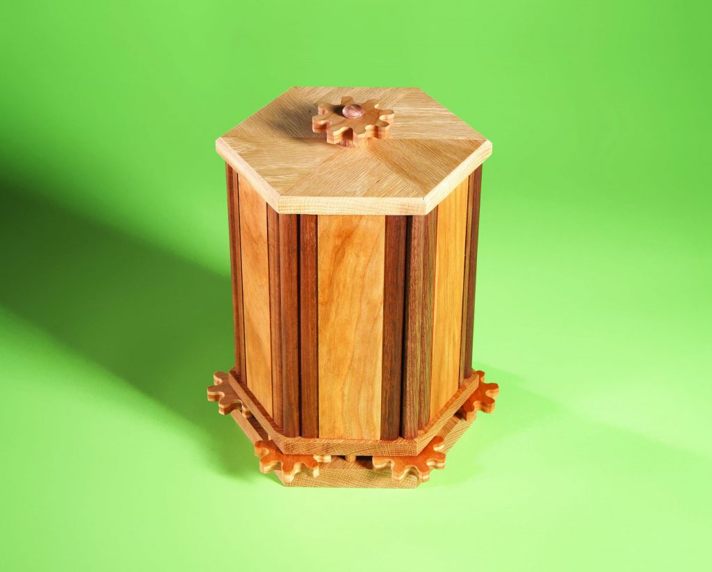 My rotary box started out as a solution to a specific problem. Back when I was playing poker with my buddies, someone suggested that we needed a fitting storage container for our boys-night-out cigars. The box came to me in a flurry of CAD calculations and sketching and was an instant hit.
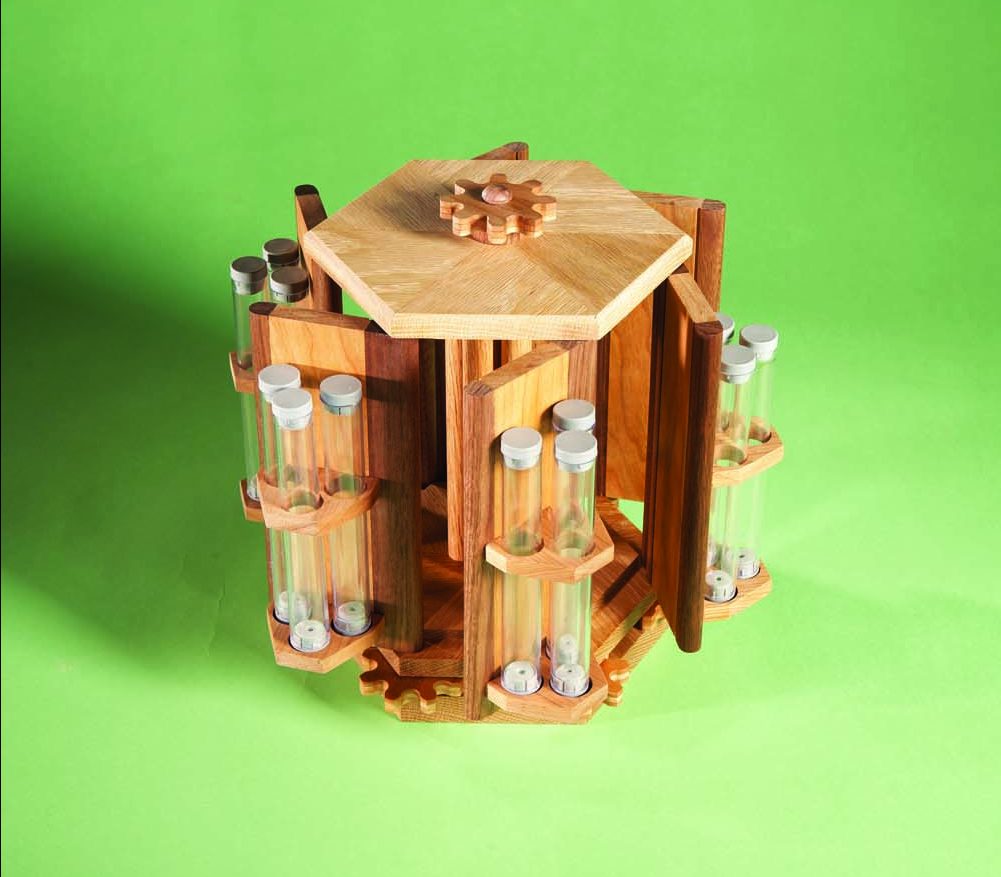
Turn the gear-shaped knob on top of the box and all six doors will open at the same time.
But when doctors and spouses pointed out that cigars are not necessarily the path to true happiness, the box became nothing more than a conversation piece. As if the loss of a mission statement wasn’t enough, it slowly began to bind, warp, and in general tear itself apart.
Hope springs eternal, and one day a pen collector and turner suggested that I revisit the project as a home for his most-valued specimens. Eureka! My box had a new reason for being. I enlisted the help of my brother Pete, who is a stickler for accuracy. Learning from my mistakes, he built a new box that still works fine.
As you can see, all the doors of the box open and close at the same time. One large gear turns six smaller ones—one for each door. Making the gears and drilling the holes for their axles is exacting work, but you really don’t have to be ultra-precise. It’s not like you’re making a watch!
Pete figured out the trick to synchronizing the doors: Don’t glue the gear’s axles into the doors—just make them a tight fit. This way, if one or two doors happen to lag behind the others, you just rotate them a bit by hand. Once the box is tuned, it should stay in tune.
If you get the bug to build this project, you could start with the gears, the octagonal plates or the doors. It really doesn’t matter. We’ll start with the doors, just to get them out of the way, and then move on to the more esoteric, fun stuff. A word of warning—once you start making projects with gears, you may get hooked. I sure am!
Quick Start: Deconstructing the Box
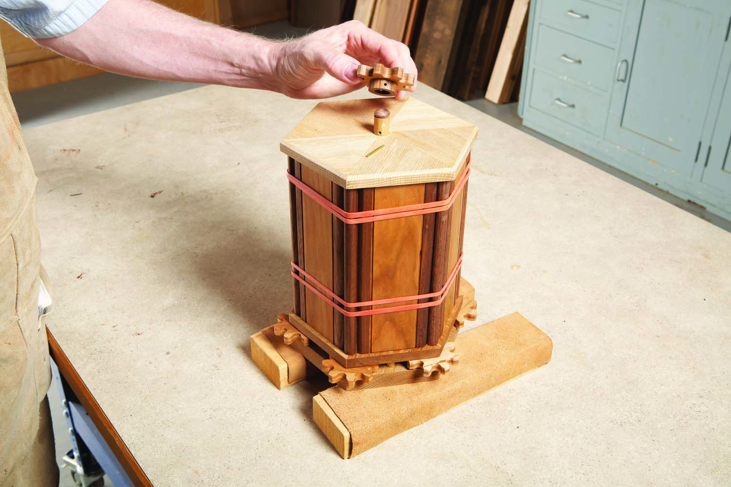
Step 1. Remove the gear-shaped knob on top of the box.
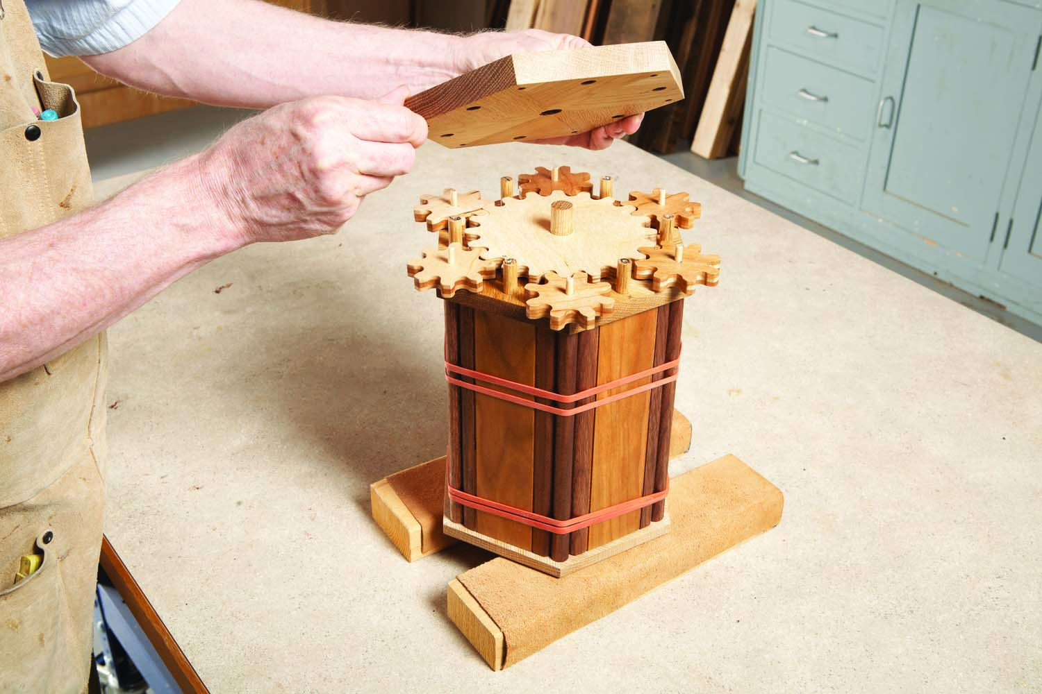
Step 2. Turn over the box and unscrew the bottom plate.
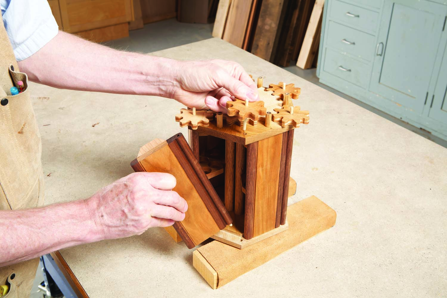
Step 3. Remove all of the small follower gears and the doors.
Step 4. Pull out the large driver gear.
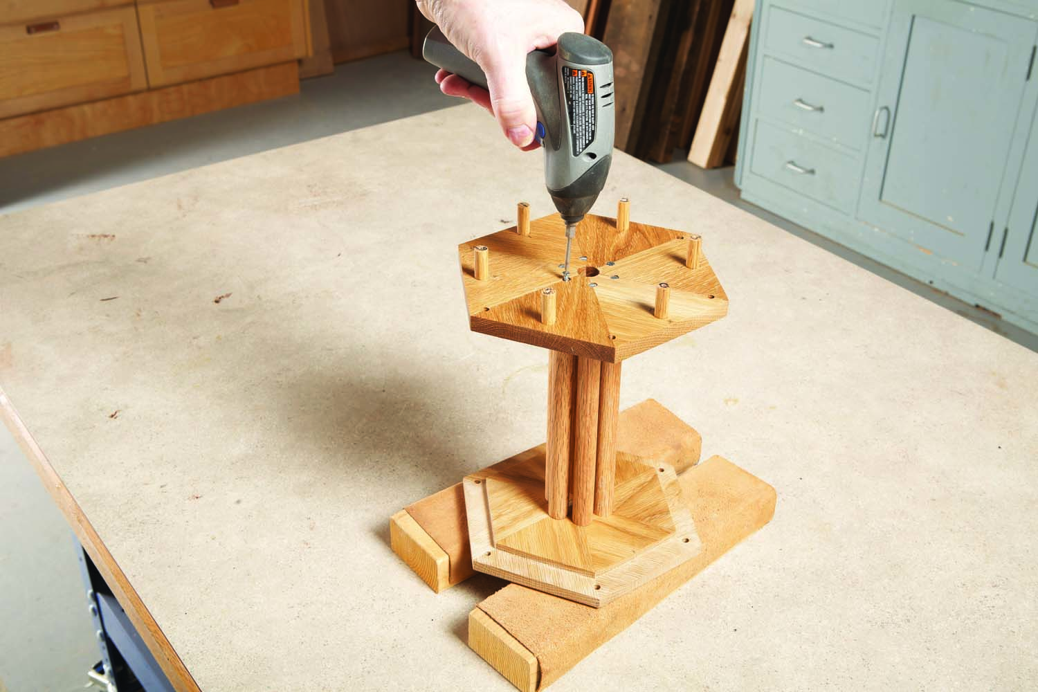
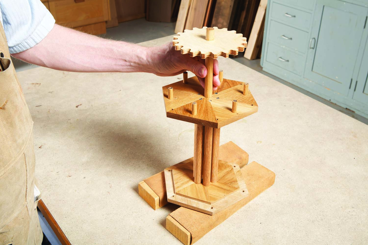
Step 5. Unscrew the middle plate from the columns below.
Cutting List
|
Overall dimensions: |
|||||
|
Section |
Part |
Name |
Qty. |
Material |
Th x W x L |
|
Case |
A |
Plate |
3 |
Red oak |
3/4″ x 6-15/16″ x 8″ (a) |
|
B |
Column |
6 |
Hardwood dowel |
5/8″ dia. x 9″ |
|
|
C |
Spacer |
6 |
Hardwood dowel |
3/8″ dia. x 1-1/2″ |
|
|
Doors |
D |
Panel |
6 |
Cherry |
1/2″ x 2″ x 7-7/8″ |
|
E |
Outer stile |
6 |
Walnut |
1/2″ x 1/2″ x 7-7/8″ |
|
|
F |
Inner stile |
6 |
Walnut |
1/2″ x 1″ x 7-7/8″ |
|
|
G |
Shelf |
12 |
Cherry |
1/2″ x 2-1/2″ x 2″ |
|
|
H |
Door axle |
6 |
Hardwood dowel |
3/16″ dia. x 5/8″ |
|
|
Gearing |
J |
Driver gear |
1 |
Baltic birch plywood |
3/8″ x 5-3/8″ dia. (b) |
|
K |
Follower gear |
7 |
Cherry |
3/8″ x 2-11/32″ dia. (c) |
|
|
L |
Follower gear axle |
6 |
Hardwood dowel |
3/16″ dia. x 2″ |
|
|
M |
Drive shaft |
1 |
Hardwood dowel |
5/8″ dia. x 11″ |
|
|
N |
Washer |
1 |
Hardwood dowel |
1″ dia. x 3/8″ |
|
|
P |
Button |
1 |
1/2″ Screw plug |
5/8″ o.d. x 1/4″ (d) |
|
|
Notes: (a) Each plate is made from three blanks, cut in half. Each blank is 3/4″ x 3-5/8″ x 9″. (b) Make from 6″ square blank. (c) Make each gear from three 1/8″ x 2-5/8″ x 2-5/8″ blanks. (d) Cut standard plug so it’s shaft is 1/16″ long. |
|||||
Fig. 01. Overall Exploded View
Fig. 02. Exploded View of Door
Fig. 03. Door Details
The doors consist of three parts: center panels (D), stiles (E and F) and shelves (G). All of these parts are 1/2″ thick; you can buy pre-planed wood or mill it yourself. All of the pieces will be quite short. For safety, do all your machining on three sets of pieces that are 15″ long.
Rip and joint the panel stock to width, then rout 1/16″ x 1/16″ rabbets along its edges (Fig. 03). Trim the panels 1/8″ extra-long, then cut dadoes for the shelves.
Photo 1. Rout a board’s edges to make the door’s stiles. All stiles have a bullnose molding; the inner stiles have an additional bead.
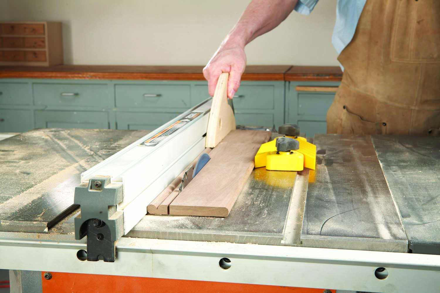
Photo 2. Rip the stiles from the board. Glue the stiles to a center panel and trim each door to final length.
Make the stiles from a piece that’s at least 3″ wide (Photo 1). Rout both sides with a bullnose bit or roundover bit. Rout one side with a beading bit making multiple shallow passes. Rip both sides to final width (Photo 2). Trim the pieces 1/8″ extra-long and glue them to the panels. Trim each door to final length.
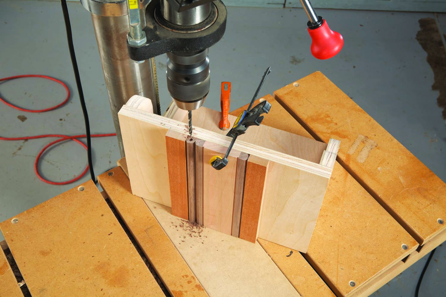
Photo 3. Drill holes into both ends of the doors for the axles that the doors will pivot on.
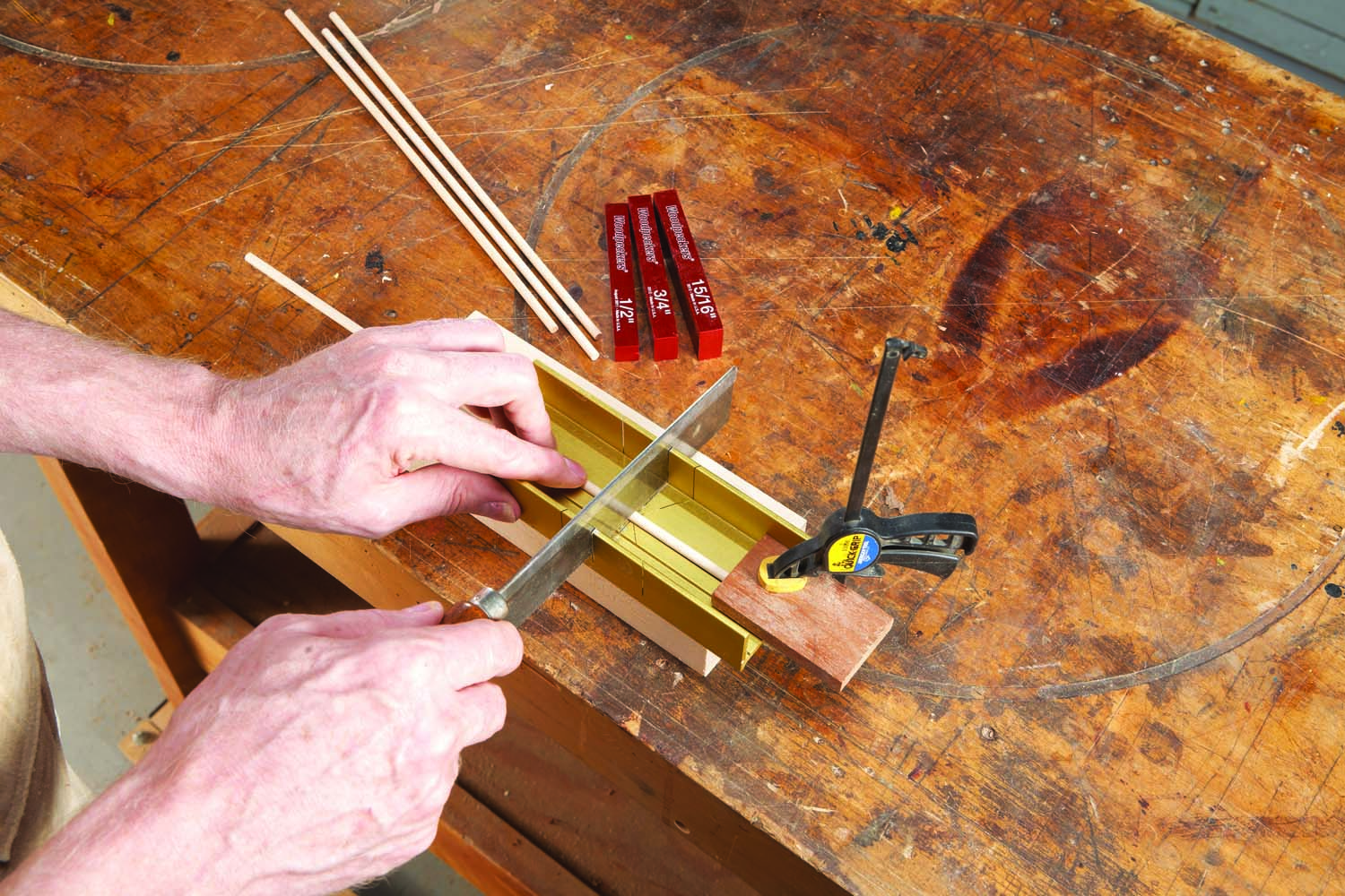
Photo 4. Cut 3/16″ dowel rod to make the axles. Use a group of setup blocks to position the stop block in a small miter box.
Build a right-angle stand for drilling axle holes in the doors (Photo 3). Carefully lay out the holes and drill. Make the axles (H and L) from 3/16″ dowel rod, available at craft stores and home centers. Cut the axles to length (Photo 4), but don’t glue them in the door. Make the shelves (Fig. 04) and glue them in place.
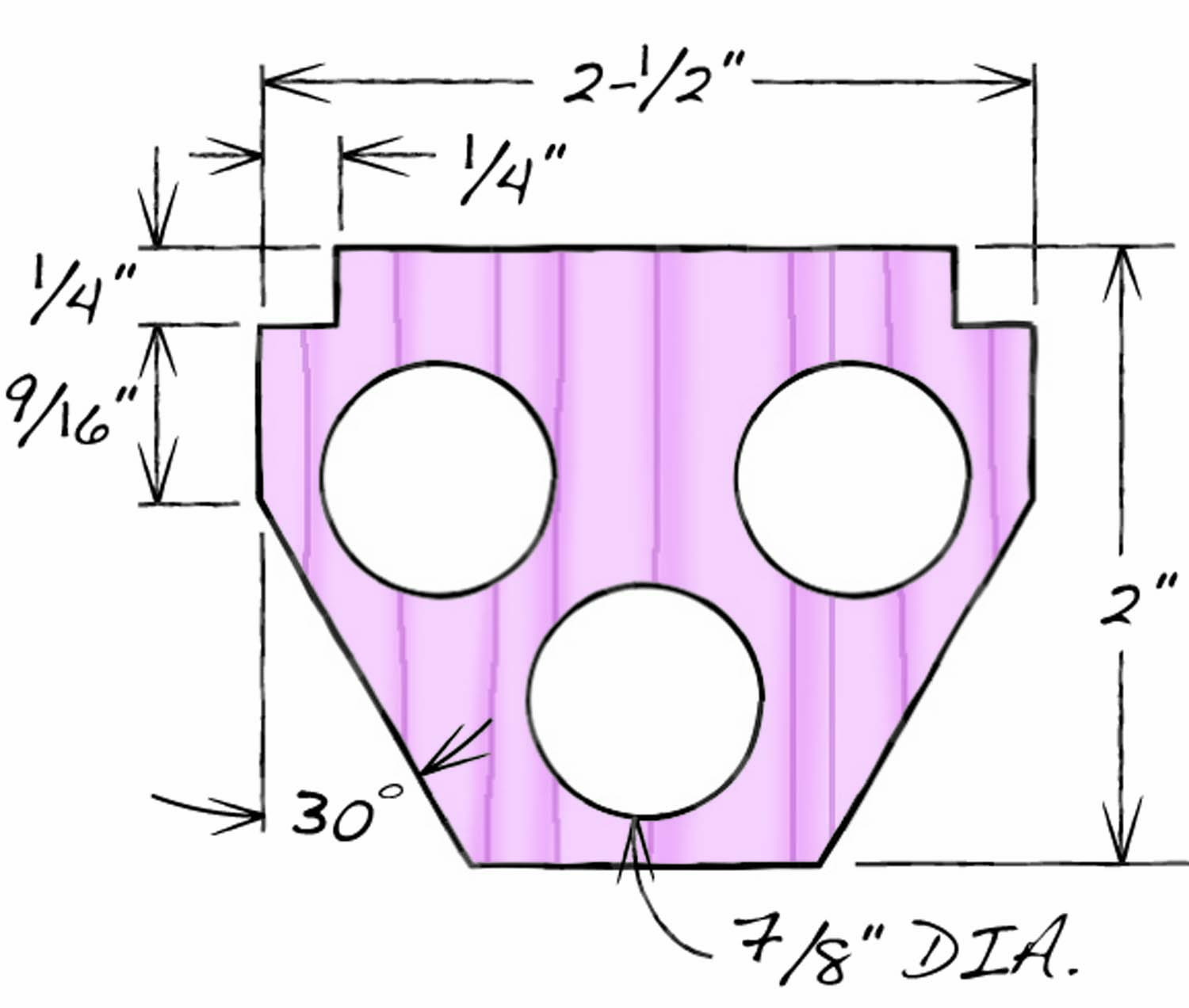
Fig. 04. Shelf Details
The procedures for making the large driver gear (J) and the smaller follower gears (K) are pretty much the same. The driver is made from plywood, however, while the followers are laminated. Let’s just look at how to make a follower, since it’s more complicated.
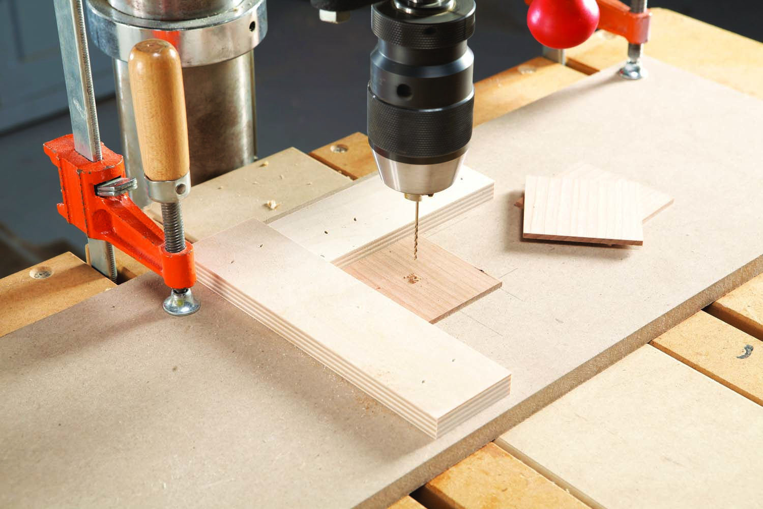
Photo 5. Drill alignment holes in the center of three 1/8″ thick squares.
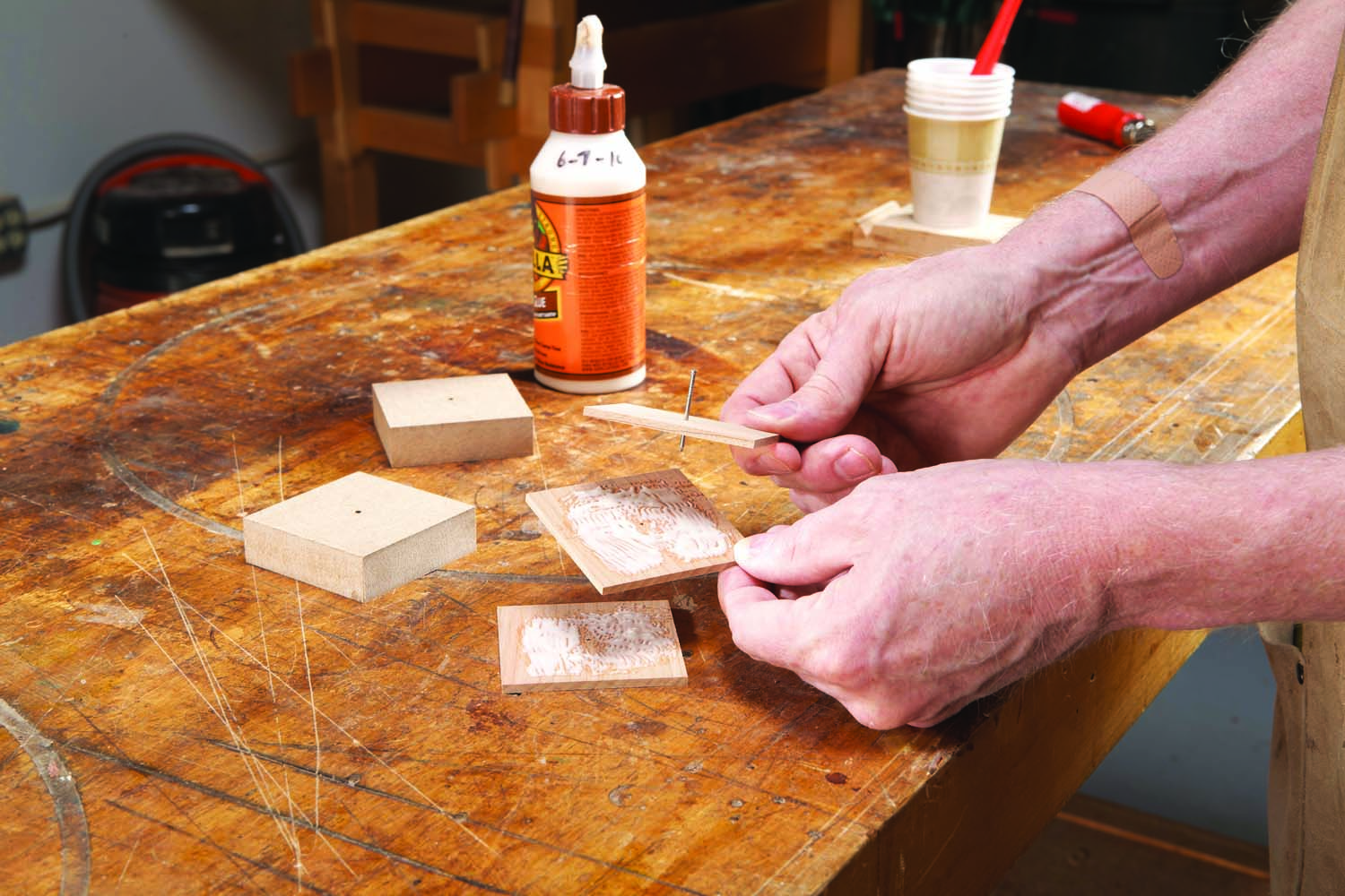
Photo 6. Insert a 3d nail through the top piece. Apply glue and rotate each piece 45°.
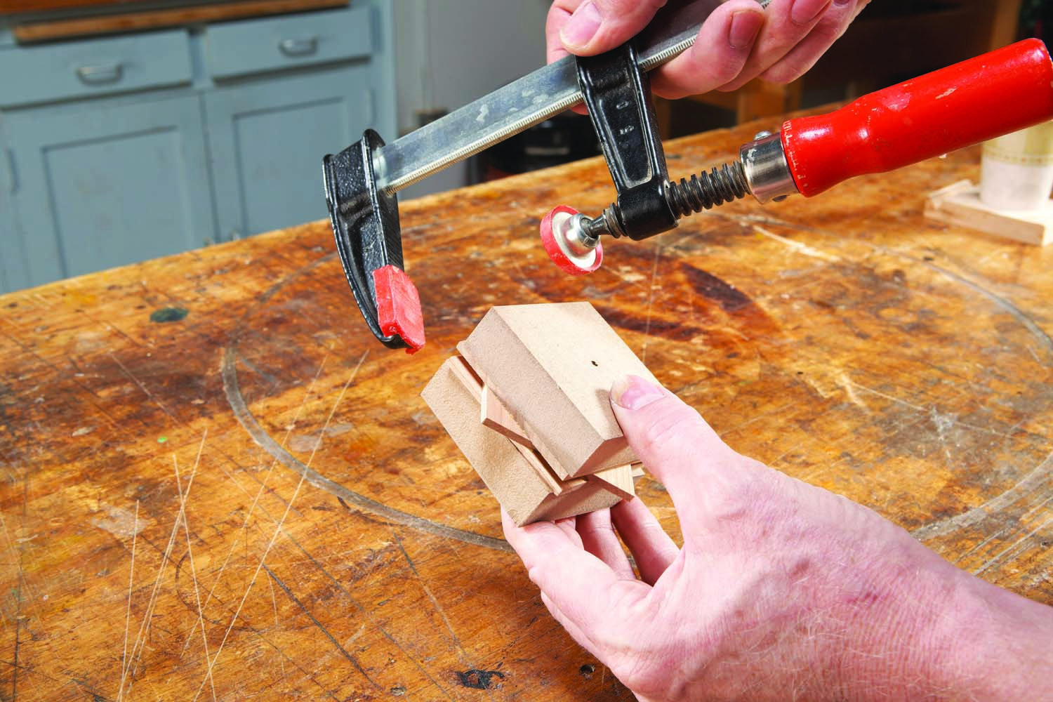
Photo 7. Clamp the stack between cauls. The nail keeps each piece centered.
Start by making 1/8″ blanks (see Cutting List). Drill small holes through the blanks and glue them together (Photos 5–7). For strength and stability, the grain of each piece must run in a different direction (Fig. 07).
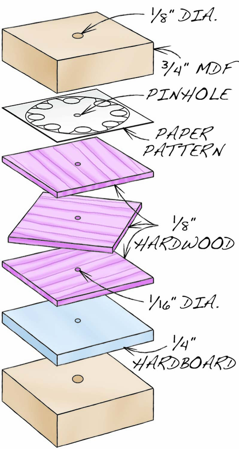
Fig. 05. Follower Gear Glue-Up
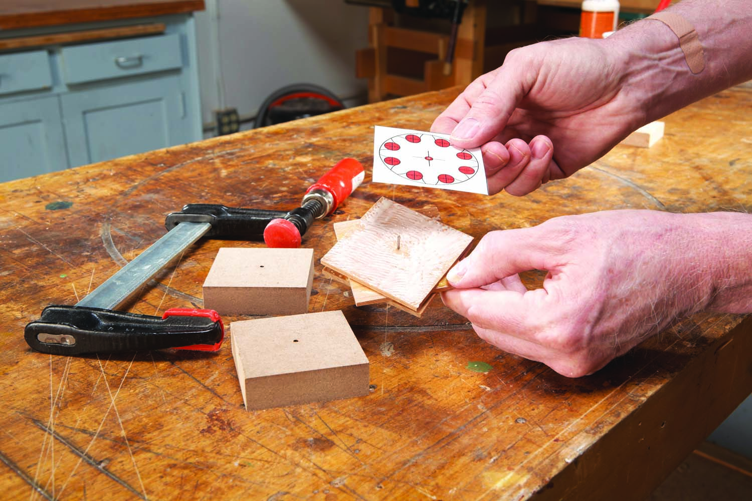
Photo 8. Glue on a paper pattern of the gear. Later, add a backer piece below.
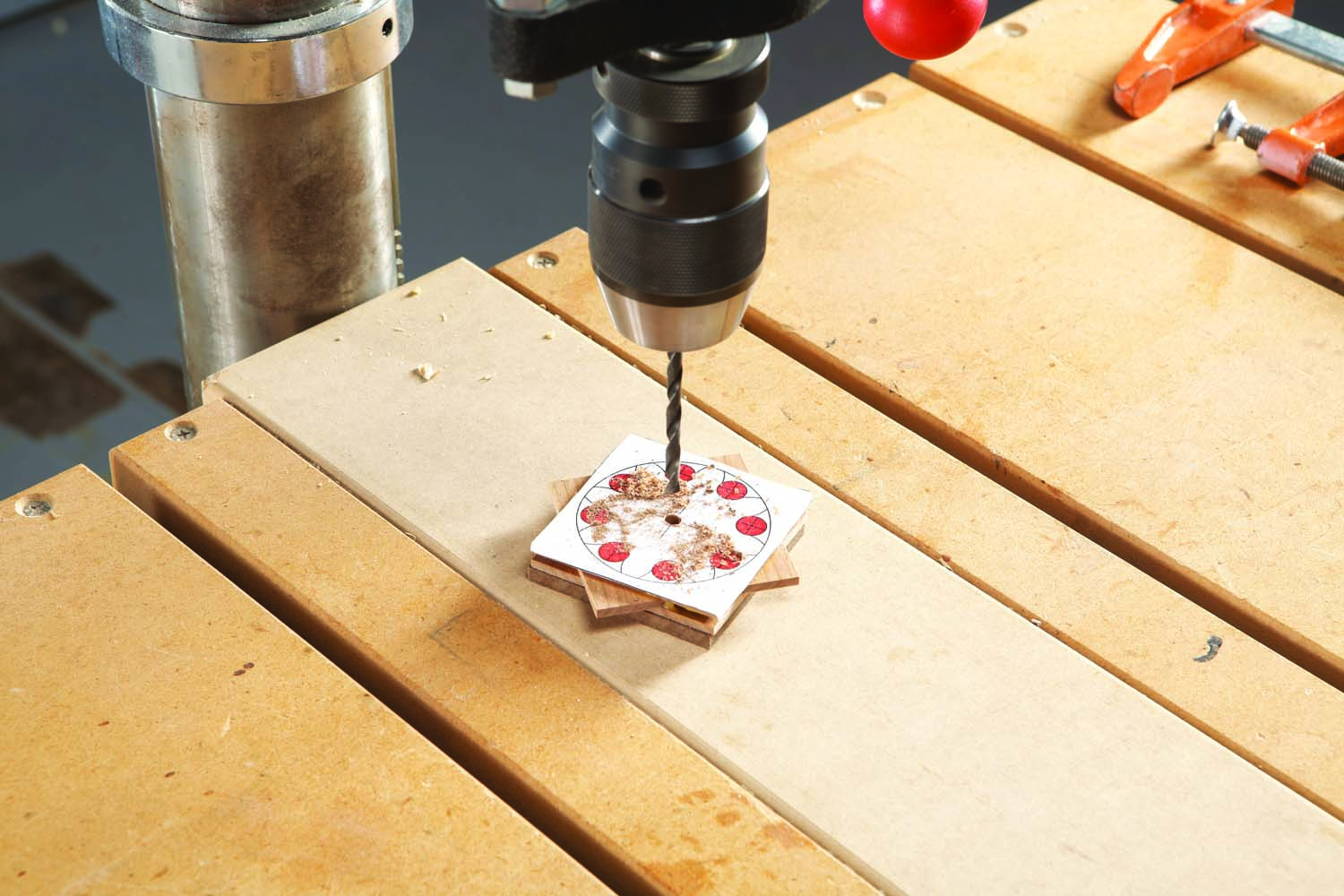
Photo 9. Enlarge the center hole to 3/16″—the size of the gear’s axle.
It’s possible to lay out each gear individually with a compass (Figs. 05 and 06), but it’s much easier to work from a paper pattern. Glue the pattern to the top of the stack (Photo 8), then use a temporary-bond spray adhesive to add a backer board to the bottom. Enlarge the hole in the stack (Photo 9), then drill the gear’s “dedundums” (see Fig. 05) using a jig (Photos 10 and 11).
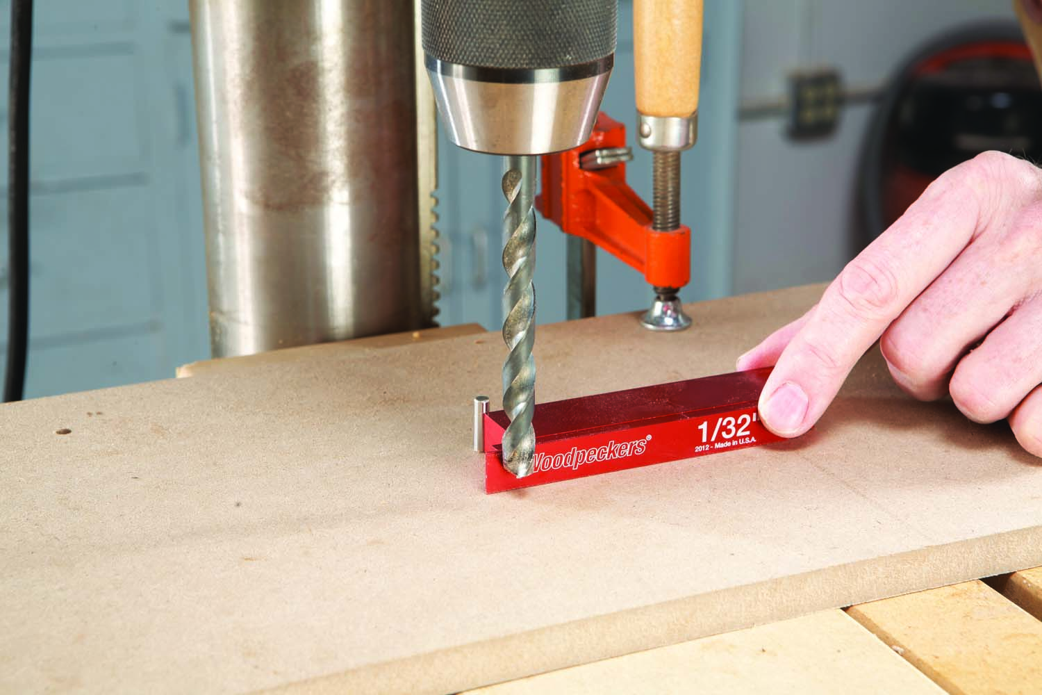
Photo 10. Set up a drilling jig with a group of setup blocks or a single shop-made block.
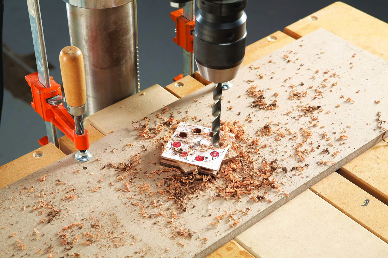
Photo 11. Rotate the blank on the jig and drill. Align the bit in each hole’s center by eye.
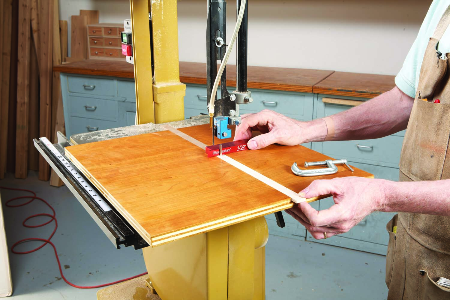
Photo 12. Set up a circle-cutting jig on the bandsaw. Use a 1/8″ blade.
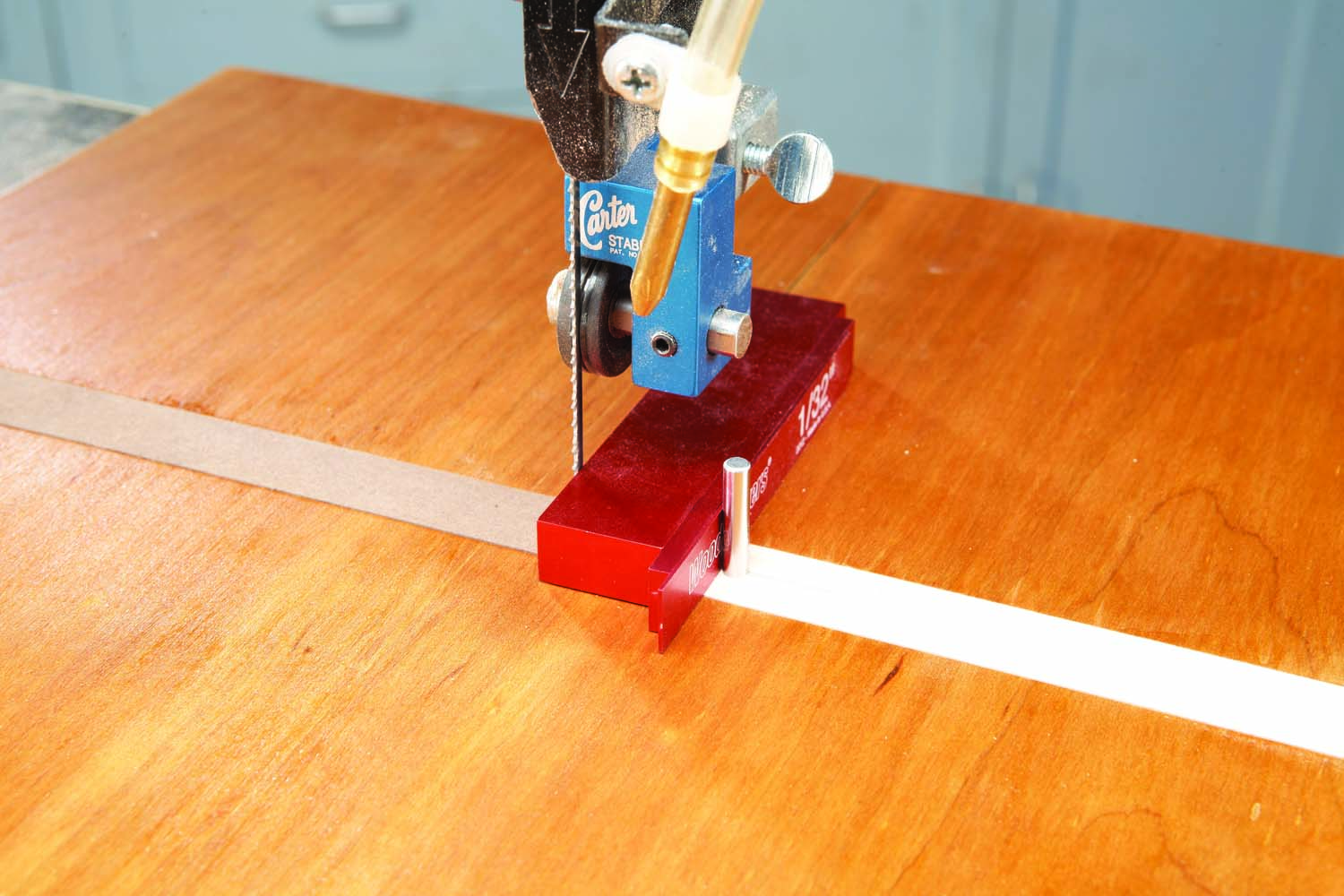
Photo 13. Position the jig’s pivot pin with setup blocks or a shop-made block.
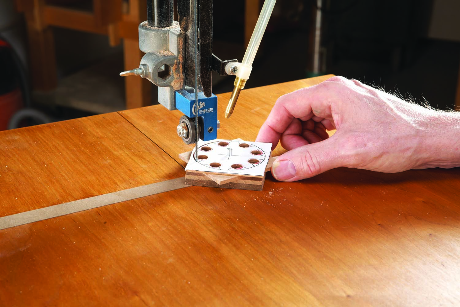
Photo 14. Place the gear on the pivot pin and push the jig into the blade. Rotate the gear.
Cut out the gear (the “addendum circle”) freehand or use a circle-cutting jig (Photos 12-14). Remove the backer board (Photo 15). Make a mandrel from hardware store parts, then sand the gear with sandpaper adhered to a tall, wide block (Photo 16).
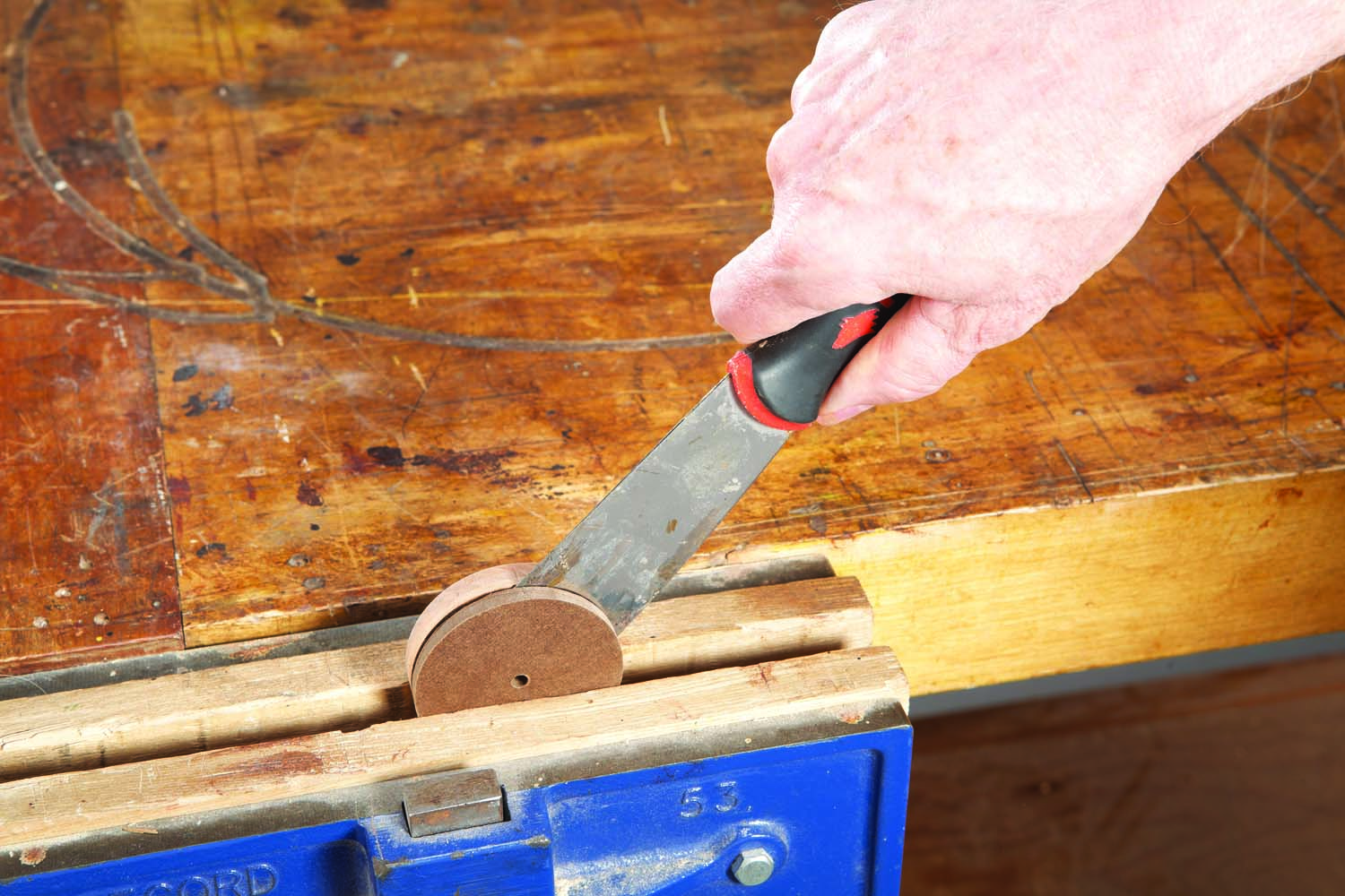
Photo 15. Pry off the backer piece. It prevented the gear’s bottom from having tearout.
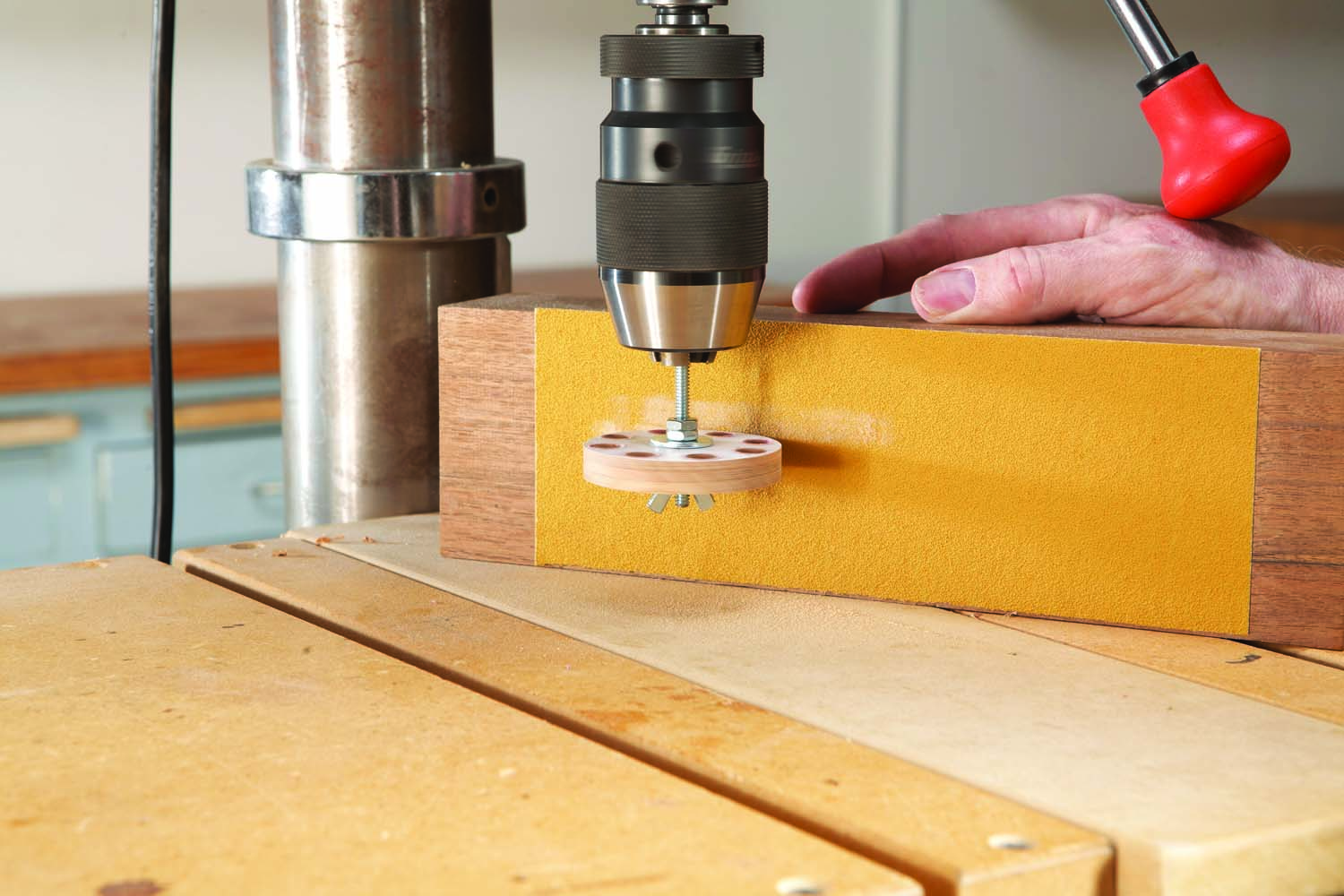
Photo 16. Sand away the saw marks. Make the mandrel by sawing off the head of a bolt.
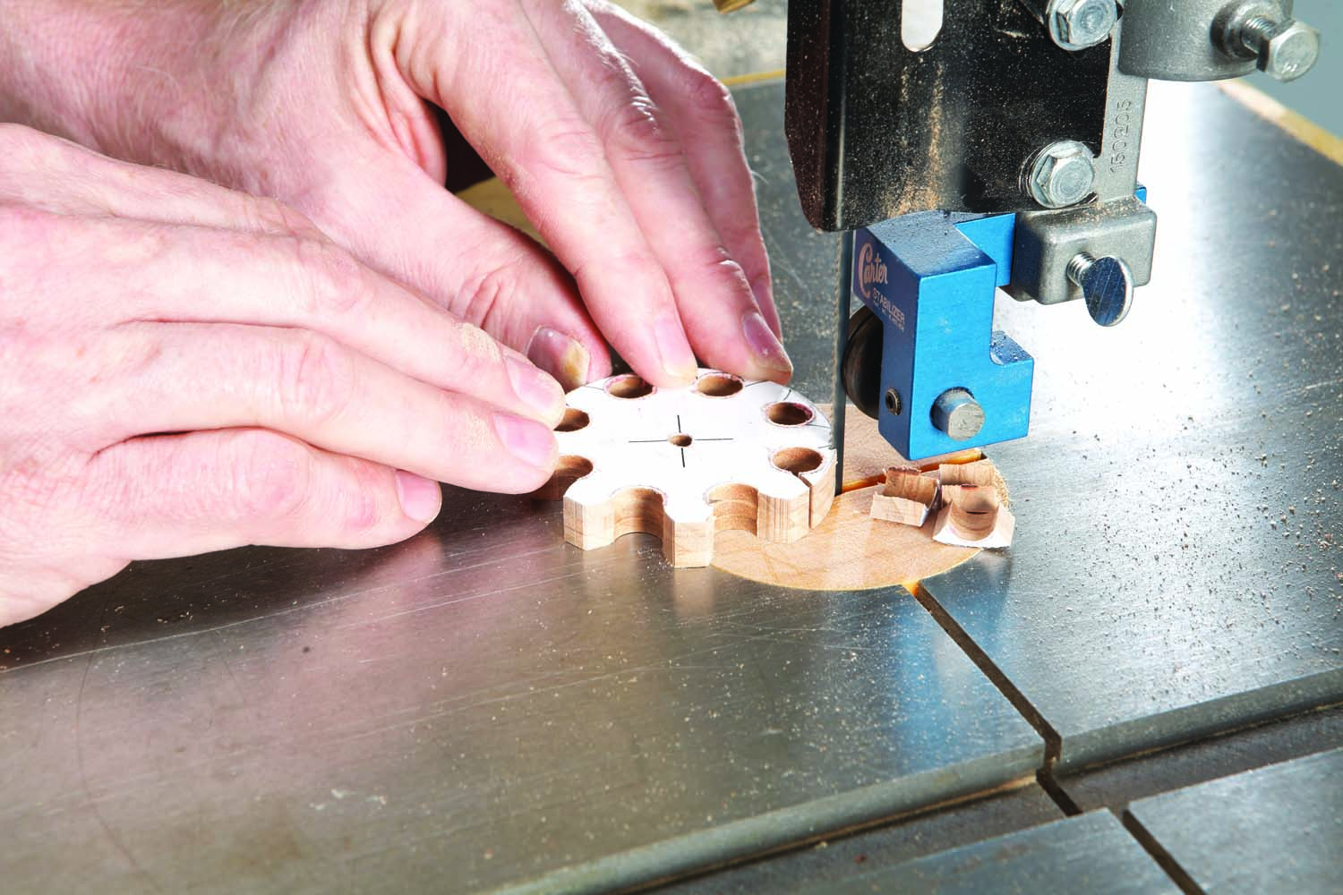
Photo 17. Saw out the teeth, following the pattern. Again, use a 1/8″ blade.
Saw the faces of the gear’s teeth (Photo 17). After cutting, use the side of the blade to lightly shave away any irregularities. Remove the pattern and clean up the gear (Photos 18 and 19). Glue the axles into the gears (Fig. 03).
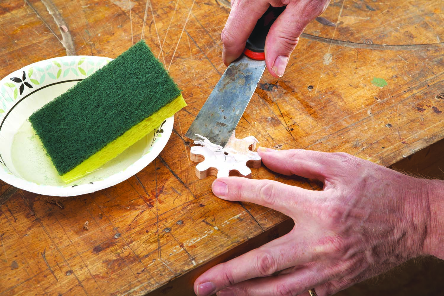
Photo 18. Wet the pattern and scrape it off. The paper had absorbed most of the glue.
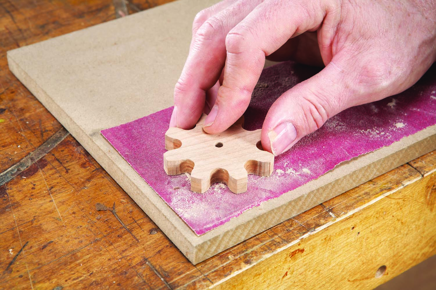
Photo 19. Sand both sides. Smooth the faces of the teeth with a file or sandpaper.
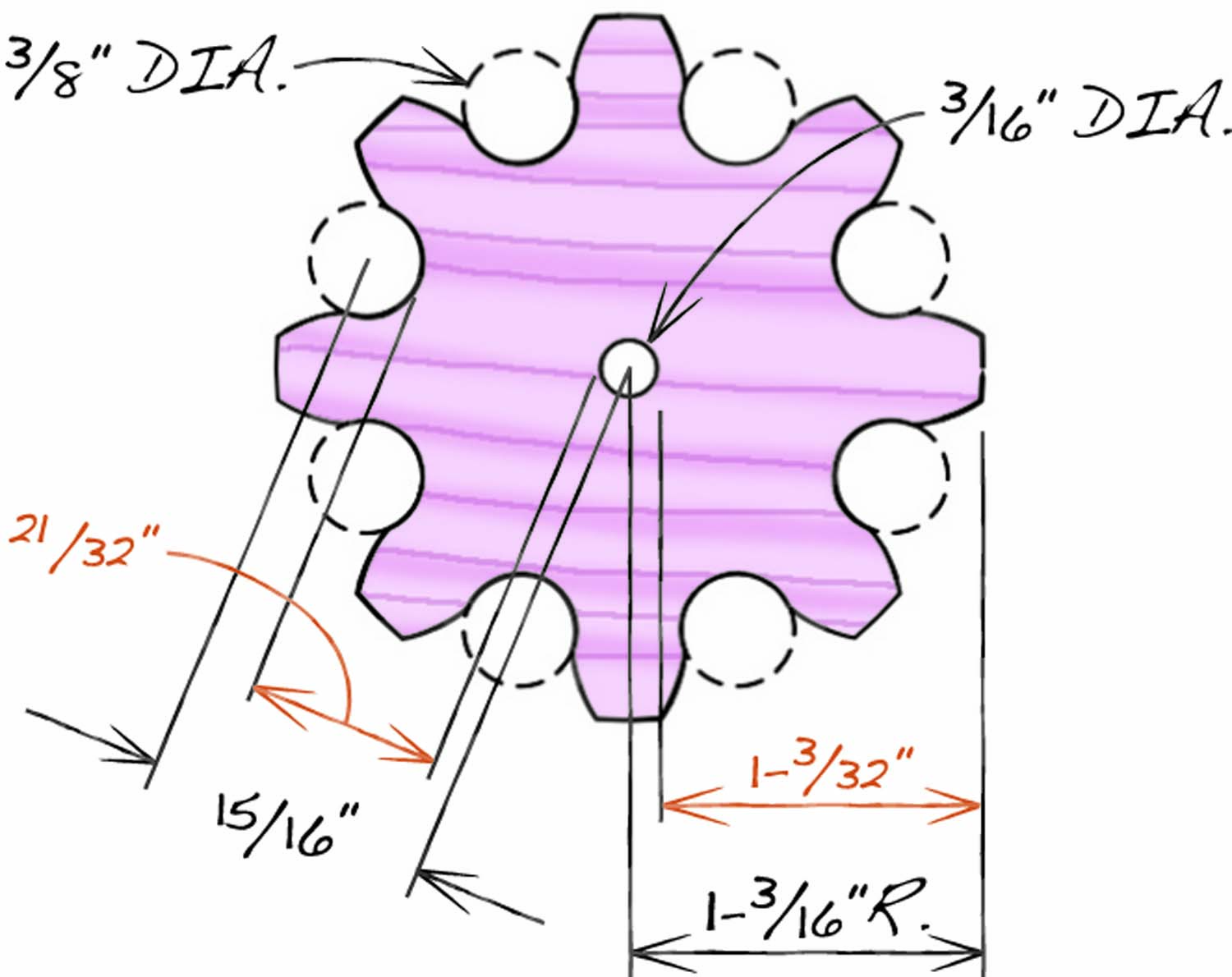
Fig. 06. Follower Gear Pattern
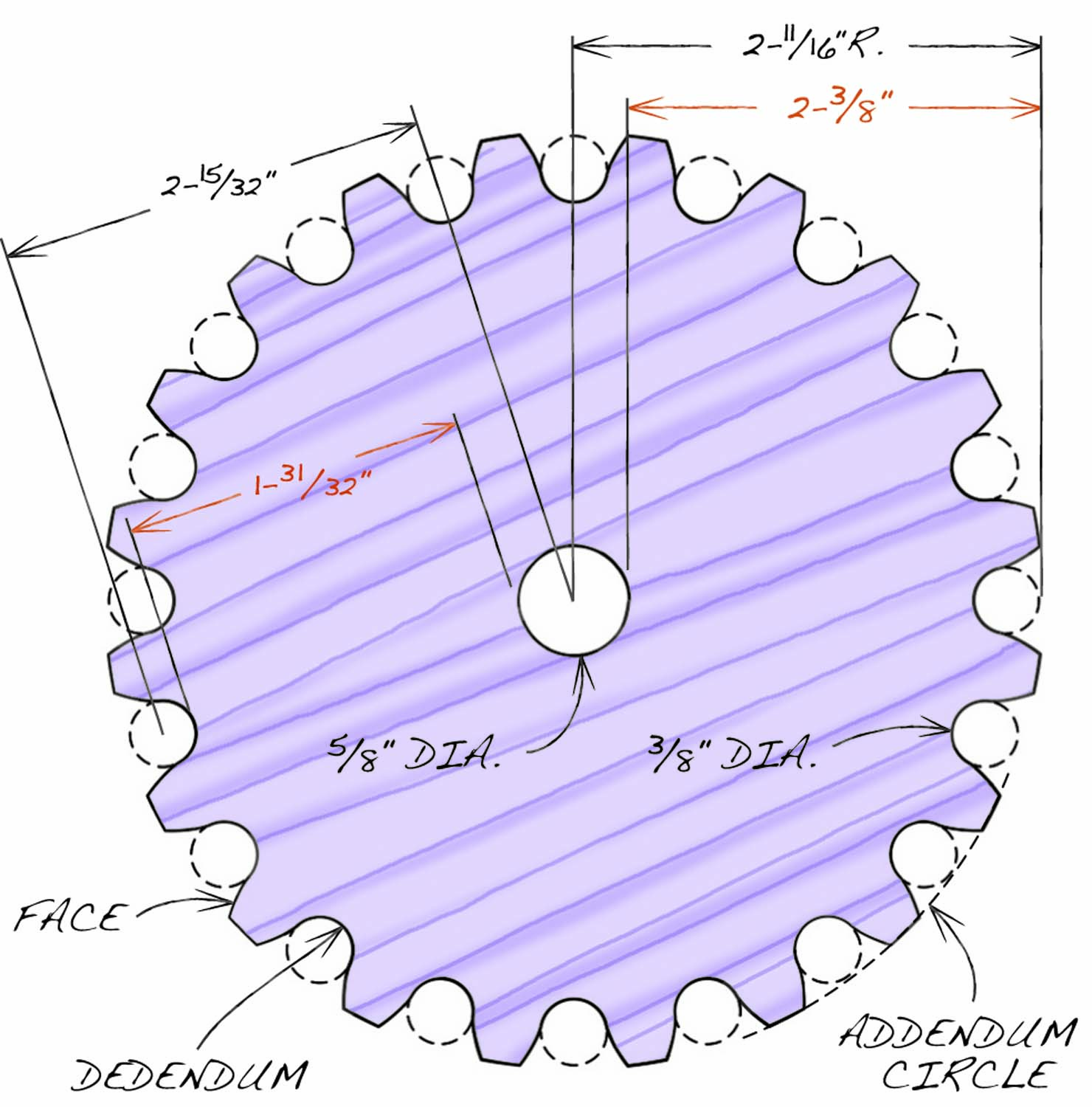
Fig. 07. Driver Gear Pattern
How to Make a Plate
The box’s skeleton consists of three almost-identical plates (A), six columns (B) and six spacers (C). The columns and spacers are simply dowels that are glued into one plate and screwed into another, so the box can easily be disassembled for fine tuning. The plates are glued up from segments. (If they were made from a single piece of wood, the distances between the holes would vary unequally as the wood moved.) Let’s look at how to make a typical plate.
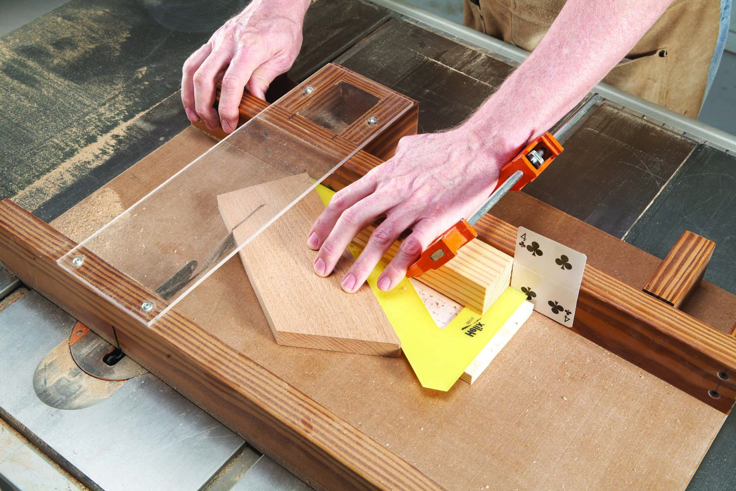
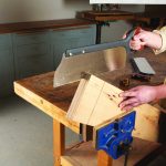
Photo 20. Saw 60° angles on both ends of three blanks. Crosscut the blanks in half.
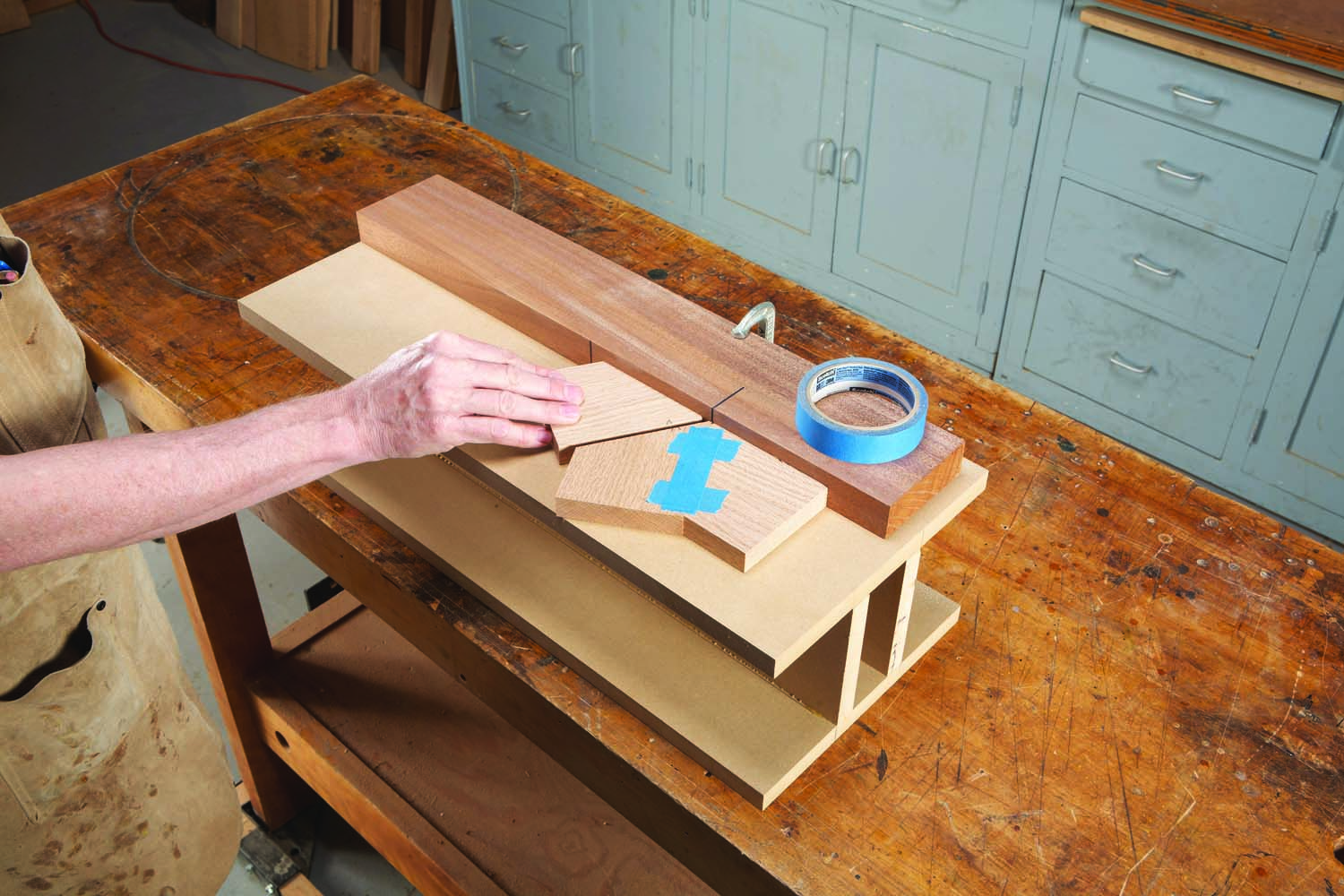
Photo 21. Tape three half-pieces together. Flip open the joints and apply glue.
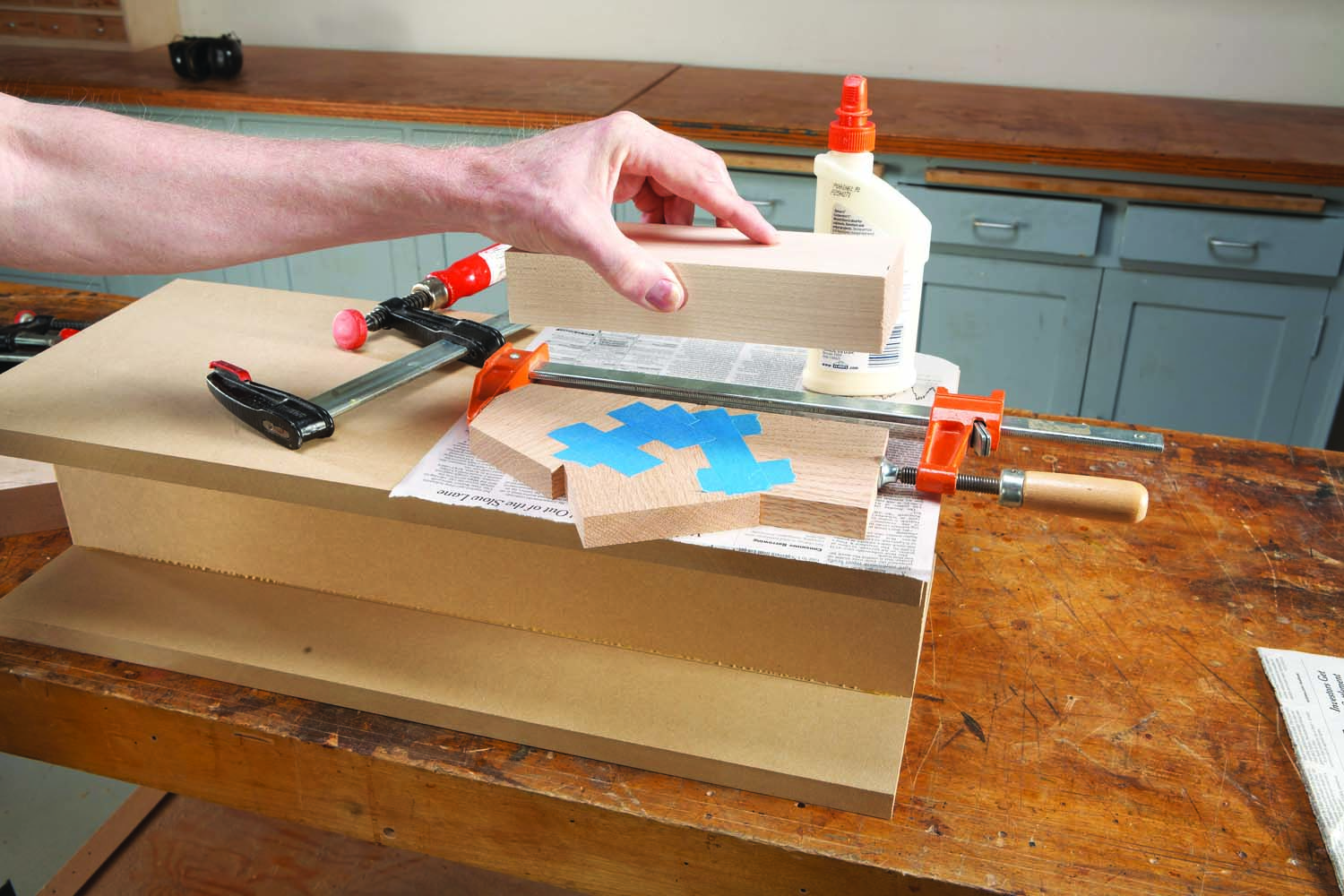
Photo 22. Clamp lightly across the joints, then clamp the assembly flat using a caul.
Mill three blanks for each plate (Fig. 08). Cut 60° angles on their ends by any means that’s safe and accurate (Photo 20). Crosscut each blank in half. Use a straightedge to align three of the pieces, then tape, glue and clamp them together (Photos 21 and 22). Repeat with another set of three pieces and glue the two assemblies together (Photos 23 and 24). Using cauls and a flat work surface for each step will produce a plate requiring very little leveling (Photo 25).
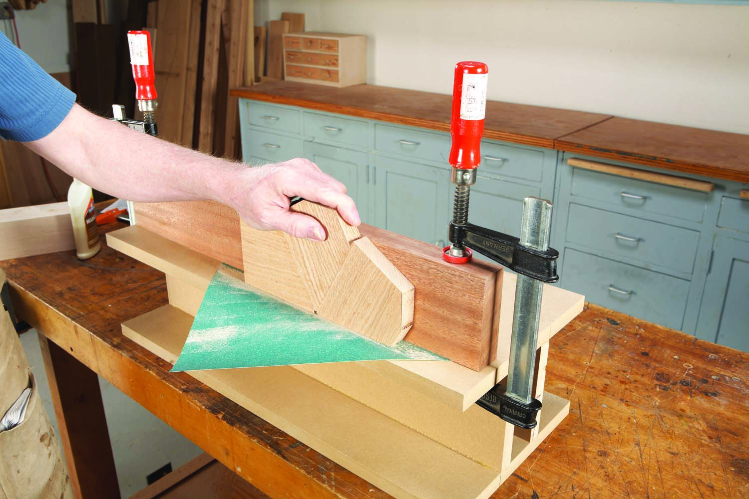
Photo 23. Joint the glue-up on 80-grit sandpaper, if necessary.
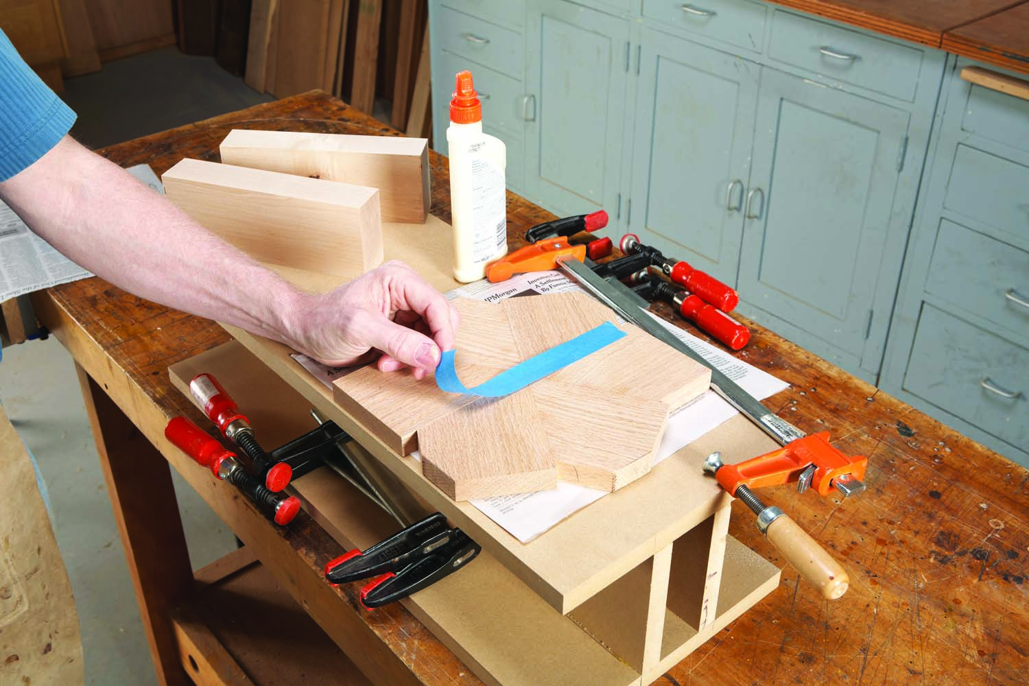
Photo 24. Tape two assemblies together and glue. Apply clamp pressure across and down.
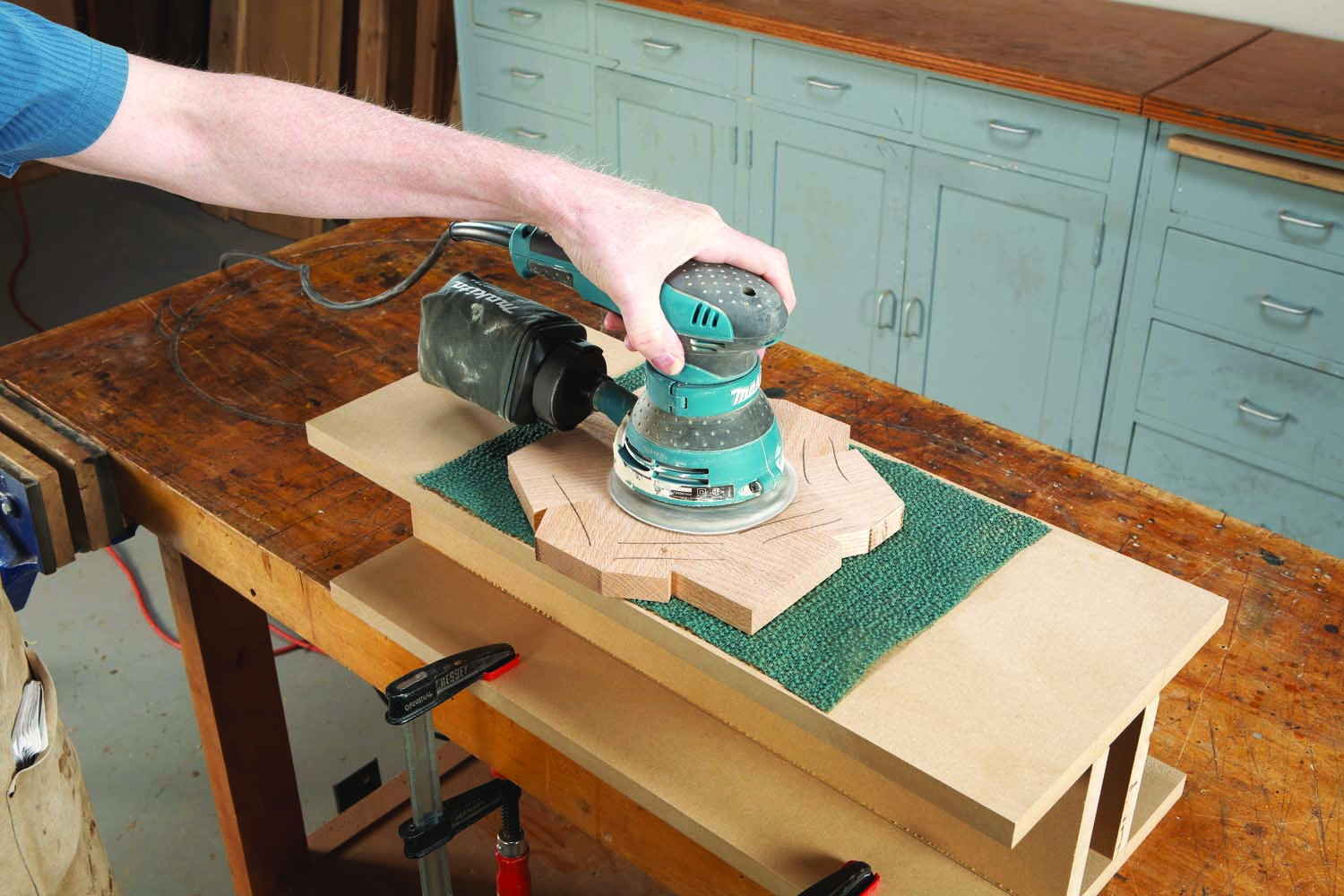
Photo 25. Sand both surfaces flat and even.
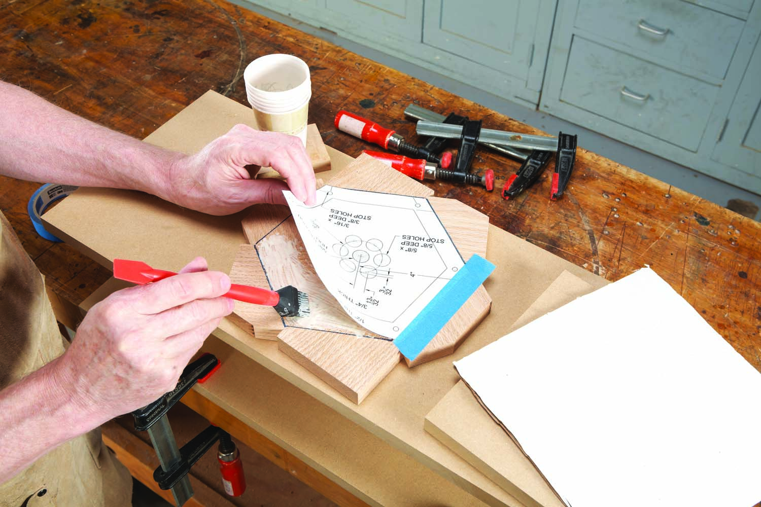
Photo 26. Glue on the plate’s pattern. Lay paper and a plywood caul on top, then clamp.
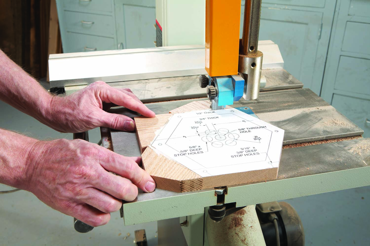
Photo 27. Follow the edges of the pattern to saw the plate into an octagon.
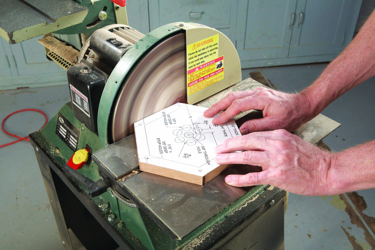
Photo 28. Straighten and smooth the edges by sanding.
Glue on the pattern and saw the plate into a hexagonal shape (Photos 26-28). Use the gear-drilling jig (with a larger pivot pin) for drilling holes (Photo 29). Rabbet the top and middle plates (Photo 30).
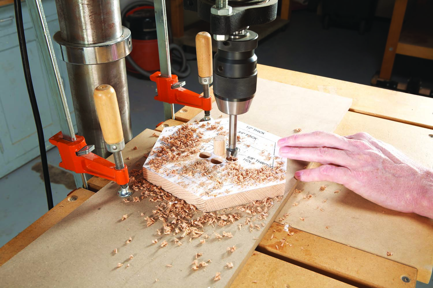
Photo 29. Drill the plate’s holes using the pivot-pin method employed for the gears.
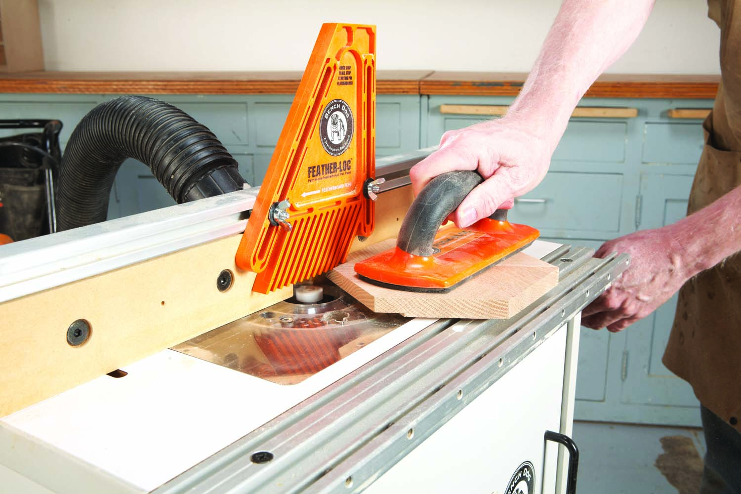
Photo 30. Rout a rabbet around two plates using a large-diameter hinge-mortising bit.
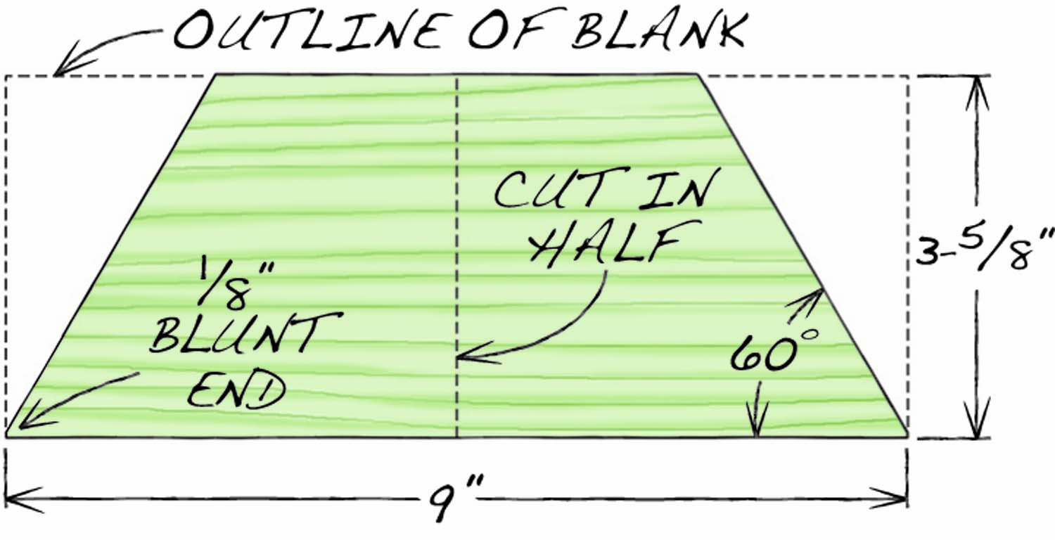
Fig. 08. Plate Segment Blank
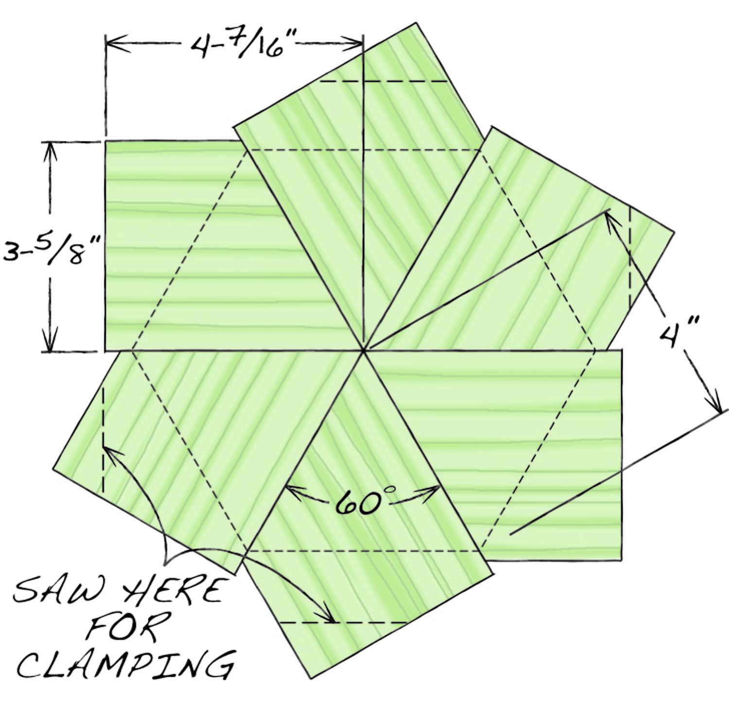
Fig. 09. Plate Glue-Up
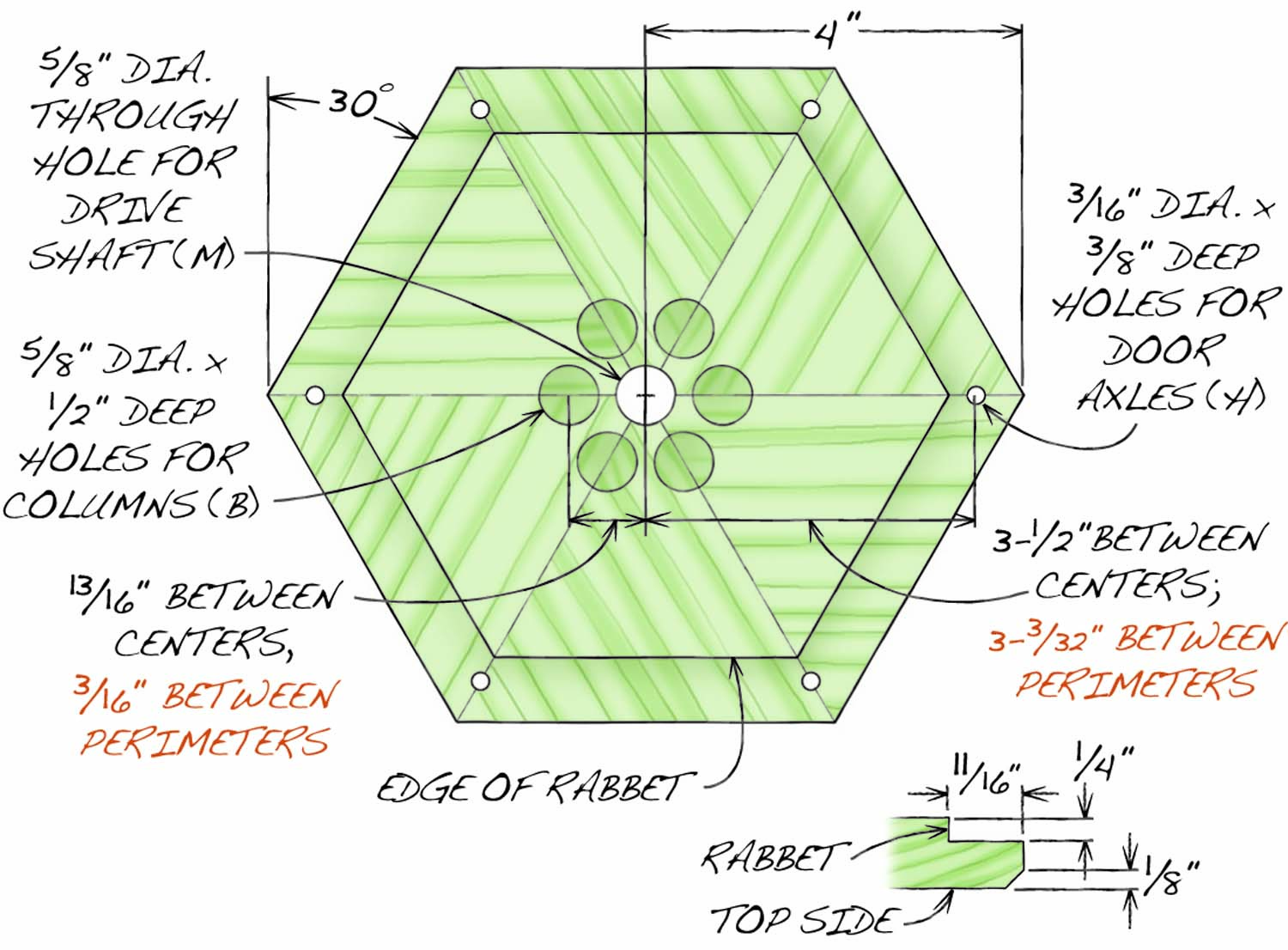
Fig. 10. Top Plate Drilling Diagram, Viewed from Bottom
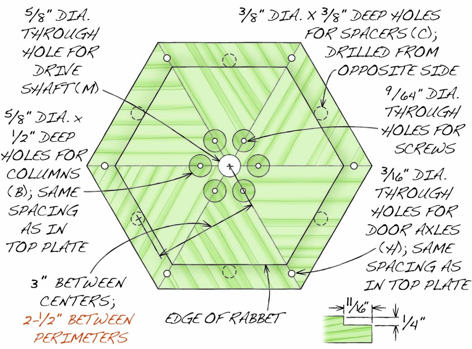
Fig. 11. Middle Plate Drilling Diagram, Viewed from Bottom
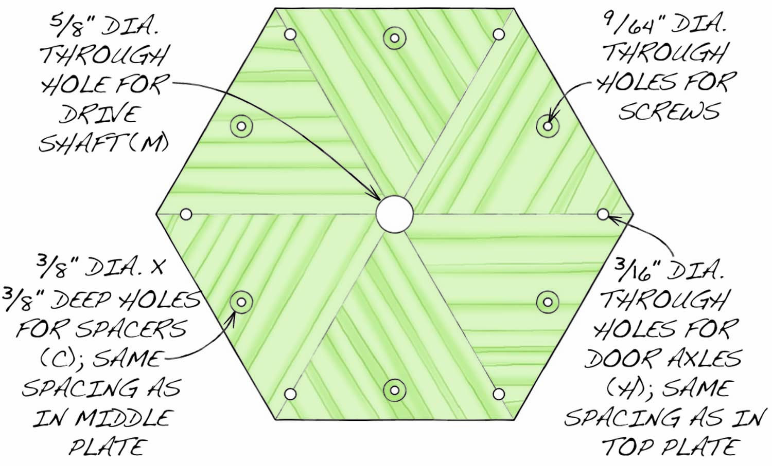
Fig. 12. Bottom Plate Drilling Diagram, Viewed from Top
Here are some supplies and tools we find essential in our everyday work around the shop. We may receive a commission from sales referred by our links; however, we have carefully selected these products for their usefulness and quality.