We may receive a commission when you use our affiliate links. However, this does not impact our recommendations.
Add GFRC to your furniture-making arsenal.
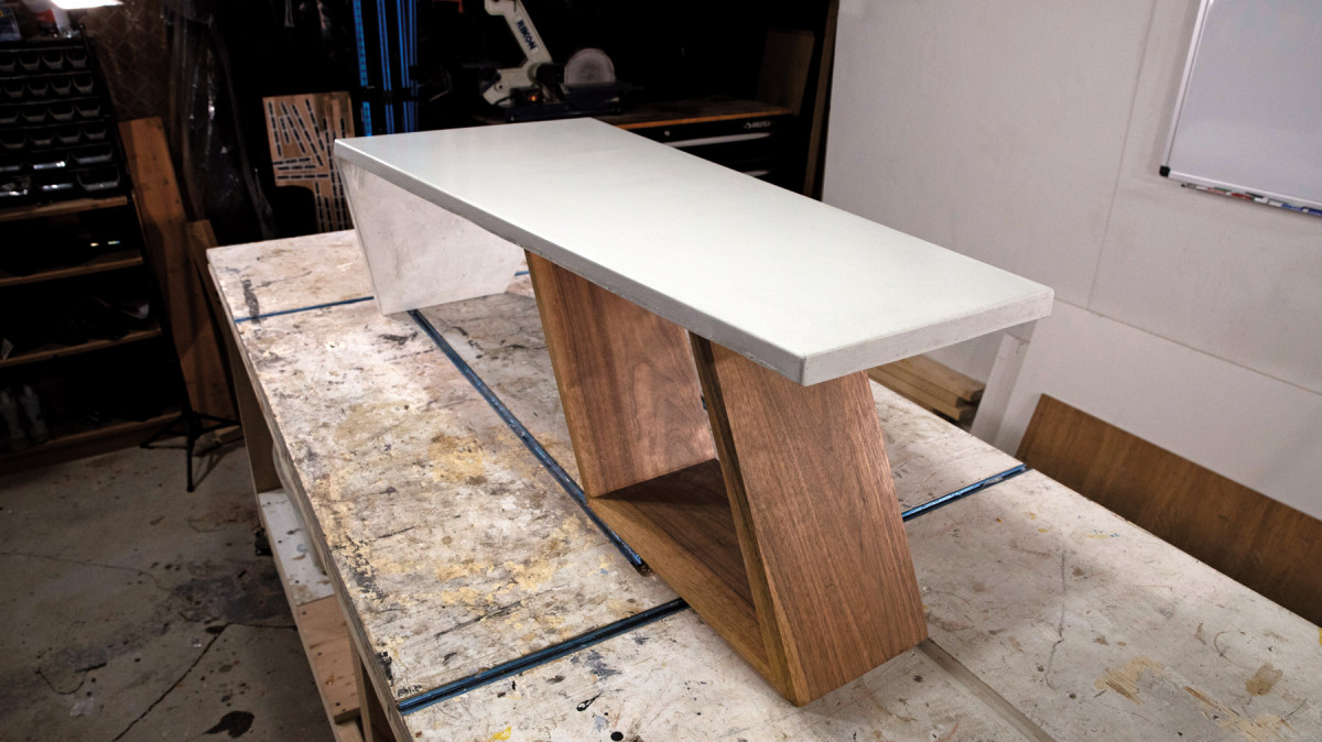
I’ve always loved aircraft-inspired design. There’s just something about an everyday item inspired by a plane that evokes a sense of wanderlust in me, and I wanted to make a piece of furniture that had that aircraft feel. This concrete and walnut “wing” table is the result.
Before I go further, let me answer the questions on everyone’s mind: Why concrete? Isn’t this a woodworking magazine? If you’re a woodworker, you already possess many of the skills and tools needed to work with concrete. And, adding concrete to your design arsenal will open a world of new design possibilities.
For this design, concrete was the perfect choice. And it’s not just any concrete, it’s white glass-fiber reinforced concrete (GFRC). Standard concrete mixes from the big-box store must be cast 1 1/2” to 2″ thick, while a GFRC mix can be cast as thin as ¾”. Glass fibers are embedded in the mix, and when cured, give it more strength than a typical aggregate-only concrete mix. GFRC allowed me to achieve the sleek, modern, aircraft-inspired aesthetic I was looking for by casting the angled waterfall tabletop as a single 1″-thick piece.
Building the Form
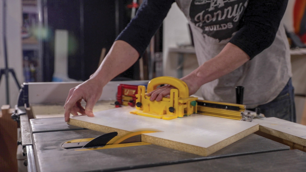
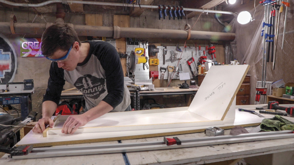
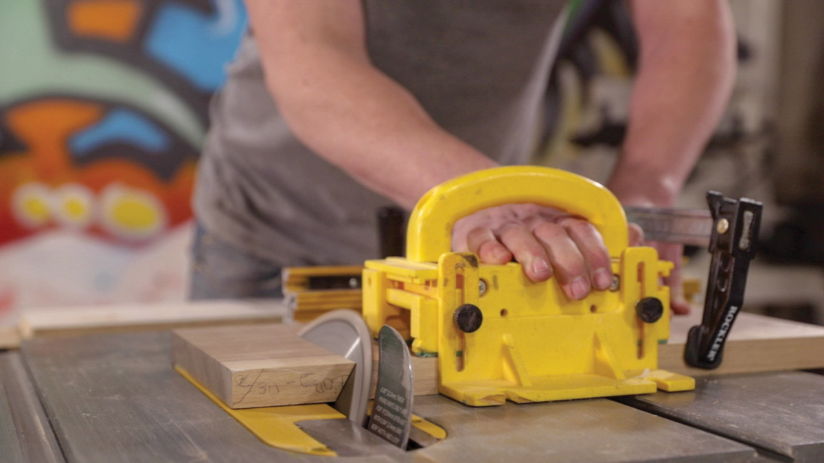
1. Cutting 30° support pieces for the waterfall base with a miter gauge on the table saw.
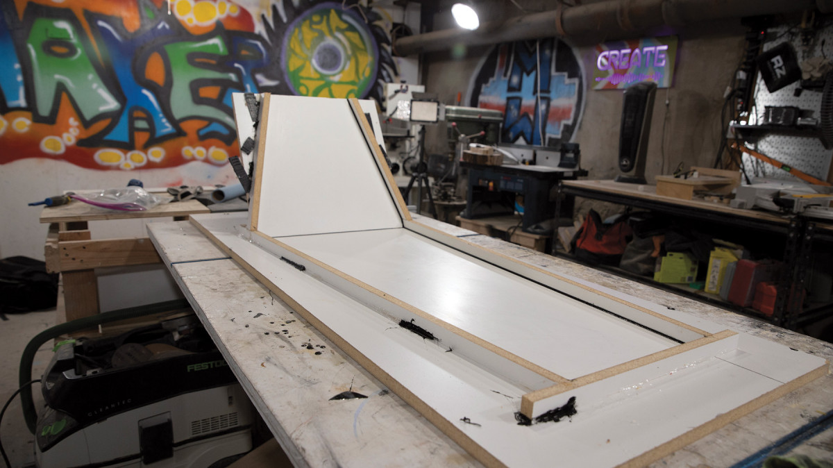
The first step in most “precast” concrete projects is building the form into which you’ll spray and/or pour the concrete. The form is essentially an upside-down, reverse image of the piece you’re making. Many materials can be used to make a concrete form. However, melamine is the most popular material, since concrete doesn’t stick to its smooth waterproof surface, and it’s easy to cut and shape with standard woodworking equipment.
2. Using hot glue to build up the concrete form before screwing things together.
There are two approaches to building the melamine form. The first approach is cutting the base of the form to the exact shape of your final piece and then screwing the sides of the form to the sides of the base. The second approach is using a sheet of melamine as a base, and gluing the edges of the form on top of the base in the desired shape. I use the first approach when creating simple rectangular slabs, but find the second approach much easier for projects with complex shapes (like this one). It allows you to sketch the desired shape directly onto the melamine base with a dry-erase marker, and then cut the side pieces to fit as you lay them out around the sketch.
3. Attaching the side pieces of the form.
To make the form for my table, I cut two rectangular base pieces, with the larger one being a bit longer than the length of the table (including the angled waterfall), and both being wider than the sides of the table by a few inches.
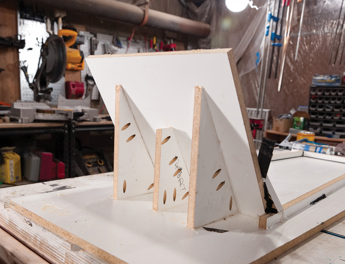
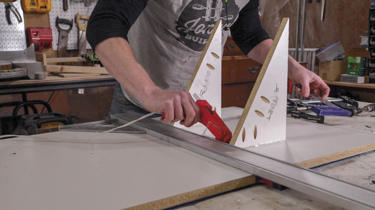
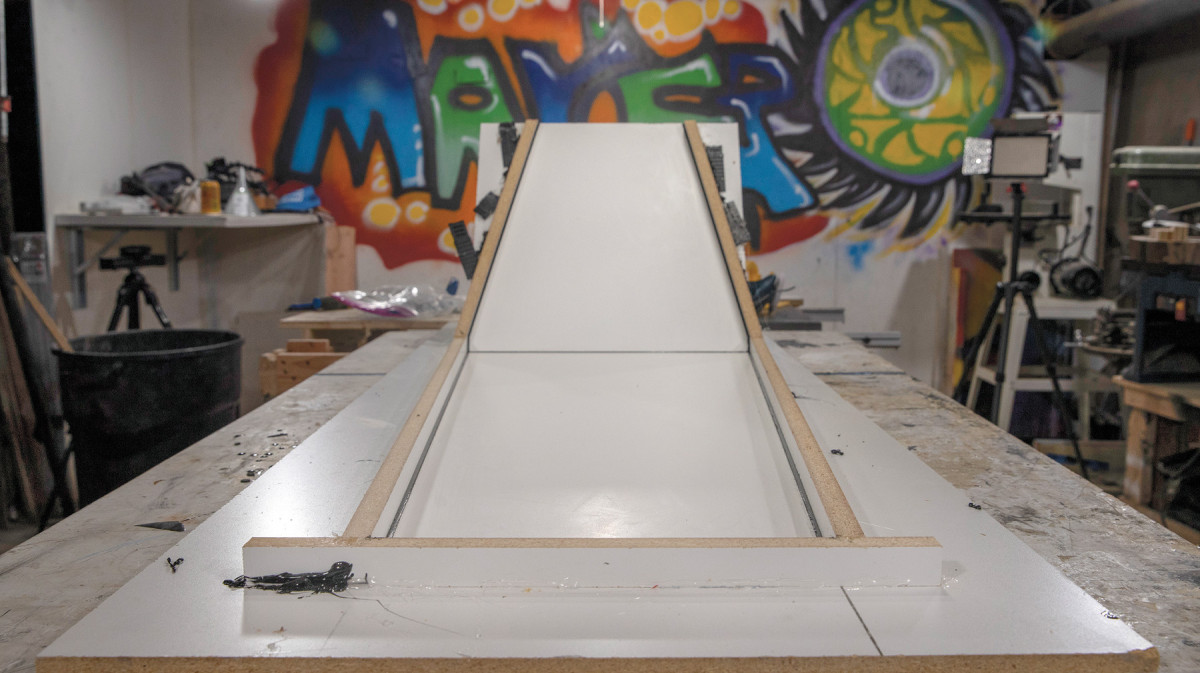
4. The form has to support the weight of the concrete waterfall.
The waterfall base needs to support the weight of the concrete during the pour, so I cut triangular support pieces from scrap melamine. The support pieces don’t need to be pretty, so pocket holes work well to secure the support pieces to the base. However, melamine is slippery and the support pieces have to be aligned such that the two bases provide a perfect tabletop-to-leg transition. As such, I aligned the triangular supports using a straight edge and hot glued them to the base before I screwed them to the base. I could then clamp the waterfall base against the supports and secure it using hot glue and screws.
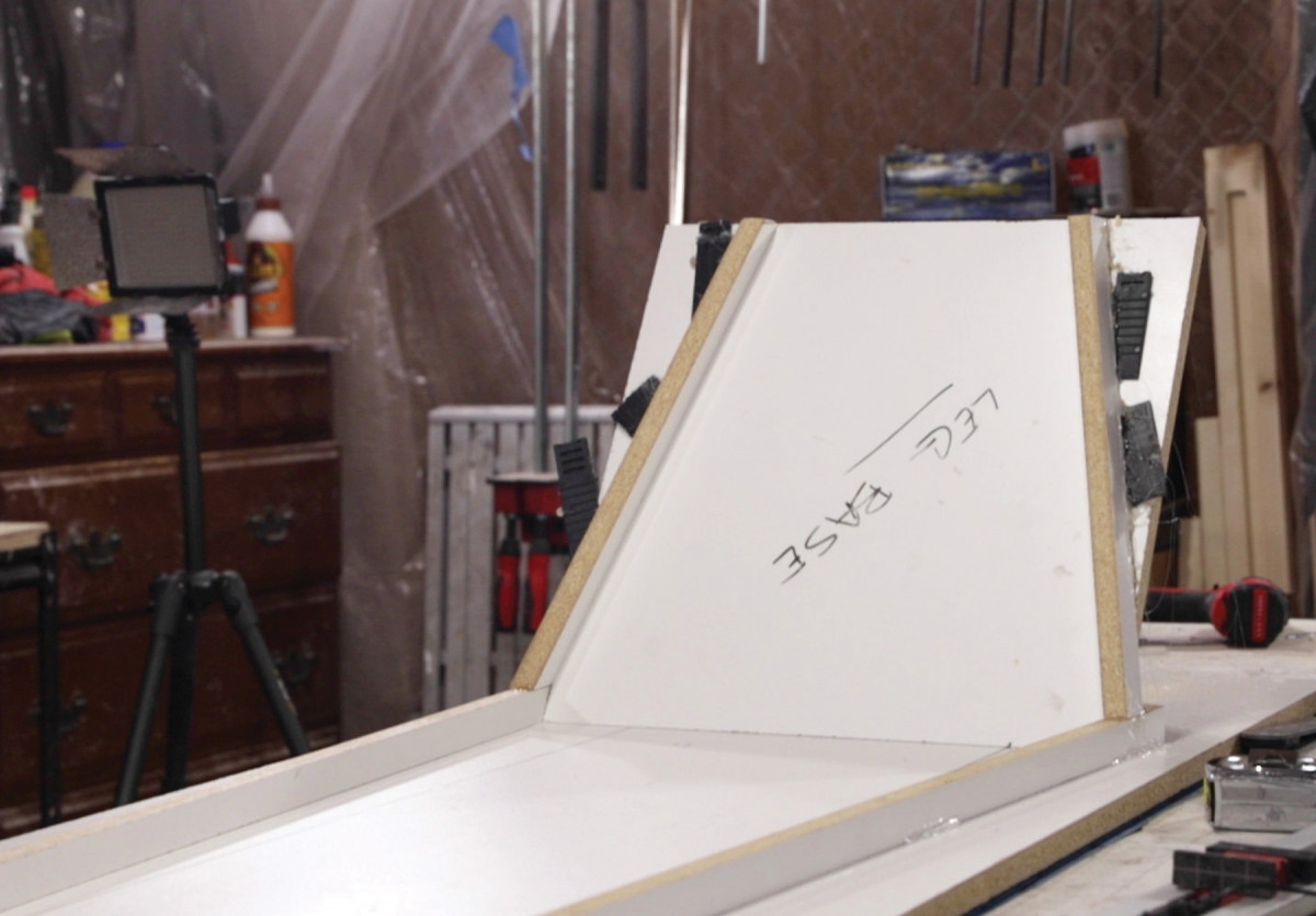
5. The sides of the waterfall form were shimmed in lieu of a complicated triple miter cut.
Pieces of the form that won’t bear significant weight can often be joined using only hot glue on exterior seams, which greatly simplifies the process. Also, you’ll be much more efficient if you can let go of the woodworker’s desire for perfect joints. Small gaps and misalignments at interior joints will be filled with silicone caulk when you seal the form, so they won’t affect the final concrete product.
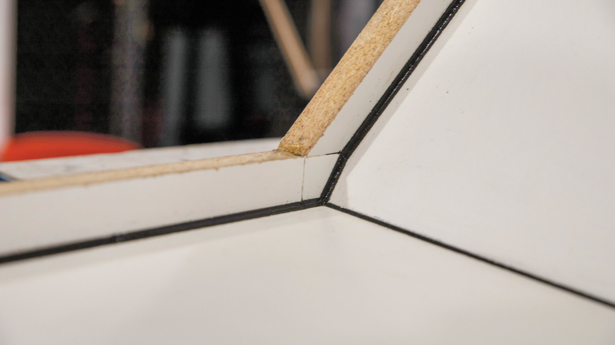
6. As long as the inside corners align, the outside of the form can be a mess.
Before cutting the sides for the form, I use a dry-erase marker to sketch the angular “wing” shape on the base of the form. I ripped 1″ strips of melamine on my table, and used my miter saw to cut the side pieces to fit from the 1” strips. The side pieces were placed on the base of the form (using the sketch as a guide), and secured to the base using hot glue at exterior seams.
Compound Angles
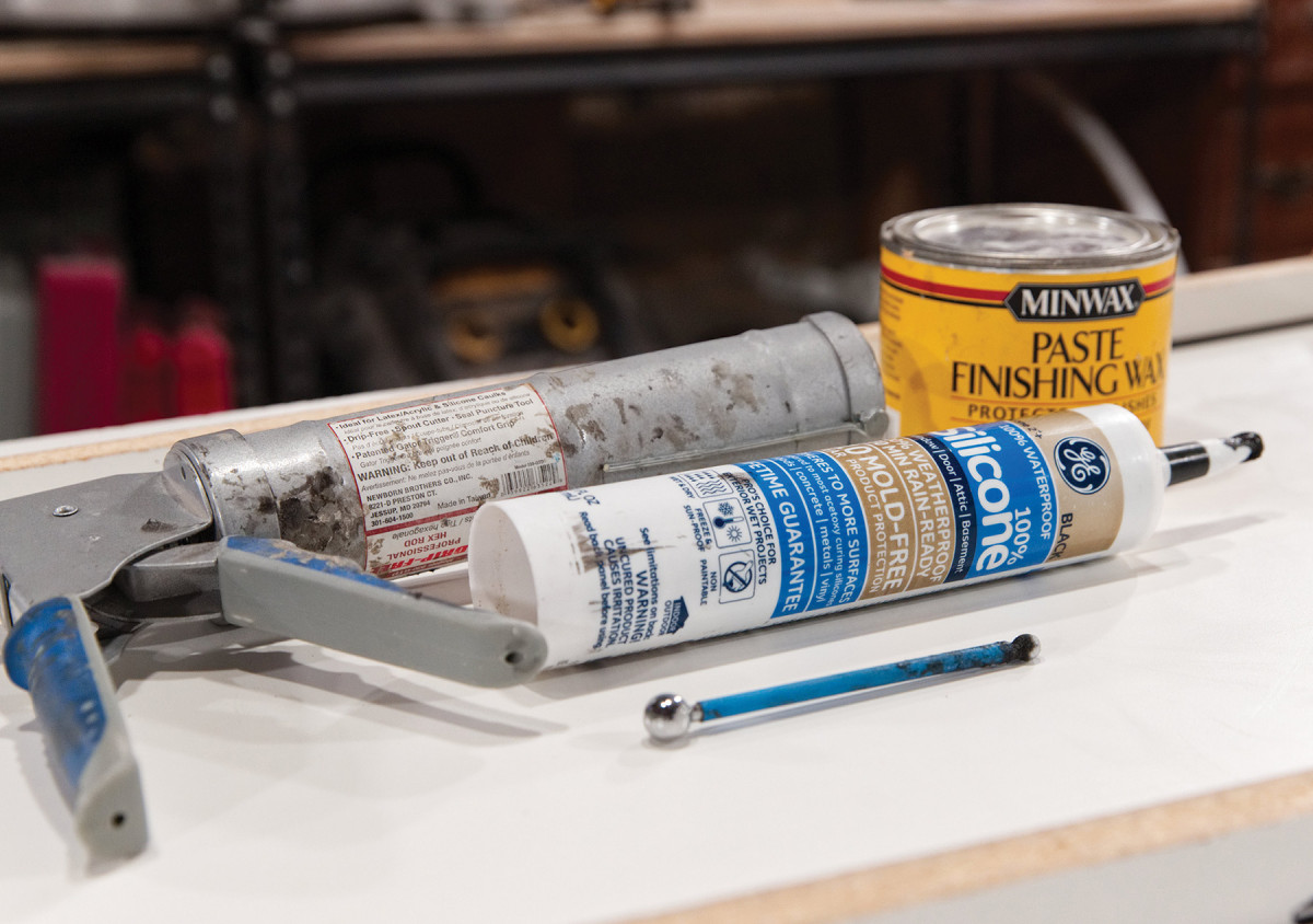
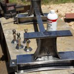
7. For perfect caulk lines: a caulk gun, paste wax, 100% silicone caulk and a fondant ball tool.
The sides of the waterfall form were a bit tricky. If you’re like me, compound miter joints make your head spin. To cut the sides perfectly, you’d need to cut a triple compound miter joint to account for the inward angles of the waterfall and top, as well as the 15° outward slant of the waterfall. However, if you let go of your woodworking instinct and remember it doesn’t matter how the outside of the form looks, it simplifies things.
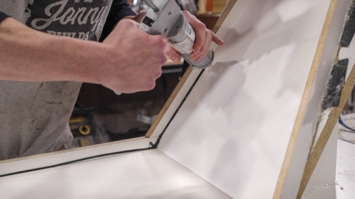
8. After applying paste wax to the form, a bead of caulk is applied.
I cut a double miter at 15° backward and 4.5° inward (to match the outward and inward angle of the waterfall, respectively). To attach each side piece, I used one hand to hold the side so it tilted inward off the waterfall base, and the inside seams were flush with the tabletop side pieces, and used my other hand to shoot a few dabs of hot glue under the gap under the exterior edge of the side piece that results when the side is held in this position. I could then use shims and more hot glue to fill the exterior gap, so that it wouldn’t give way during the pour. The outside of the form isn’t pretty, but it doesn’t need to be!
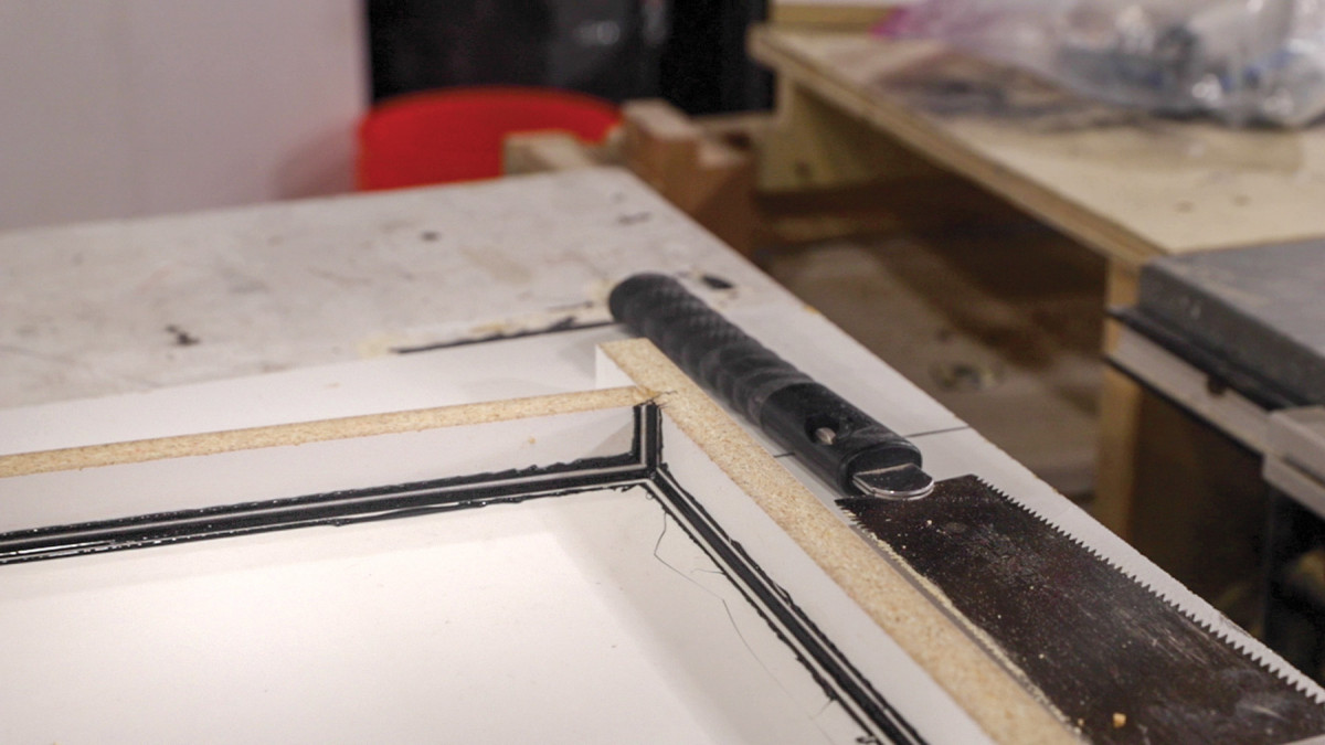
9. Immediately after caulking, running a fondant ball tool over all the seams squeezes out excess caulk.
Note that I left the waterfall side pieces a bit long when attaching them, instead of trying to cut them to the perfect length (and at the perfect angle). This way, once the waterfall sides were attached, I could come back with a flush-cut saw and use the base of the form as a guide to cut them perfectly flush and straight.
Sealing the Form
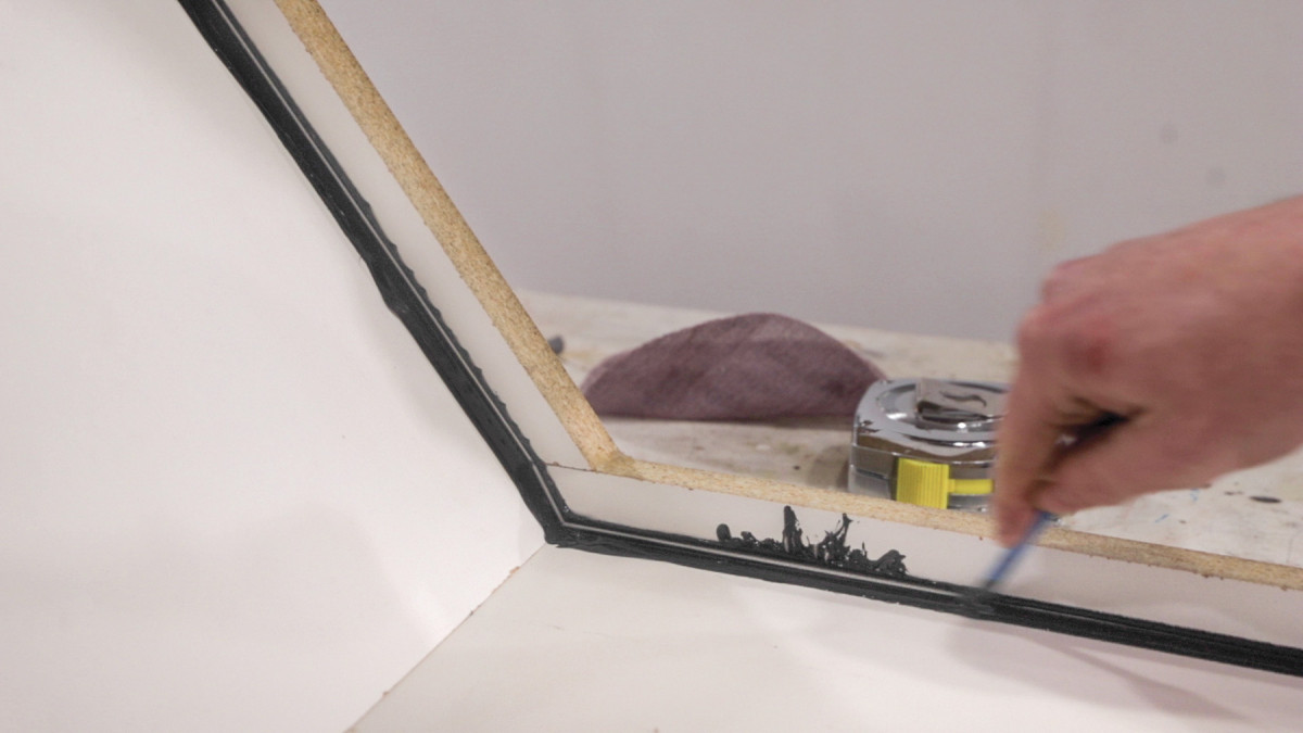
10. An almost-perfect caulk line.
After building the form, it’s time to seal it with 100% silicone caulk. I use black caulk so it’s easier to see (and correct) flaws in your caulk line—a must since the final concrete piece shows every detail of your form. Before caulking, I apply a layer of paste wax to the inside surfaces.
11-12. Once the caulk has cured, you can trim away the excess.
I then apply a generous bead of caulk along all seams. Immediately after applying the caulk, I come back and run a metal ball tool over the caulk lines. (This tool is also referred to as a fondant tool, and is commonly used to decorate cakes.)
 The metal ball pushes excess caulk away from the seam, leaving a perfect line in the middle. The paste wax applied before caulking allows the squeeze out to be pealed away easily after the caulk cures, leaving perfect caulk lines.
Concrete Time
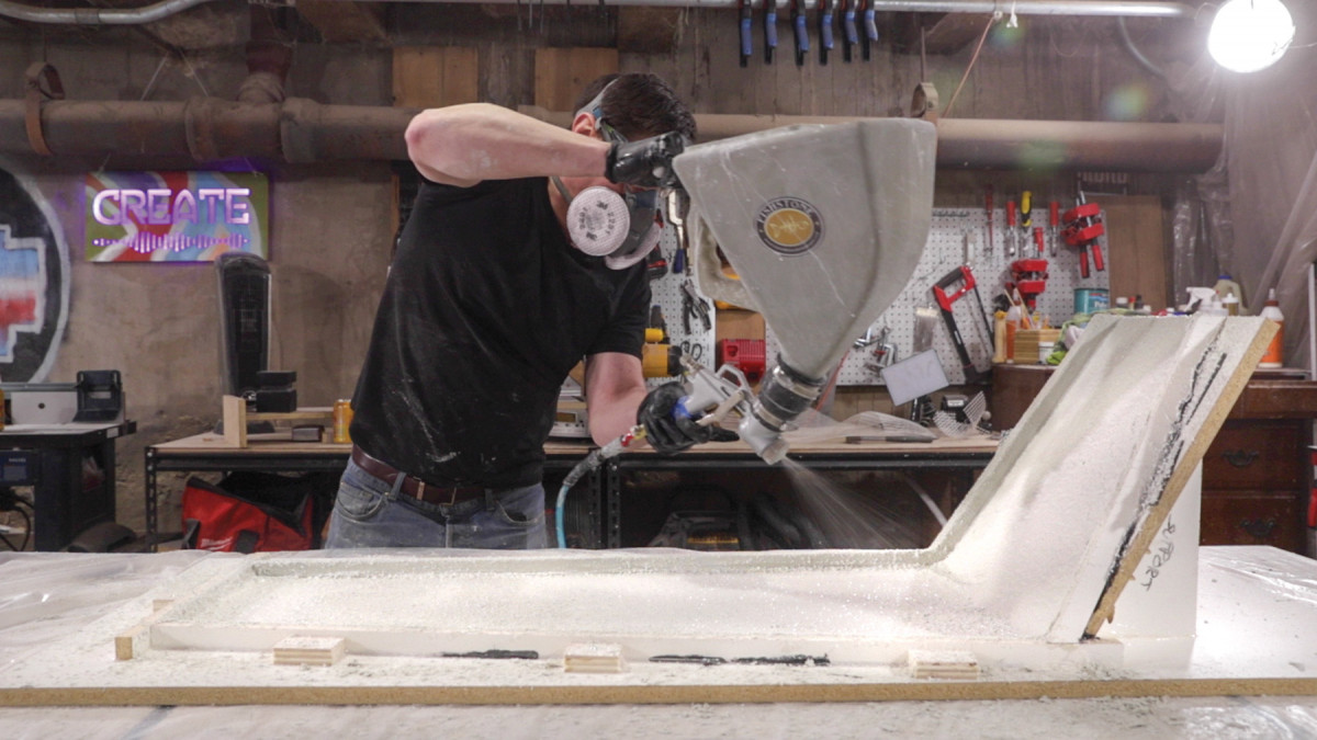
13. The first step in the concrete application process is spraying a coat of the concrete. Then, you’ll pack the form with the glass fiber and concrete mixture.
Now for the fun part: the concrete. To get a smoother surface right out of the form, I used a two-part process where the form is first sprayed with a thin layer of GFRC mix without any glass fibers, before applying backer layers of GFRC mix with the glass fibers. The sprayed layer is often referred to as the face or beauty coat. It’s applied using a drywall hopper gun powered by an air compressor. Since the largest aggregate in the GFRC mix is #30-grit sand, spraying a thin (1/8“–1/4” layer) coat and then brushing it into the nooks and crannies of the form, produces an ultra-smooth surface with very few pinholes (compared to a typical concrete mix).
After spraying the face coat, I quickly (within seconds) use a chip brush to work the mix into the seams, and brush the entire surface lightly. Brushing the surface pops any air bubbles that might be trapped against the form, further reducing the chance of pinholes. I sprayed a second face coat after the first one firmed up, although the second coat is optional.
14. The form is packed in multiple steps. It’s not an exact science–the way the material behaves depends not only on the amount of water in the mix, but also the conditions in your shop.
The GFRC backer layer consists of the same GFRC mix as the beauty coat and includes alkali resistant (AR) glass fibers. (AR fibers shouldn’t be confused with run-of-the-mill fiberglass, which would break down quickly due to the alkalinity of concrete.) The timing of the backer coat is important. You need to wait until the face coat is firm to the touch, but still wet, so the backer coat will stick to it.
Since this table is 1″ thick, and my face coat was 1/8“, I measured out buckets of mix (by volume) to do two back layers of slightly less than 1/2” each. And, since this form has a large vertical surface (the leg), I decided to use AR glass mesh (a mesh sheet of the same AR glass the fibers are made from), in addition to the AR glass fibers in the mix itself, to support the structure. The scrim will be placed between back-coat layers and provides extra strength. It also reduces the chances of the concrete slumping as the vertical parts of the form are packed in. I cut a single piece of AR mesh to fit the form shape, and then moved on to mixing the first backer coat.
Packing the Form
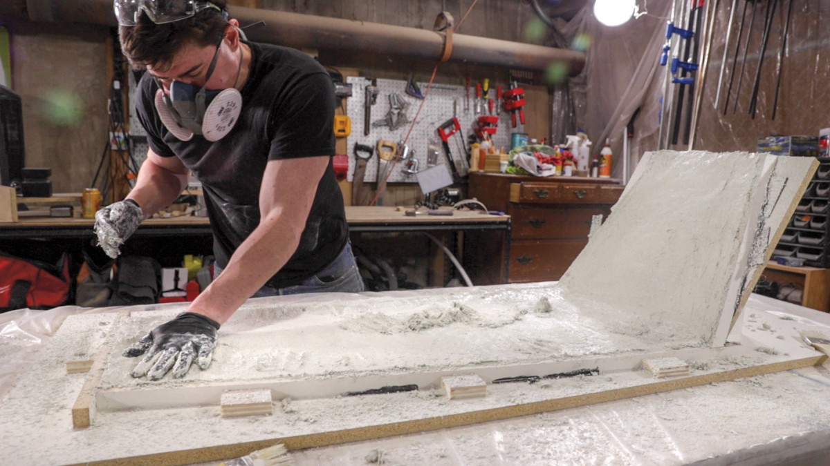
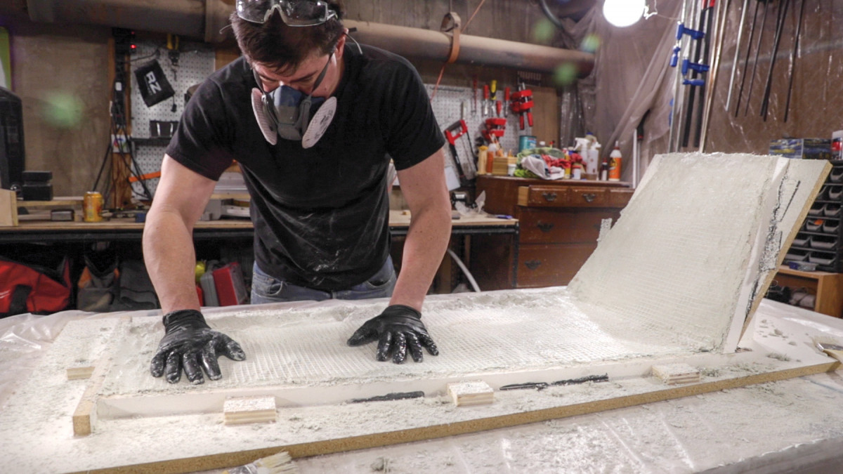
15. Getting the hang of packing the form happens pretty quickly. After the first layer is packed, you wait a bit for the concrete to set up so you can pack the second layer.
With the first backer coat mixed, it’s time to start packing the form. The concrete mix should have the consistency of slightly wet Play-Doh. It needs enough mass to hold its shape, but it should still be sticky enough to adhere to the previous coats. The directions on the bag of concrete mix give you a good starting point, but you may want to experiment a little if this is your first time using the material.
Packing the form is pretty straightforward. Pour a handful of the mix into the form, and use your hands to pack it in place. This first coat is going to be just under a 1/2” thick, so keep that in mind as you move through the form. Once you have the first layer in, wait for the concrete to cure. Depending on the conditions in your shop, this could take an hour or more. You’re not looking for a full cure, but just enough so the first concrete layer can support the second layer as you pack up the vertical leg surface. If it’s not cured enough, it’ll slump off the form, and it’s not fun (see sidebar on page 28).
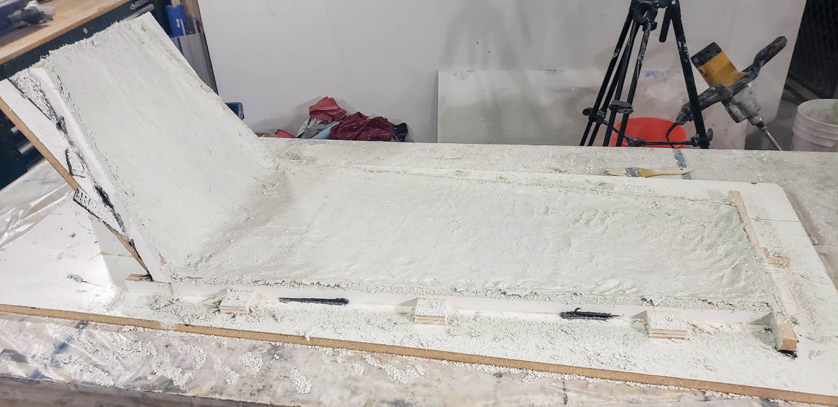
16. You might be tempted to try and smooth out the concrete once the form is packed, but it’s much easier to grind this flat after it’s cured.
Before you pack the second layer, make sure to place the sheet of AR mesh in the form. Then pack as you did the first layer until you’ve reached that 1″ thickness. You may be tempted to try and smooth or screed the final layer after it’s all packed, but the glass fibers in the concrete make that difficult. The glass fibers tend to catch on the screeding board, which makes it difficult to achieve a level surface, and can sometimes pull the face coat away from the edges of the form. It’s best to just leave it as is and smooth after it’s cured.
Practice Patience
During my build, the back coat didn’t go quite as planned. When hand-packing GFRC up a vertical surface, you want to pack in layers of 1/2” or less, allowing enough time for the previous backer layer to firm up before packing the next one. I was squeezed for time (with dinner plans), and the concrete started to slump as I added the second layer. I was able to save the project, but I’ll also be telling you what you should do to avoid some of the moments of panic I experienced.
I mixed the first backer coat, spreading it up the vertical surface by hand. It was going well. I then added the sheet of AR scrim I’d cut earlier and massaged it into the back coat. At this point, the vertical was packing nicely and not slumping, and I still had 31/2 hours before dinner. So I waited…and waited…and 2 hours later I realized my error. The temperature had dropped outside and my shop was now 65°. The cold greatly increases the cure time of concrete.
An hour and half before dinner, when the first backer layer still wasn’t firm enough, I realized I had to make a choice between rushing the project and upsetting my significant other. We all know this isn’t really a choice. So, I decided to go for it and mixed the second backer layer.
As soon as I started packing the second backer layer, I knew I was in trouble. Generally, if you time your back layers correctly, GFRC is easy to hand pack up verticals without a back form. However, since the first layer hadn’t firmed up enough, the weight of the additional layer caused the vertical layer to slump. I knew I had to do something, so I quickly created a makeshift back form by grabbing a scrap piece of melamine and clamping it against the packed concrete on the waterfall leg. This resulted in a couple small issues: tear away and glass fibers visible through the surface in a couple places, and some extra time grinding the back of the waterfall leg after demolding. Fortunately, these issues were fixable with a bit of slurry later on. The moral of the story is to remember that concrete cures much slower in cold weather, and plan accordingly.
Demold, Sand and Seal
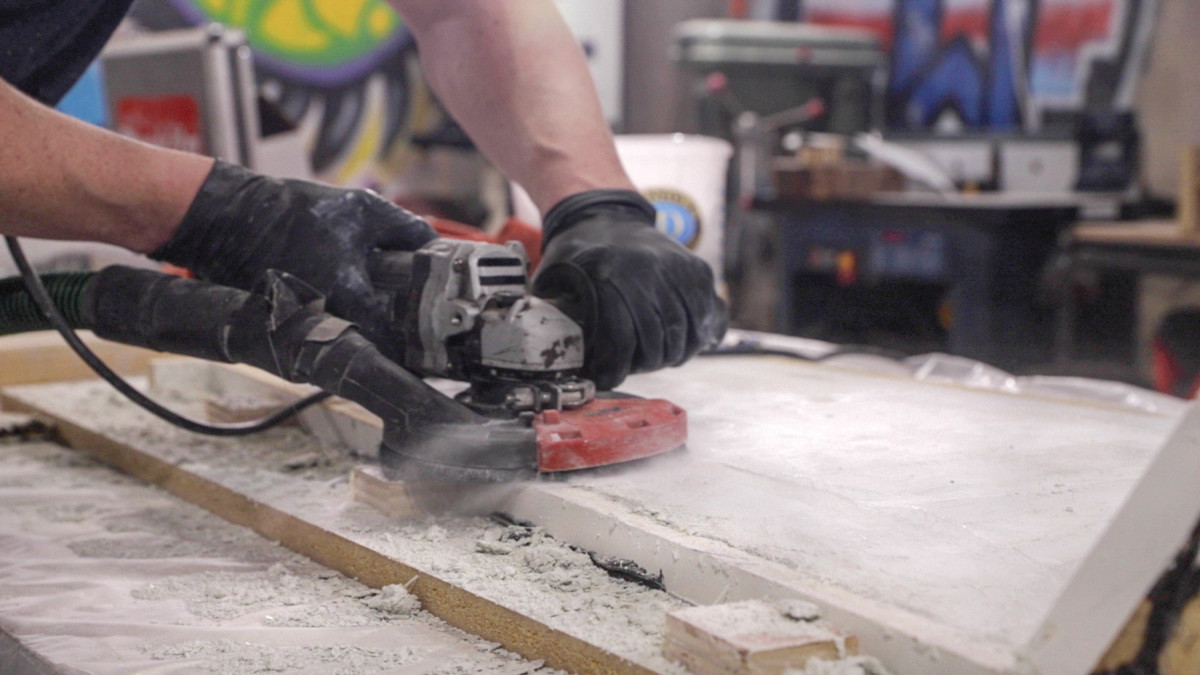
17. Don’t remove the form immediately post-curing. I find it easier to do the rough grinding while the top is still supported by the form.
Taking a concrete project out of the form is like Christmas morning for makers—waiting to see what your project will look like can be difficult! In many cases, GFRC can be removed from the form after 24 hours. However, I waited 48 hours because of the lower temperature in my shop.
18. If there are air pockets or gaps in the concrete, you can apply a slurry mixture of the concrete to fill things in.
Before demolding, I took the opportunity to grind down the underside of the table while it was in the form. Grinding the underside while still in the form allows you to use the sides of the form as a guide to grind to a consistent thickness.
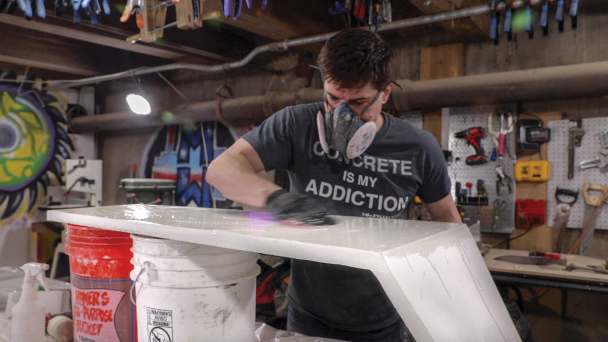
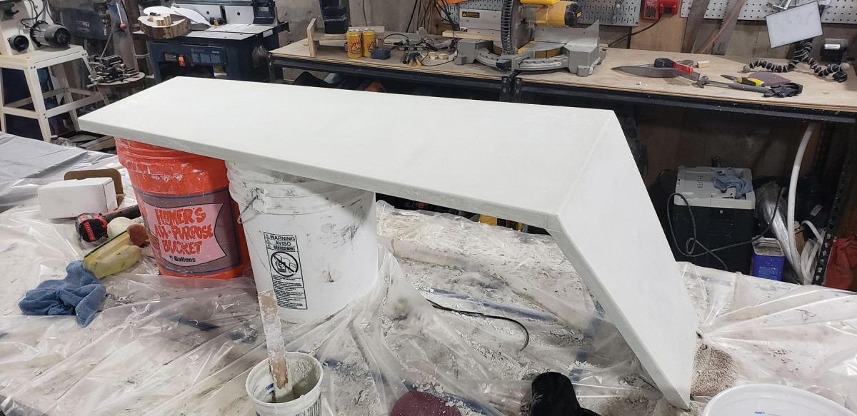
19. Wet sanding the top gives a silky-smooth surface.
There’s really just one rule to demolding a concrete piece: don’t touch the concrete with any tool. I typically use a cheap “sacrificial” chisel, a mallet and my hands, to pry the sides of the form away.
After demolding, I wet-sanded the tabletop by hand with #400-grit sandpaper. A quick, high-grit wet sand is an incredibly easy way to finish GFRC. You simply wet sand until you feel the micro-texture of the melamine disappear under your hand (usually only takes a few seconds in one location). After sanding, I apply a couple coats of concrete sealer with a clean microfiber cloth.
One note before we move on to the woodworking—depending on whether there are any flaws you want to fix, you may want to do a slurry coat (or two) to fill in voids and get a perfectly smooth surface. A slurry coat is just the same GFRC mix as used for the face coat, wiped in by hand to fill any voids or pinholes in the surface. In my case, I applied one slurry coat to patch up some places on the vertical surfaces where the slumping resulted in rough patches.
Concrete & Walnut Table Materials List
Wood:
4 bdft walnut
MOLD:
4’x8′ sheet of melamine particle board
Screws
Concrete:
5 lbs. alkali resistant (AR) glass fibers
AR glass mesh sheet
1 1/2” Tapcon concrete screws
Specialty Tools:
Buckets for mixing and measuring
Concrete paddle mixer
Fondant ball tool (cake decorating tool)
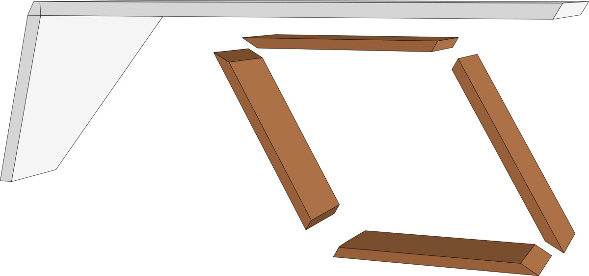
Exploded View
Making the Walnut Base
20-22. I cut the complimentary angles on the table saw. First, with the leg supported on a sled that lips over my fence. Then, the complimentary angle is cut with the workpiece on the table.
To support the other end of the table, I decided on a rhombus-shaped leg made from a single walnut board. I used a single board for a continuous grain pattern. (A rhombus is a parallelogram with opposite, equal acute angles, opposite, equal obtuse angles, and four equal sides. Yes, I had to look it up too.)
 The rhombus slants at 30° in the opposite direction of the 15° leg, meaning the inner acute angles are 60°, while the inner obtuse angles are 120°.
 From a design perspective, I chose a 30° angle because the sharper slant gives the table a more aggressive and dramatic look, while still being proportional to (double) the angle of the 15° waterfall leg.
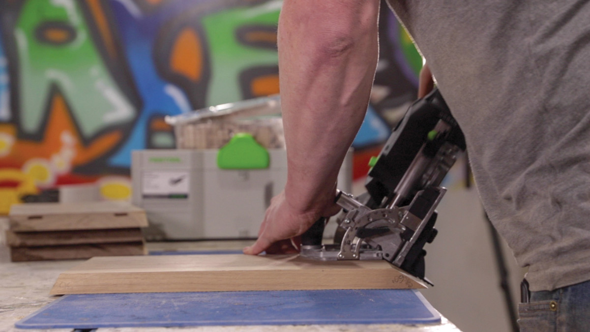
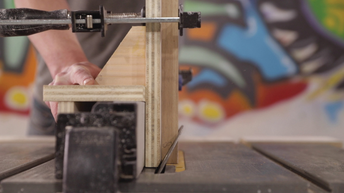
23. I used domino joinery to help align the miters during glue-up and reinforce the corners.
After milling the walnut lumber, I moved on to cutting the miters. The rhombus shape meant that the four sides would be cut identically, with each side having a 30° miter on one end and a 60° miter on the other end. To make the 60° cuts, I used a vertical tenoning jig with the blade set to 30°.
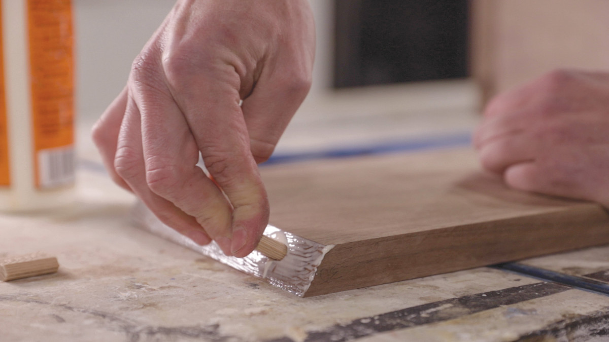
24. The dominos I had on hand were a little long, so I trimmed them with a hand saw.
I then left the blade in the exact same position, and used my miter gauge to make the 30° cuts. (Pro Tip: Any time you’re cutting four pieces for a quadrilateral, make the cuts on one end of all four piece, then cut the other side of all four pieces on the other side of the blade, without moving the blade. This way, any error in the cut angle on one end will be offset by an equal and opposite error on the other end of each board, and you’ll get perfect miters off the blade.)
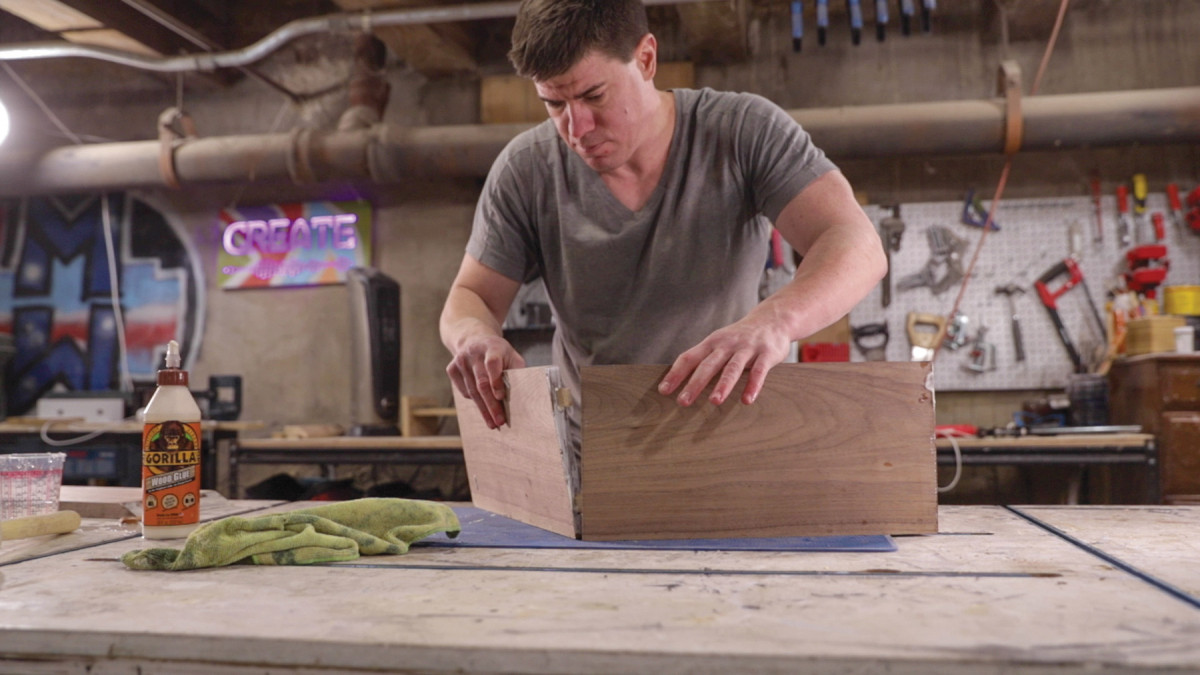
25. Glue-up and assembly of the mitered base is a little tricky. A glue with extended open time helps.
For the joinery, I used Festool’s domino joinery. The only tricky part for this project was the domino size. All I had on hand were 8mm x 40mm dominos (which I definitely wanted for this project), and 40mm was too deep for the sharp angle on the 60° miters. This was easily remedied by using a hand saw to cut the dominos down to 30mm and adjusting my plunge depth.
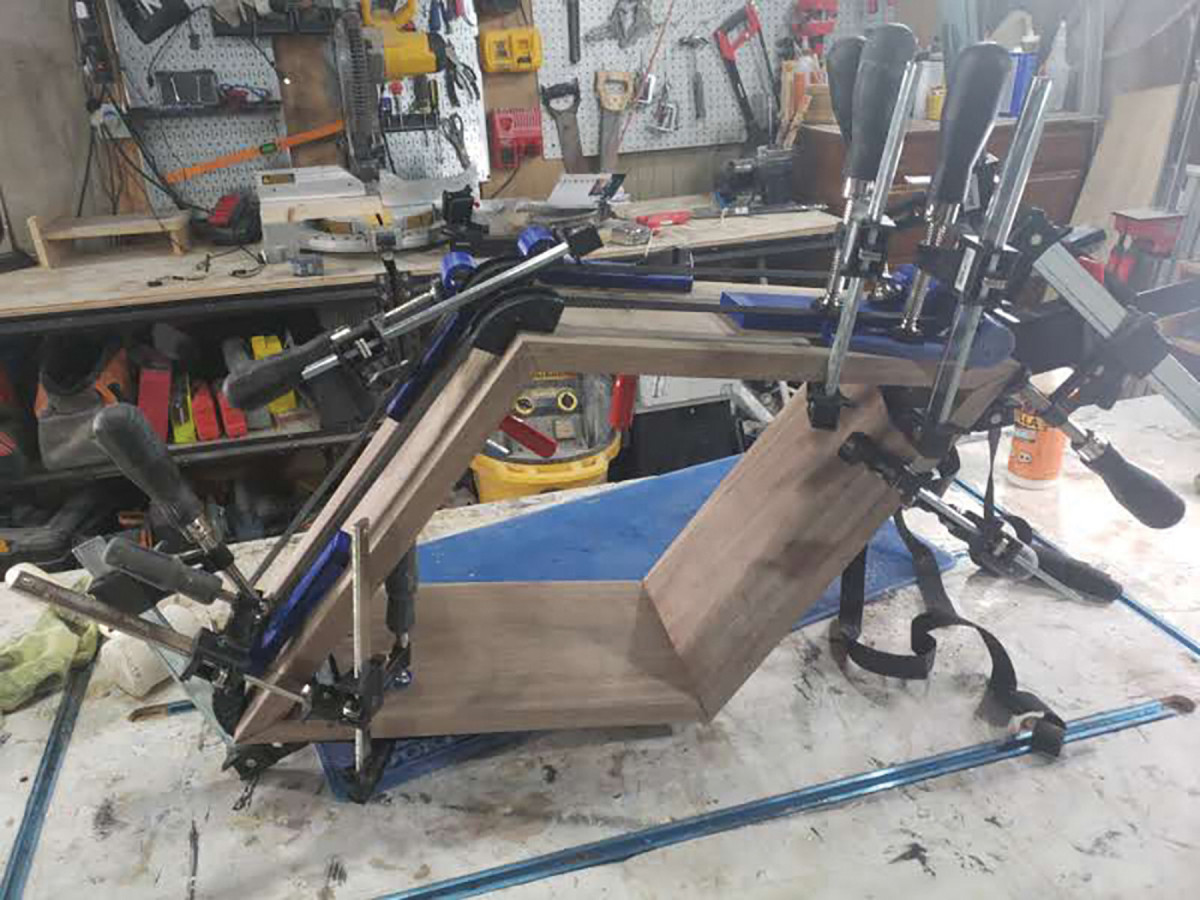
26. Keeping four mitered corners aligned and tight took some tricky clamping. Rehearse this step before there’s glue on the joints.
For the glue up, I first used ratcheting band clamps to quickly get some pressure on the joints, and then used any-angle clamping blocks with F-clamps to apply proper pressure to the miter joints. I 3D-printed the any-angle clamping blocks a few months ago, and was impressed how well they worked, especially because complimentary-angled clamping blocks would get complicated with these angles.
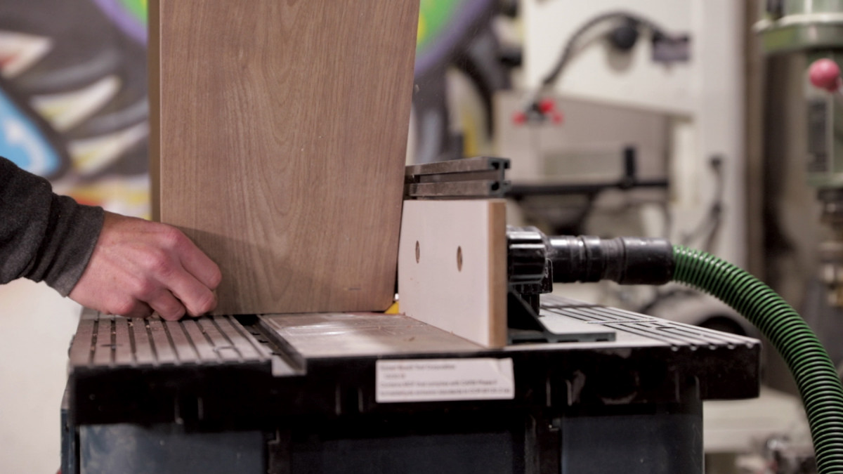
27. I beveled the edges of the base to create a small reveal where the base meets the top and the floor.
Before applying finish, I gave the legs a 45° chamfer. I set up my router table and carefully routed the chamfer on the outside edges. The chamfer provides some separation between the ground and the table leg. I then used a microfiber cloth to wipe on two coats of Maker Brand Simple Finish.
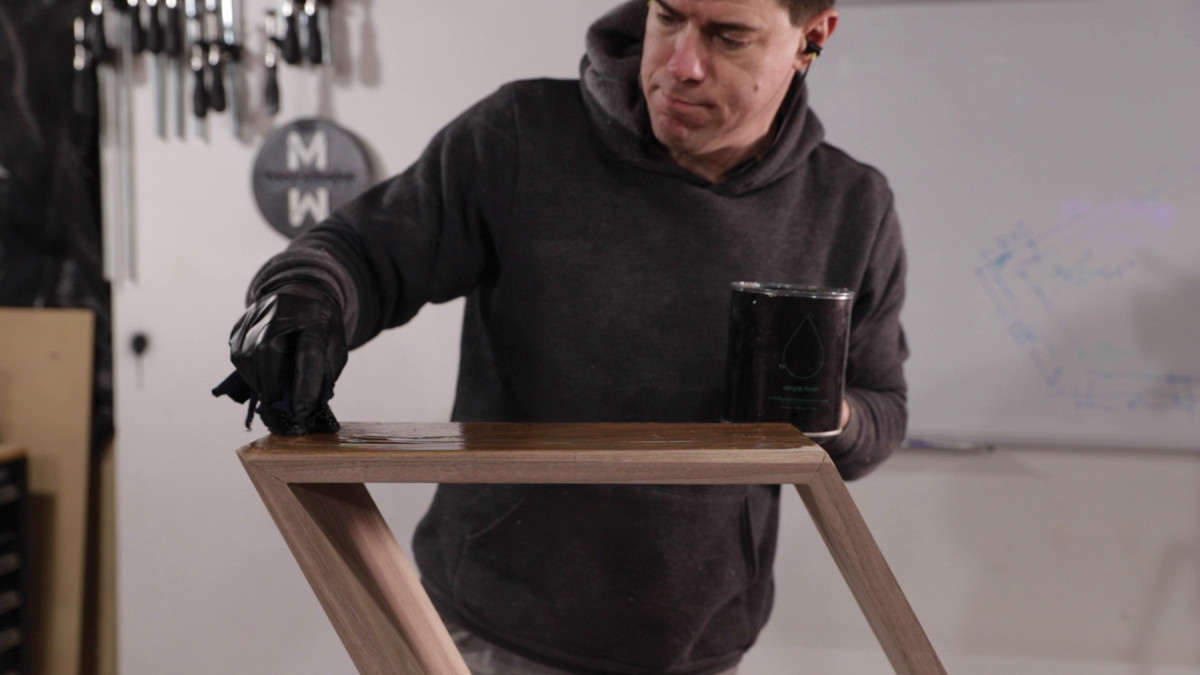
28. A simple oil and wax finish gives the walnut some depth.
I let the finish dry overnight, and then used construction adhesive and four 1 1/2” Tapcon concrete screws to attach the wood base to the tabletop. With that, the table was done.
Michael Clifford is a maker based in Chicago. You can see more of his work, including a video of building this table, at modustrialmaker.com.
Here are some supplies and tools we find essential in our everyday work around the shop. We may receive a commission from sales referred by our links; however, we have carefully selected these products for their usefulness and quality.