We may receive a commission when you use our affiliate links. However, this does not impact our recommendations.
 As the old saying goes, sometimes you have to learn to walk before you can run. That’s certainly been true in my career as a cabinetmaker: I’ve tried to learn the basics on small projects, where I could afford to make mistakes, before tackling the really ambitious work that I’ve had my heart set on for years.
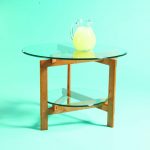
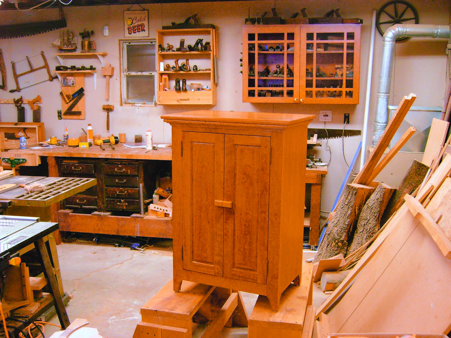
This utility cabinet is one of those small projects. I built one like it years ago, when my wife Bo needed more storage space and I needed an opportunity to hone my skills in building face frames and making and fitting doors. Of course, we still need more storage space now, so I thought I’d build another one and share the whole process with you.
Build the Case
Although you could make this whole cabinet out of solid wood, I built the case from veneer-core plywood, to save time and money. You’ll need one sheet of 3/4″ material plus a small piece of 1/4″ material for the back. Start by cutting the sides (A1) and subtop and bottom (A2) to their finished sizes. Be sure that their edges are straight and that the pieces are square.
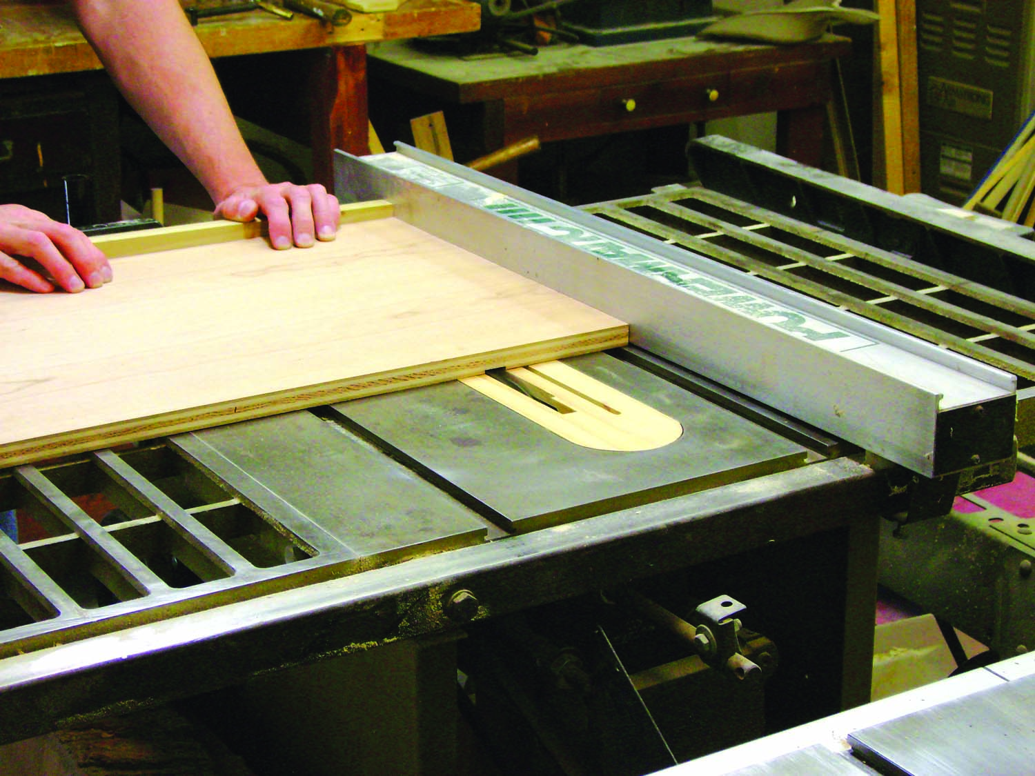
Photo 1. Dado and rabbet the sides of the cabinet to receive the bottom and the subtop. Although you’ll be fastening the cabinet together with pocket screws, dadoes make the parts much easier to align.
Cut shallow dadoes across the sides to receive the bottom (Photo 1 and Fig. 07). I like to use pocket screws to assemble plywood cabinets, so a dado isn’t strictly necessary here. But I like the way that the dado registers and aligns the bottom during glue-up, so I think it’s worth the extra time. If your plywood is slightly less than 3/4″ thick, set up a dado set that’s 11/16″ wide and add shims until it cuts a dado that fits your plywood.
Next, cut rabbets on the ends of the sides to receive the subtop. Leave the dado set at the same height and clamp a sacrificial board to your fence—the blade will go right up next to it.
Reset the fence and adjust the dado set’s height to cut rabbets for the back (A3). While the sides are still loose pieces, drill holes for the shelf pins (Fig. 07).
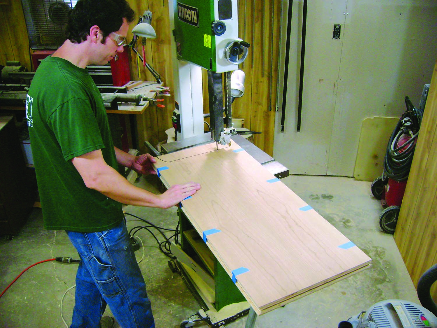
Photo 2. Cut out the legs of the side pieces. Tape them together so you can cut both pieces at the same time.
Tape the side pieces together, inside to inside. Lay out the feet on the top piece (Fig. 07). (Note that the back feet are wider than the front feet; the front feet will become wider when you add the face frame.) Cut out the feet on the bandsaw (Photo 2). Smooth the rough edges of the cut with a half-round file and coarse sandpaper.
Drill pocket holes in the subtop and bottom pieces (Fig. 02). The exact spacing of the holes isn’t important. My pocket hole jig was set up for drilling pairs of holes in face frames, so I drilled these holes in pairs, too. Temporarily assemble the cabinet. (Note that you must use 1″ long pocket screws, which are shorter than normal. That’s because the dadoes and rabbets you cut into the sides effectively reduced the sides’ thickness to 5/8″.)
Place the case face down. Cut the back to fit and put it in place. Make sure the case is square, then predrill holes for screws through the back.
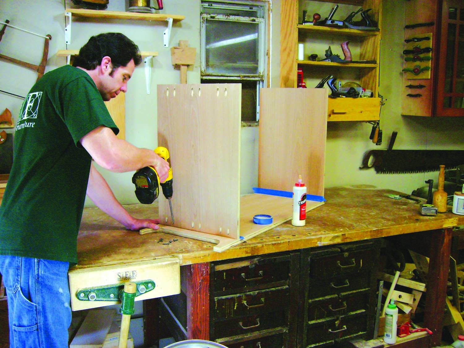
Photo 3. Glue the bottom and subtop to the sides. Fasten them with pocket screws, so you don’t have to use any clamps.
Glue and screw the subtop and bottom pieces to the sides (Photo 3). Install the back right away, with screws, before the glue sets. This will ensure that the cabinet is square.
Make the Face Frame
During my years as a professional cabinetmaker, I’ve seen half a dozen different ways to build and attach a face frame. Some guys build it oversize, so it hangs over the cabinet’s edge all round. They’ll glue it to the cabinet, then trim it flush with a router. I do things differently: I make the face frame the same size as the cabinet, with no overhang.
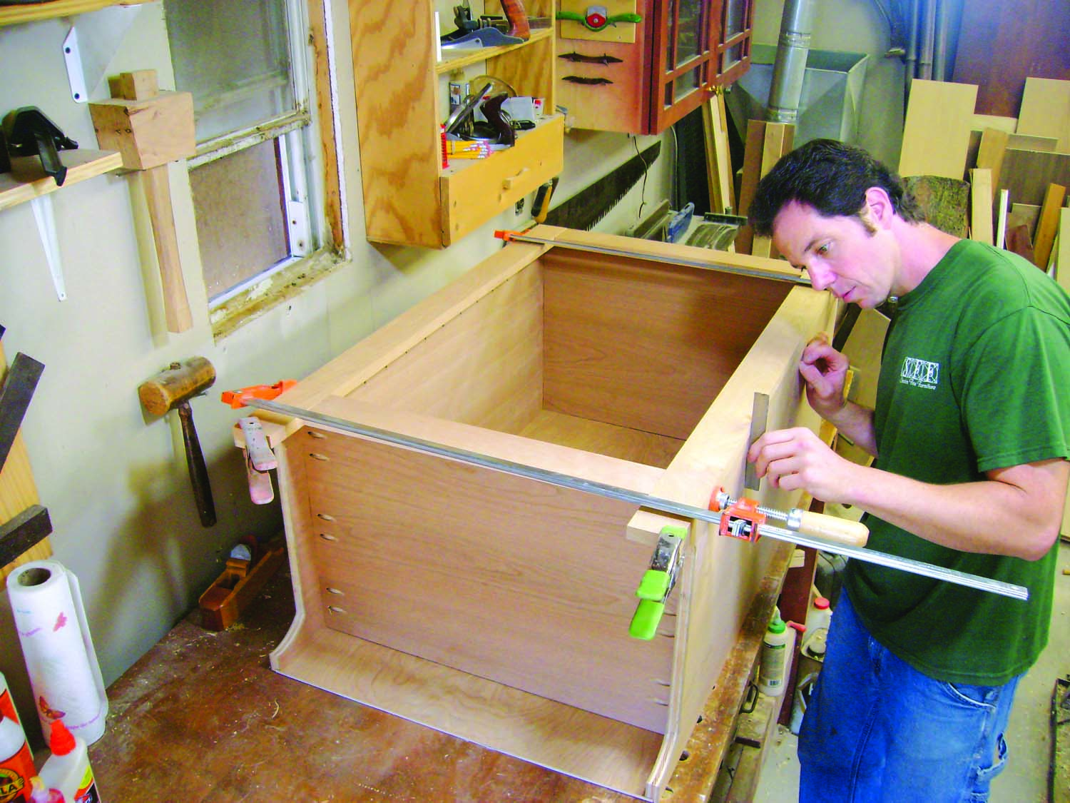
Photo 4. Make a face frame that exactly fits the cabinet. Temporarily clamp up the face frame, place it on the cabinet, and make sure its edges are flush with the cabinet’s sides.
Mill the rails and stiles for the face frame (B1 and B2) to final thickness and width, but leave them about 1″ extra-long. Trim the stiles so they’re the same length as the cabinet’s sides, then trim the rails to their final length. Double-check the lengths of the rails by clamping the face frame together; it should be flush with the cabinet on both sides (Photo 4). Position the face frame so it’s flush with the bottom of the cabinet, then reposition the lower rail, if necessary, so it’s flush with the cabinet’s bottom. Mark the rail’s location on the stiles.
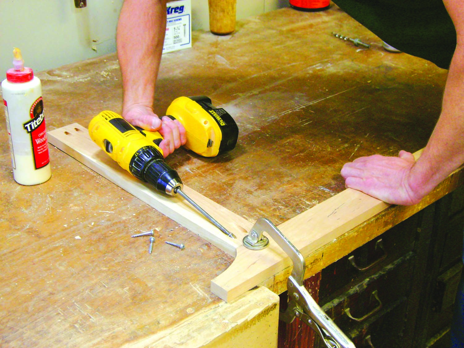
Photo 5. Once you’re sure that the face frame fits, cut the bottom end of each stile to form a leg. Glue and screw the face frame together.
Bandsaw legs on the bottom ends of the stiles. These legs should be the same width as the rear legs on the cabinet’s sides. Drill pocket holes in the rails, then glue and screw the face frame together (Photo 5). Make sure it is square by measuring its diagonals or by using a framing square.
Cut a number of biscuits slots on the cabinet and corresponding slots on the face frame.
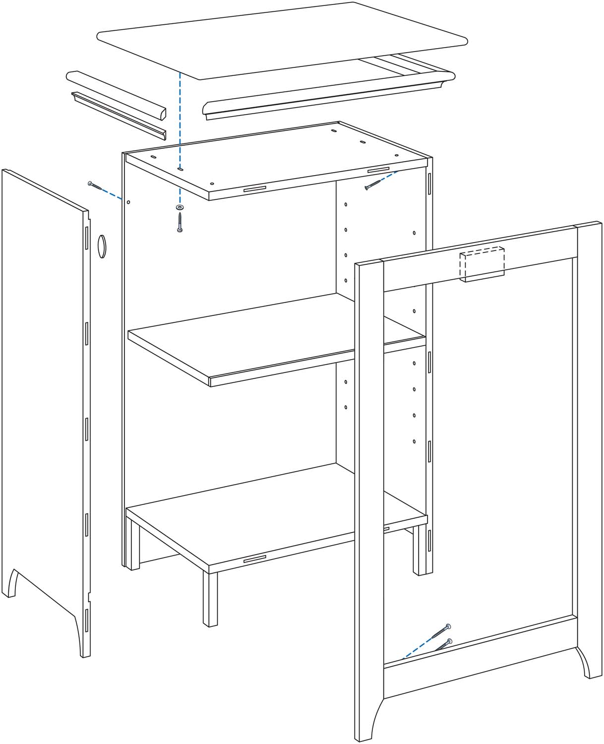
Fig. 01. Exploded View
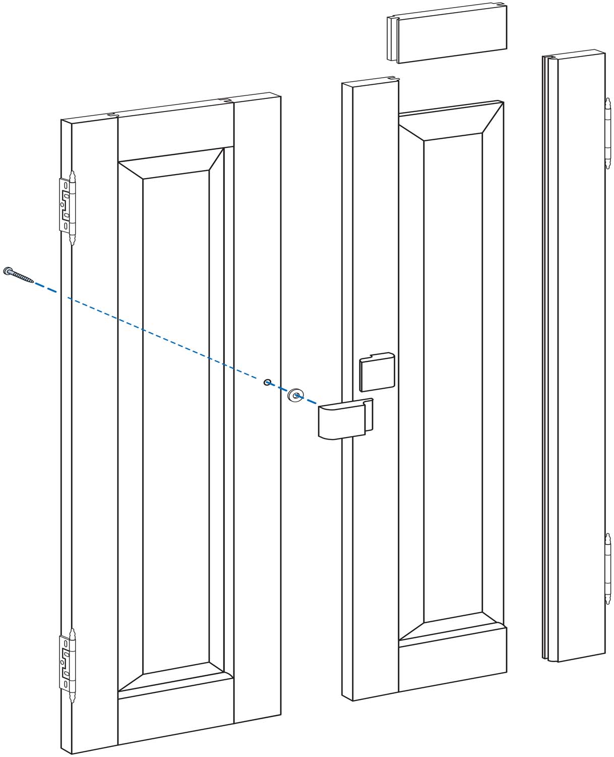
Fig. 02. Door Construction

Fig. 02. Case Pocket Holes
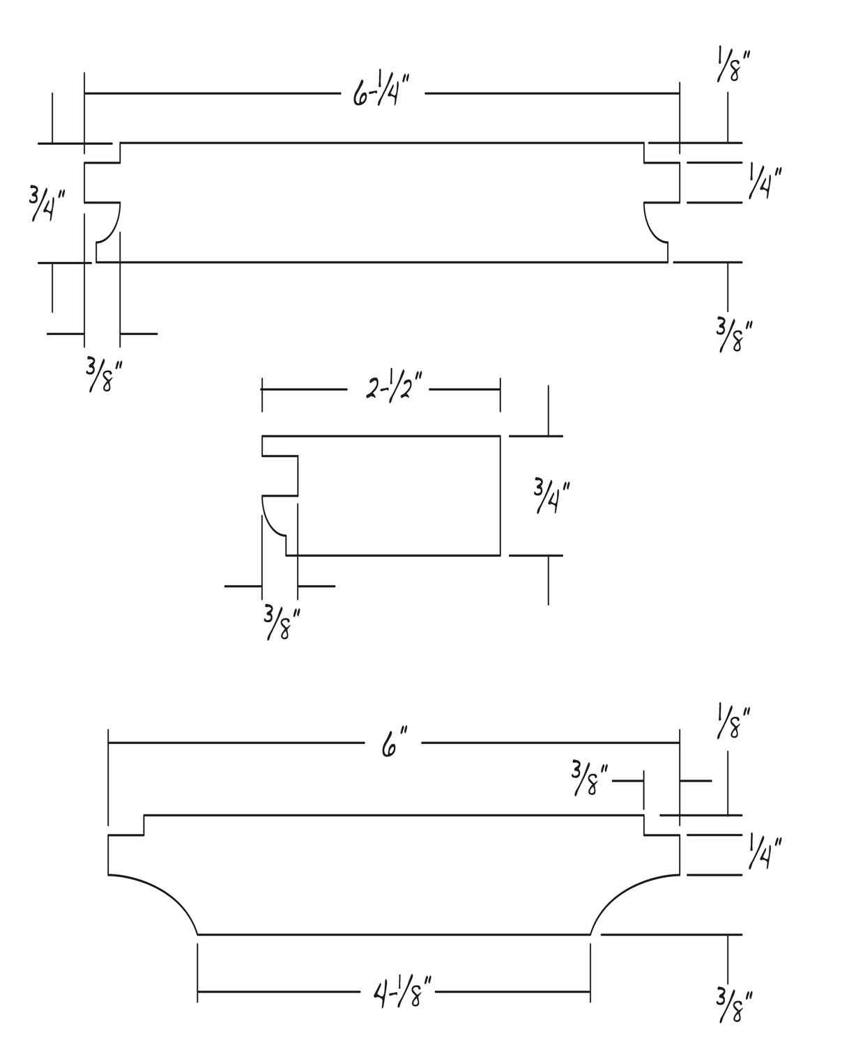
Fig. 04. Door Details
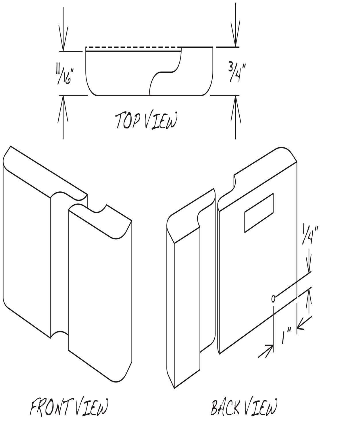
Fig. 05. Door Handle

Fig. 06. Molding Profiles
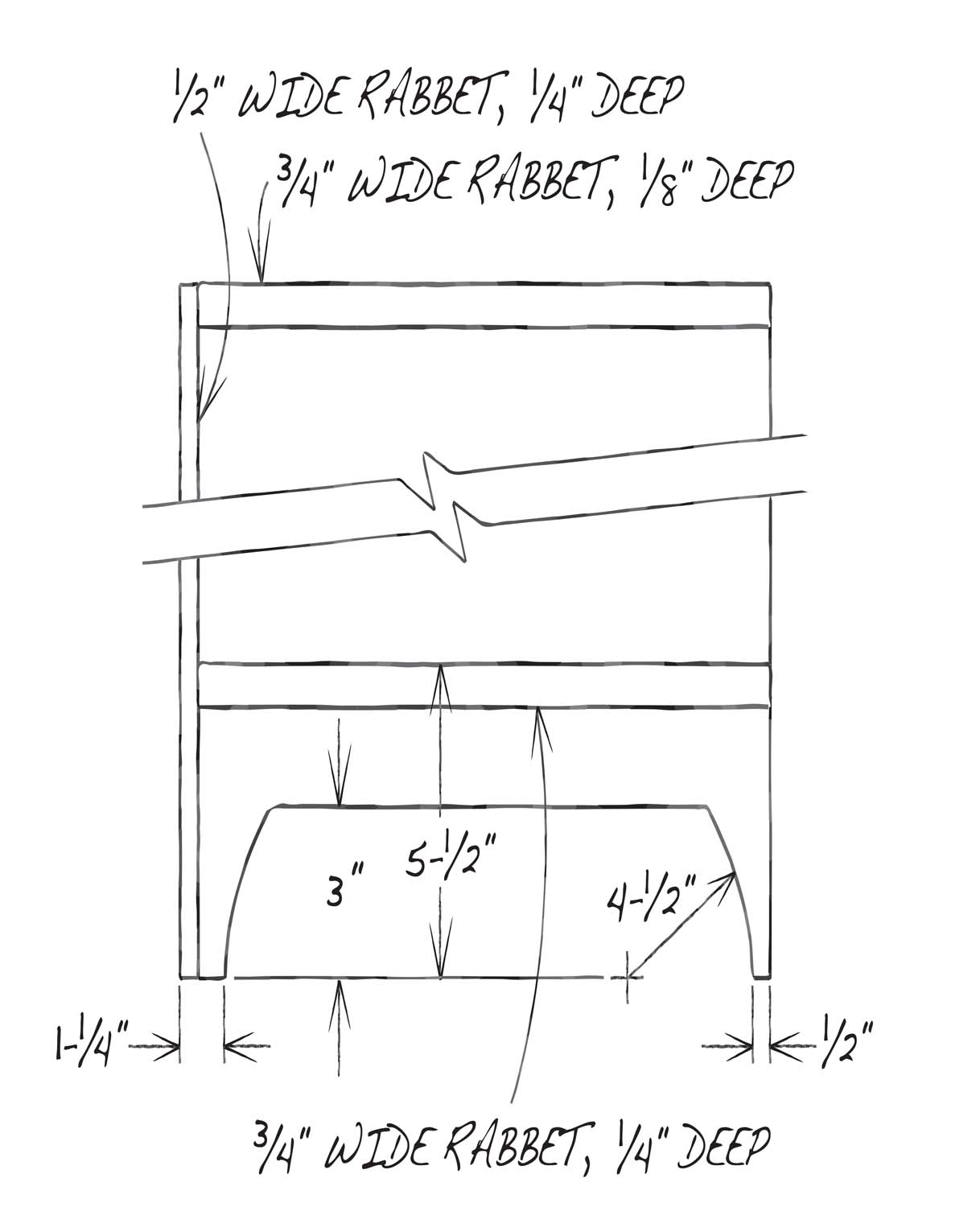
Fig. 07. Side Details
Cut List
|
Chad’s Cabinet |
|||||
|
Overall Dimensions: 39-3/4″ H X 28-1/2″ W x 18-3/4″ D |
|||||
|
Section |
Part |
Name |
Qty. |
Material |
Th x W x L |
|
Case |
A1 |
Side |
2 |
Ply |
3/4″ x 16-1/4″ x 39″ |
|
A2 |
Subtop and bottom |
2 |
Ply |
3/4″ x 16″ x 23-3/4″ |
|
|
A3 |
Back |
1 |
Ply |
1/4″ x 24-1/2″ x 39″ |
|
|
A4 |
Shelf |
1 |
Ply |
3/4″ x 15-3/4″ x 23-3/8″ |
|
|
A5 |
Shelf edging |
1 |
Solid |
1/8″ x 3/4″ x 23-3/8″ |
|
|
A6 |
Corner block, front |
2 |
Solid |
3/4″ x 1-1/4″ x 4-3/4″ |
|
|
A7 |
Corner block, back |
2 |
Solid |
3/4″ x 2-1/4″ x 4-3/4″ |
|
|
Face frame |
B1 |
Rail |
2 |
Solid |
3/4″ x 2-1/2″ x 20″ |
|
B2 |
Stile |
2 |
Solid |
3/4″ x 2-1/2″ x 39″ |
|
|
B3 |
Door stop |
1 |
Solid |
3/4″ x 2-1/4″ x 4″ |
|
|
Door |
C1 |
Rail |
4 |
Solid |
3/4″ x 2-1/2″ x 6-1/4″ (a) |
|
C2 |
Stile |
4 |
Solid |
3/4″ x 2-1/2″ x 30-7/8″(b) |
|
|
C3 |
Panel |
2 |
Solid |
3/4″ x 6″ x 26-5/8″ |
|
|
C4 |
Handle, fixed side |
1 |
Solid |
3/4″ x 2-1/4″ x 2″ (c) |
|
|
C5 |
Handle, pivot side |
1 |
Solid |
11/16″ x 2-1/4″ x 2-7/8″ (c) |
|
|
Top |
D1 |
Top |
1 |
Solid |
3/4″ x 18-3/4″ x 28-1/2″ |
|
D2 |
Bullnose molding, front |
1 |
Solid |
3/4″ x 1-1/4″ x 27-1/2″ |
|
|
D3 |
Bullnose molding, side |
2 |
Solid |
3/4″ x 1-1/4″ x 18-1/4″ |
|
|
D4 |
Cove molding, front |
1 |
Solid |
5/8″ x 3/4″ x 26-1/2″ |
|
|
D5 |
Cove molding, side |
2 |
Solid |
5/8″ x 3/4″ x 17-1/2″ |
|
|
Notes (a) This length is oversize; it should be 1/16″ more than the height of the opening in the face frame. (b) Adjust the length, if necessary, so the doors fit tight across the face frame’s opening. (c) Cut from one piece 3/4″ x 2-1/4″ x 4″. |
|||||
Fit the Doors
You’ve got a lot of options for making the doors, so I won’t go into much detail. I use a standard set of cope and stick router bits to join the stiles and rails (C1 and C2) and a large cove bit to shape the panels (C3). (See Figs. 03 and 04). After cutting the coves, I rabbet the back sides of the panels so the panels will fit into the grooves in the stiles and rails.
I usually make my doors oversize to begin with, then methodically trim them until there’s about 1/32″ clearance all around. Before fitting, they are 1/16″ taller than the opening in the face frame. Their width is generous, too: Placed side by side, the doors should fit tight across the opening. (However, if you’re off in width by up to 1/16″, one way or the other, it really doesn’t matter.) Note that the dimensions given in the cutting list are for these oversize dimensions— they are not the final sizes of the door’s rails and stiles.
Fitting the doors is much easier to do with the face frame lying flat on my bench rather than attached to the cabinet; this way, I don’t have to rig up something to support the doors—they lay right on the bench, too.
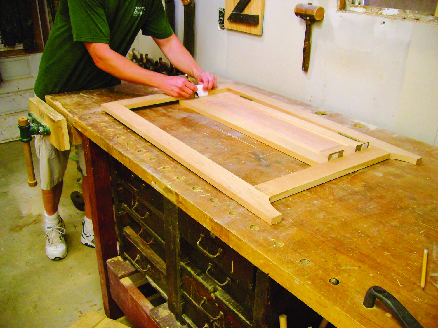
Photo 6. Make the doors and fit them inside the face frame. Use shims to establish the correct clearances. This process is much easier when you can lay the face frame flat on a bench.
A set of plastic laminate shims—which are about 1/32″ thick—are invaluable for trimming the doors. After gluing each door together, fine-tune its length. Lay one door on the bench and place the face frame on top of it. Place two shims between the bottom of the door and the face frame’s lower rail. Because the door is oversize, the top rail of the face frame should now sit on top of the door. Using another shim as a spacer, scribe a fine pencil line along the top of the door (Photo 6). Cut as close to this line as you can on the tablesaw, using a crosscut sled. If the line was slightly tapered, use a plane to finish the job. The door should now have a perfect 1/32″ clearance top and bottom.
Theoretically, you could have just cut the doors to the right length on the tablesaw, but my experience has taught me that this can be risky. If the face frame is just a little bit out of square, scribing is the only way to correct the error.
Scribing isn’t necessary for trimming the door’s width, however. For this operation, use a jointer to remove an equal amount of material on both of the hinge-side stiles until you can fit shims where the hinges will go (the hinges require about 1/32″ clearance, too.) At this point, the doors and shims should fit tight across the face frame, with little or no gap in the center.
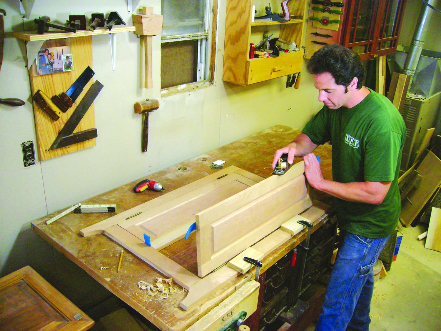
Photo 7. Attach hinges to the doors and plane bevels on both inner stiles. These bevels allow the doors to close with a minimum amount of gap between them.
Next, mount the hinges on the doors and hang the doors inside the face frame (Fig 03). Trim the center stiles by hand, using a block plane (Photo 7). Both of these stiles must be beveled about 2° so the doors will close properly. You don’t need a protractor, however. Just scribe a line 1/32″ down on the inside edge of each stile and bevel the stile until you get to the line. Then plane the entire bevel until there’s an even, 1/32″ gap between the doors when they’re closed.
Photo 8. Glue and clamp the face frame to the cabinet. Align the pieces with biscuits.
Remove the doors from the face frame and glue the face frame to the cabinet (Photo 8).
Make the Top and Moldings
Glue up the top (D1), sand it even and rout a bullnose rounding on its front and side edges (Fig. 06). (I do this on the router table, using a roundover bit.) Using the same setup, make the bullnose moldings that go under the top (D2 and D3).
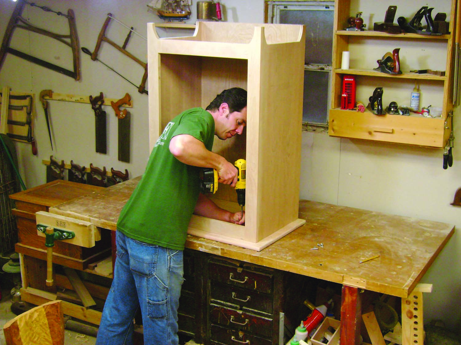
Photo 9. Make a top from solid wood and fasten it to the cabinet. Drill elongated holes in the cabinet’s plywood subtop so the solid-wood top can expand and contract without cracking.
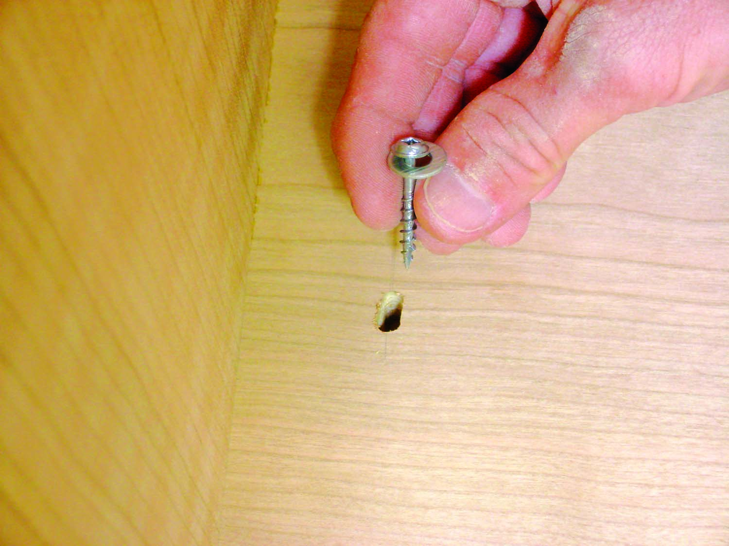
Photo 9B. Plywood subtop.
Drill holes in the subtop for fastening the top (Fig. A). Note that two of the holes on each side must be oval, so the top is free to expand and contract. Fasten the top to the cabinet with screws and washers (Photo 9).
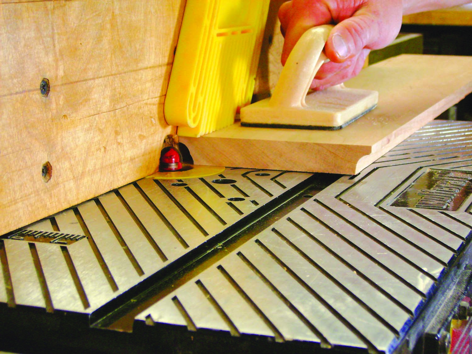
Photo 10. Shape two coves on a board, then rip the board to make two moldings. Although this router bit is round, adjusting its height and depth a few times yields a nice, elliptical shape.
Make the cove moldings that also go under the top (D4 and D5, Fig. 06). Rout the edges of a board that’s about 4-5″ wide (Photo 10), then rip the moldings from the board. You can create this molding’s elliptical shape using a standard cove bit, which has a round profile, by making a series of overlapping passes. Just adjust the height and depth of the cut a few times, then remove any small waves between the cuts by sanding.
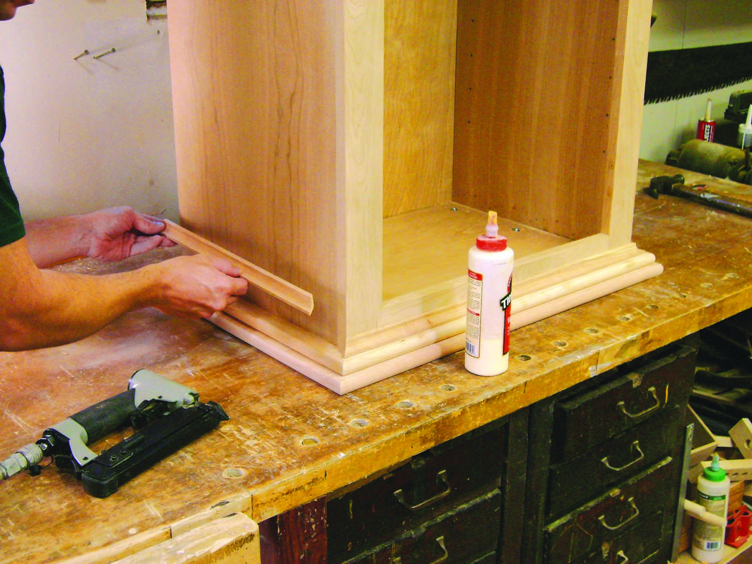
Photo 11. Glue the moldings to the case, but not to the solid-wood top. These pieces run across the width of the top; gluing them to the top would restrain the top from moving and may cause it to crack.
Trim the front bullnose molding to length first, and glue it to the case. Cut both side pieces next, and glue them as well. Repeat the procedure for the cove moldings (Photo 11).
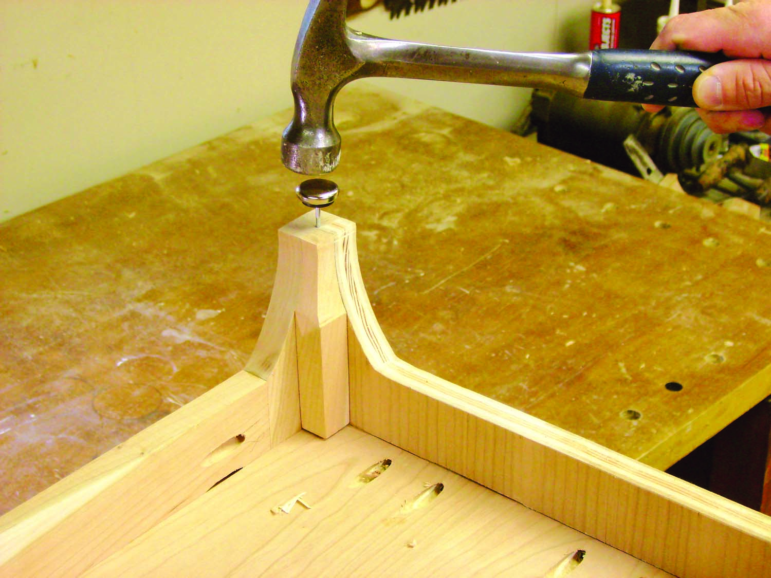
Photo 12. Attach glides to the ends of the legs. Glides prevent the plywood sides from splintering when the cabinet gets pushed across the floor, which is bound to happen!
While the cabinet is upside down, make and install corner blocks (A6 and A7) to reinforce the legs. These blocks also provide more material for supporting furniture glides (Photo 12). Predrill holes for the glides before tapping them in place.
Turn the cabinet back on its feet and glue a block (B3) inside the face frame to stop the doors. Hang the doors on the cabinet and install the handles.
Remove the handles, doors, top and back for finishing. Apply finish to both sides of the top to prevent it from warping.
Making Flush-Fit Handles
 I had a funny urge when designing this cabinet. Although its doors have a traditional look, why not give the handles an ultra-modern touch? When closed, they would be flush with each other, forming a single design element. When open, they’d become two pulls with different, graceful shapes.
If there’s one thing a woodworker truly enjoys, it’s that an abstract idea can soon become reality. I made a few prototypes to perfect the design, but, in the end, these handles proved to be quite easy to make. They would work well on many types of doors.
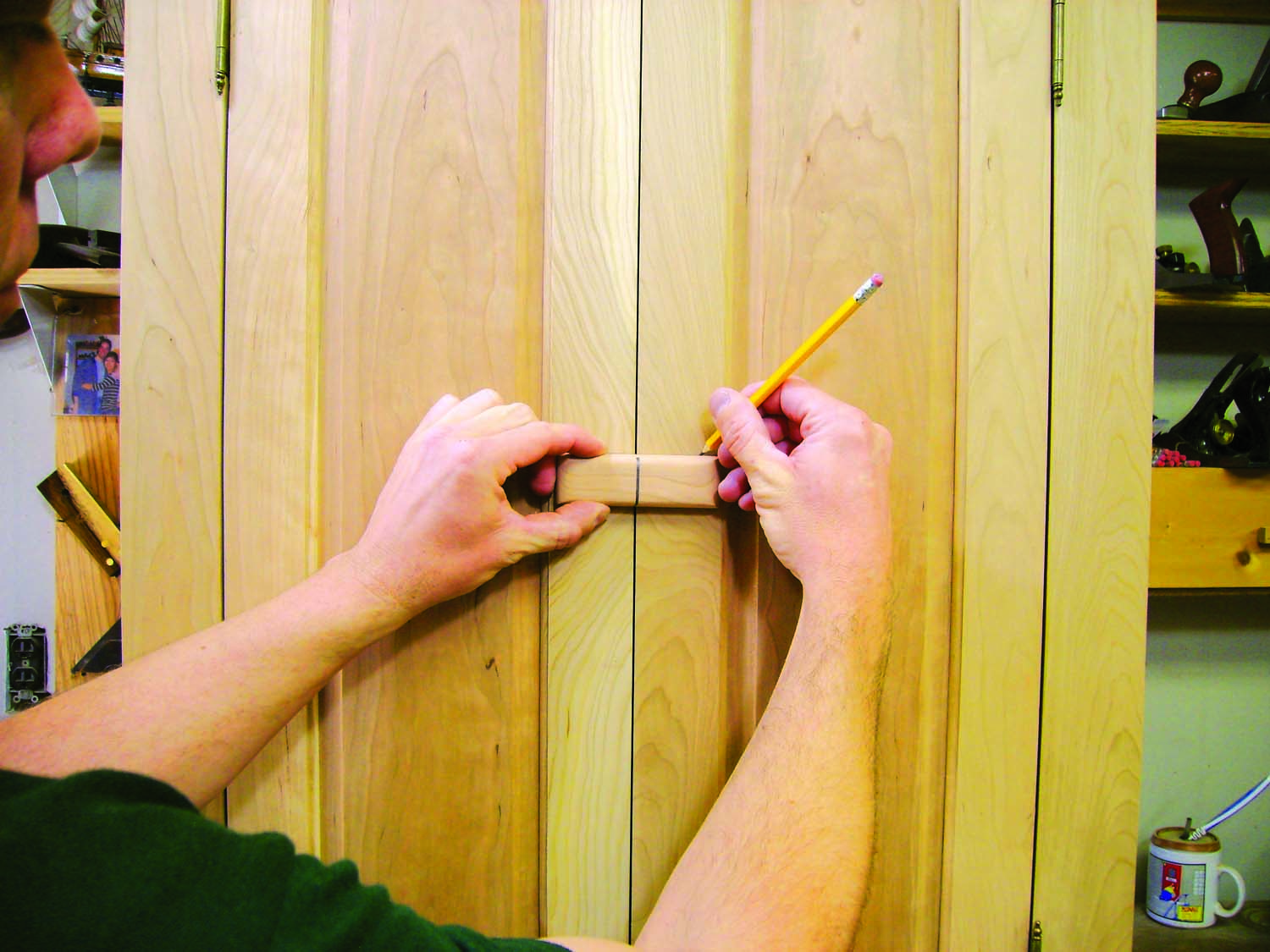
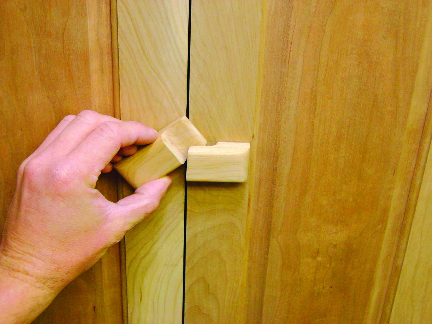
Photo A. Position the handle on the cabinet and trace around it. At this point, the handle is a single block.
Start out with one block of wood (see Cutting List). Mark a centerline around the block, position it on the doors and trace around it (Photo A). Round over the block’s edges with a belt sander and mark “Left” and “Right” on the block’s back side.
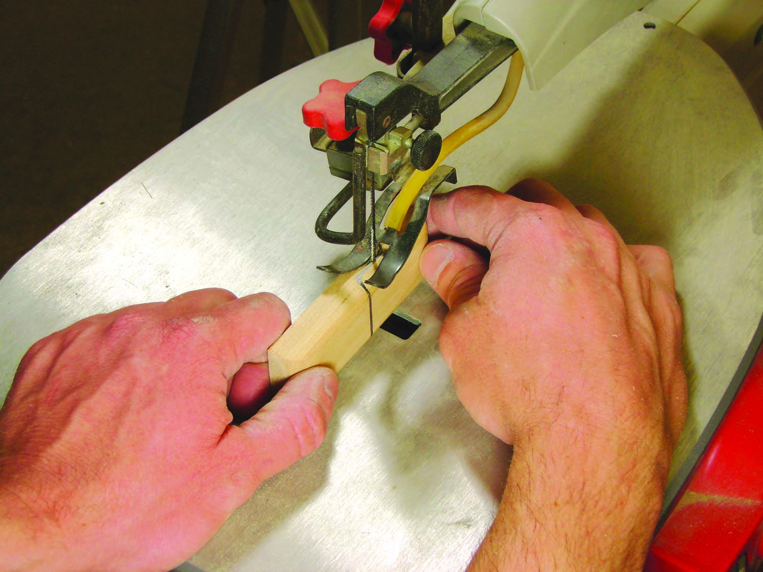
Photo B. Cut the handle into two pieces on the scrollsaw.
Draw an ogee curve on top of the block (Fig. 05). Begin the curve, from front to back, on the block’s centerline. Saw the curve on a scrollsaw (Photo B). (You could also use a bandsaw with a 1/8″ blade.) File and sand the rough surfaces smooth.
Glue the right handle (C4) to the door within the lines you marked—its left end should align with the edge of the door.
Using a belt sander or block plane, reduce the thickness of the left handle (C5) by about 1/16″. (This side must be thinner so it can pivot on a washer.)
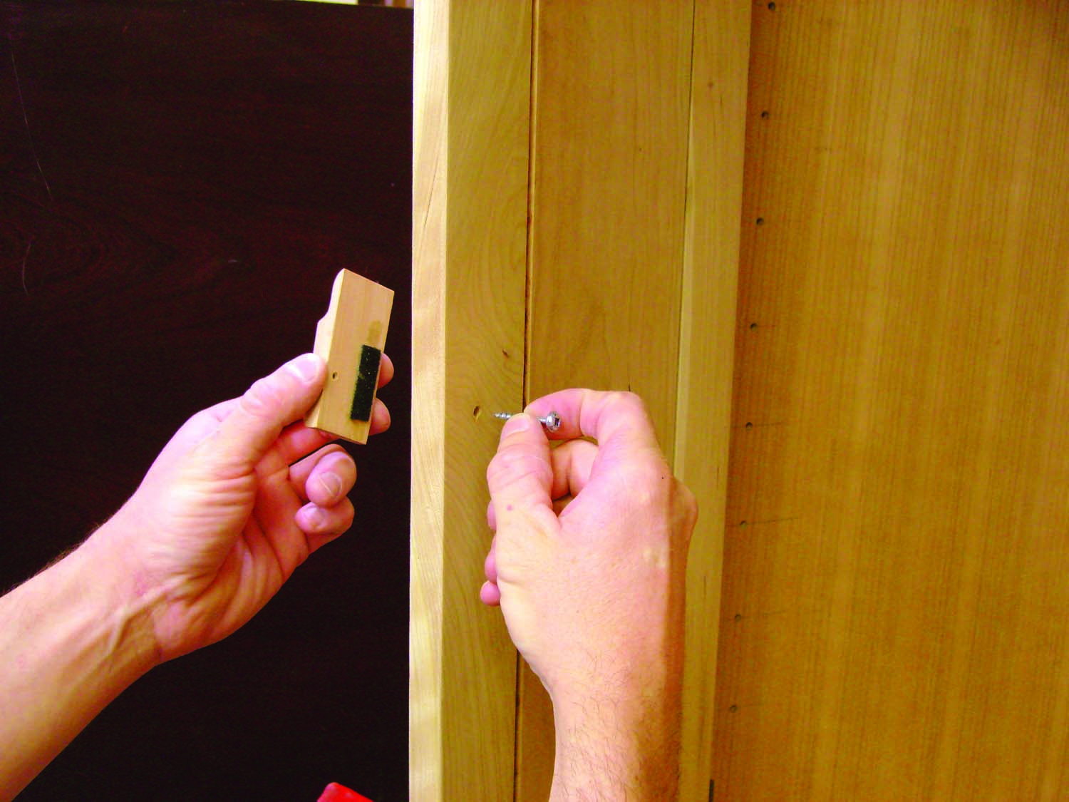
Photo C. The left piece pivots on a screw. The right piece is fixed to the door.
Drill a hole through the door for mounting the handle. (Photo C) This hole should be 1/4″ above the line marked on the door and 1″ from the edge of the door. Place the handle on the door, butted up to the part that’s glued to the door and positioned slightly above the hole. Mark the location of the hole on the handle, then drill the handle to receive the screw.
Glue a piece of felt to the left handle—this will prevent it from scratching the finish. Fasten the handle, placing a washer between the handle and the door. Test the handle’s operation. If it’s too tight, file or sand the ogee.
Here are some supplies and tools we find essential in our everyday work around the shop. We may receive a commission from sales referred by our links; however, we have carefully selected these products for their usefulness and quality.