


We may receive a commission when you use our affiliate links. However, this does not impact our recommendations.
 The bandsaw has always been the prima donna machine in my shop. It requires so much time and attention to make it work right; changing blades, adjusting tension and repositioning guides. It was so time consuming that I would use the wrong size blade or a dull blade instead of going to the trouble of changing it. It was the problem of having to reach over my head to turn a knop that would remove and reapply the tension on the blade that finally started me thinking about a way to eliminate that problem.
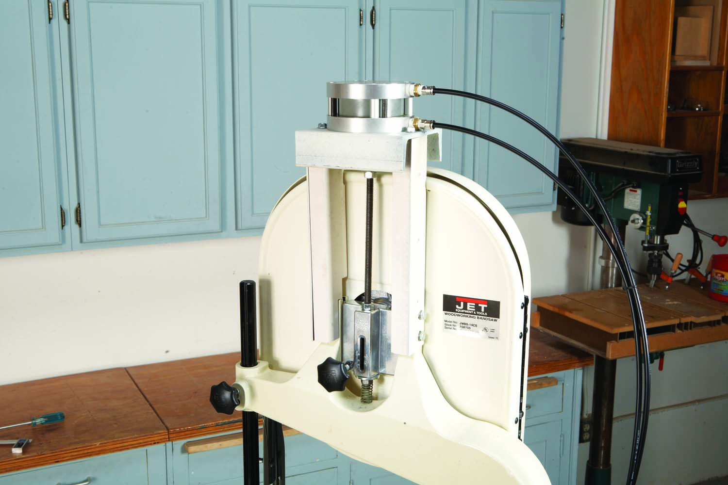
Simple Modification: Replacing your saw’s spring-tension system with an air-powered piston is quite simple. No special skills are required.
By attaching an air cylinder over the top of the bandsaw and connecting the piston rod to the upper wheel bearing housing, where the spring is located, I could apply tension easily by simply turning the knob of an air regulator. By placing a directional air valve between the cylinder and the regulator, I could reverse the air pressure and have the upper wheel pushed down for convenient blade changes.
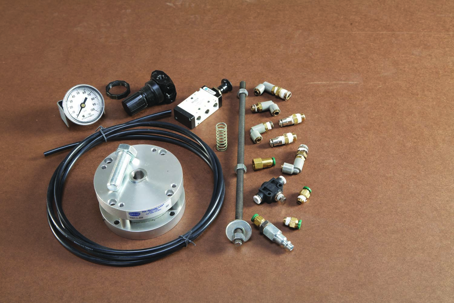
Off-The-Shelf Components: All of the parts for the air system are easy to obtain and assemble. The total cost is about $275.
A secondary, and very handy, advantage is that by having a pressure gauge hooked up to the regulator, I could accurately control the tension on the blade. This will solve the perpetual problem of “does this tension gauge that came with the saw REALLY work?” There is a direct relationship between the air pressure applied to the air cylinder and the amount of tension on the blade, a relationship that can be worked out mathematically. The only other device needed to make the system work is a needle valve which slows the speed of up and down movement of the upper wheel.
Accurate Tension Control: With an air-powered system, you just turn a knob to adjust blade tension. You’ll need a small air compressor, of course, but it won’t run much.
Replace the tensioning system
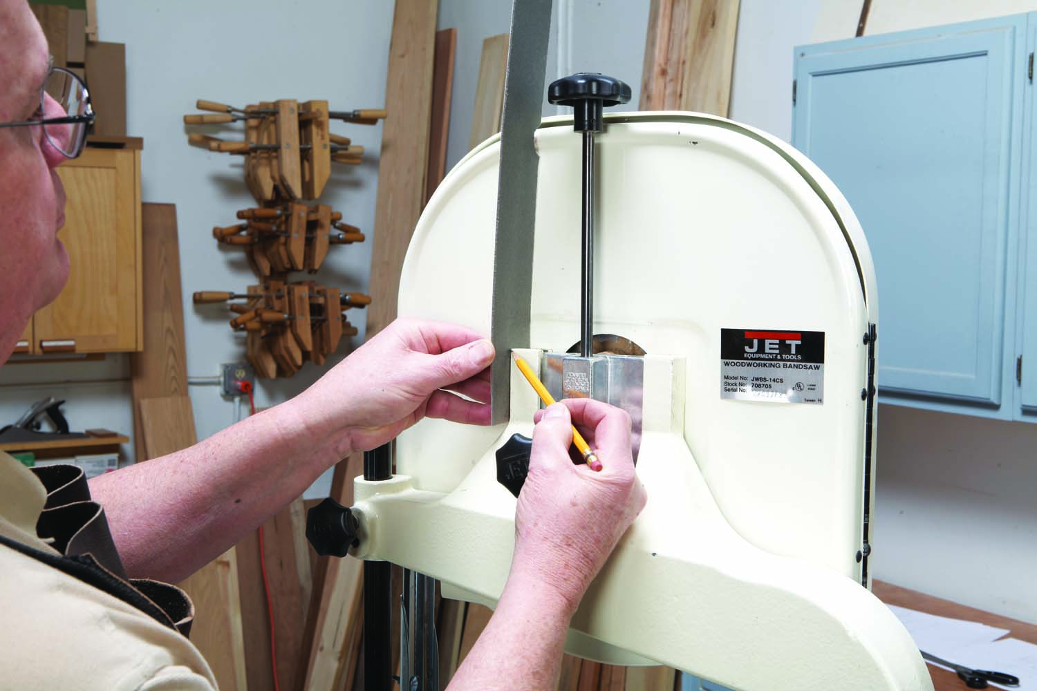
Photo 1. Trace around the contours of your saw to make a pattern.
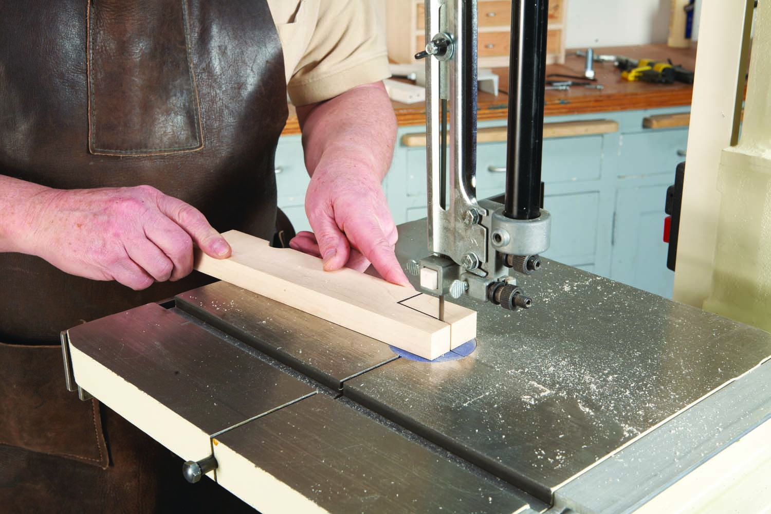
Photo 2. Draw the pattern on two blocks of wood and cut them out. These parts—called riser blocks (A1)—will support the air cylinder.
The first items you’ll make are two brackets for supporting the air cylinder. Each bracket is composed of two parts: a wood riser block (A1) and a steel stiffening plate (B1)—see Fig. A. The riser blocks must be shaped to fit the back of your saw. Make a pattern (Photo 1), transfer the pattern to the riser block blanks, then cut the blanks (Photo 2). Chop a recess in each blank to receive the saw’s sliding bracket (Photo 3; Fig. A)—this part moves up and down as the saw is tensioned.
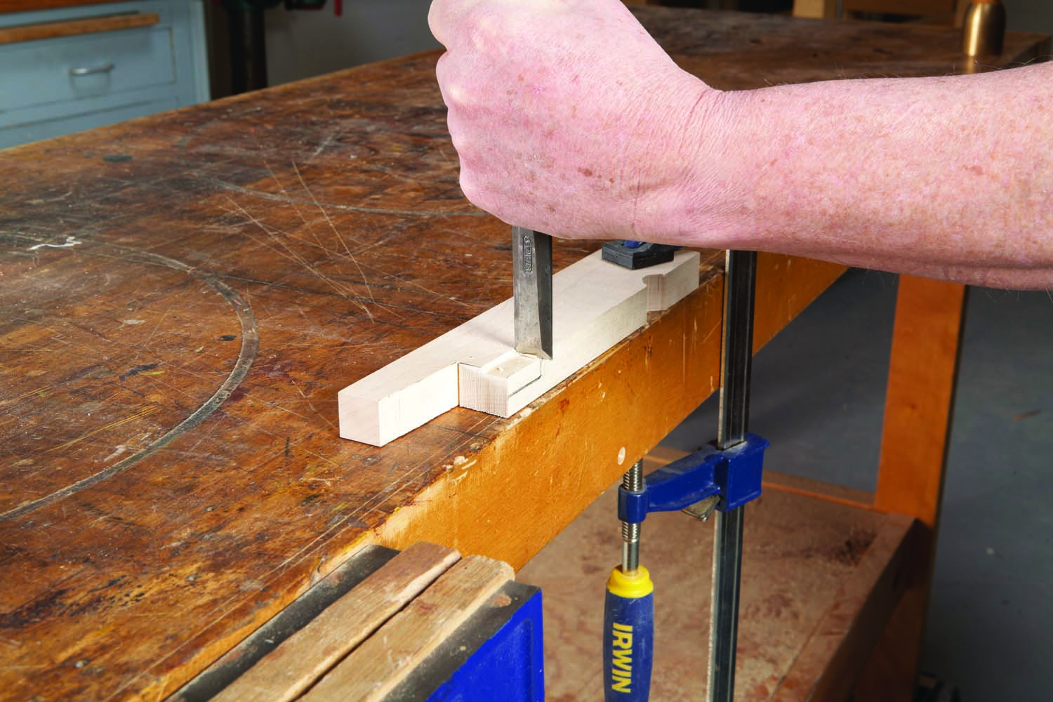
Photo 3. Chop a recess for the bandsaw’s sliding bracket. The bracket will rise into this recess as the blade is tensioned.
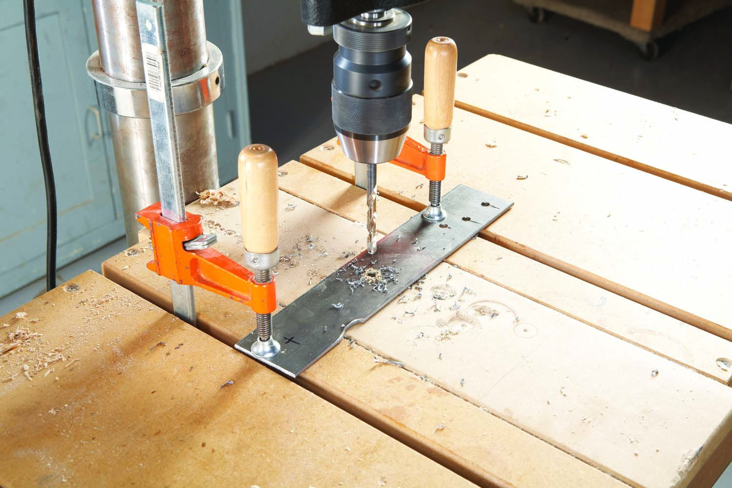
Photo 4. Drill three holes for attaching a steel plate (B1) to each riser block. Drill two holes for mounting the plates and riser blocks to the saw.
To make the stiffening plates, cut two pieces of flat steel the same length as the riser blocks. Cut or file the steel to match the profile of each riser block, then drill holes in the plates for attaching them to the riser blocks (Photo 4). Drill more holes for attaching the plates and riser blocks to the saw.
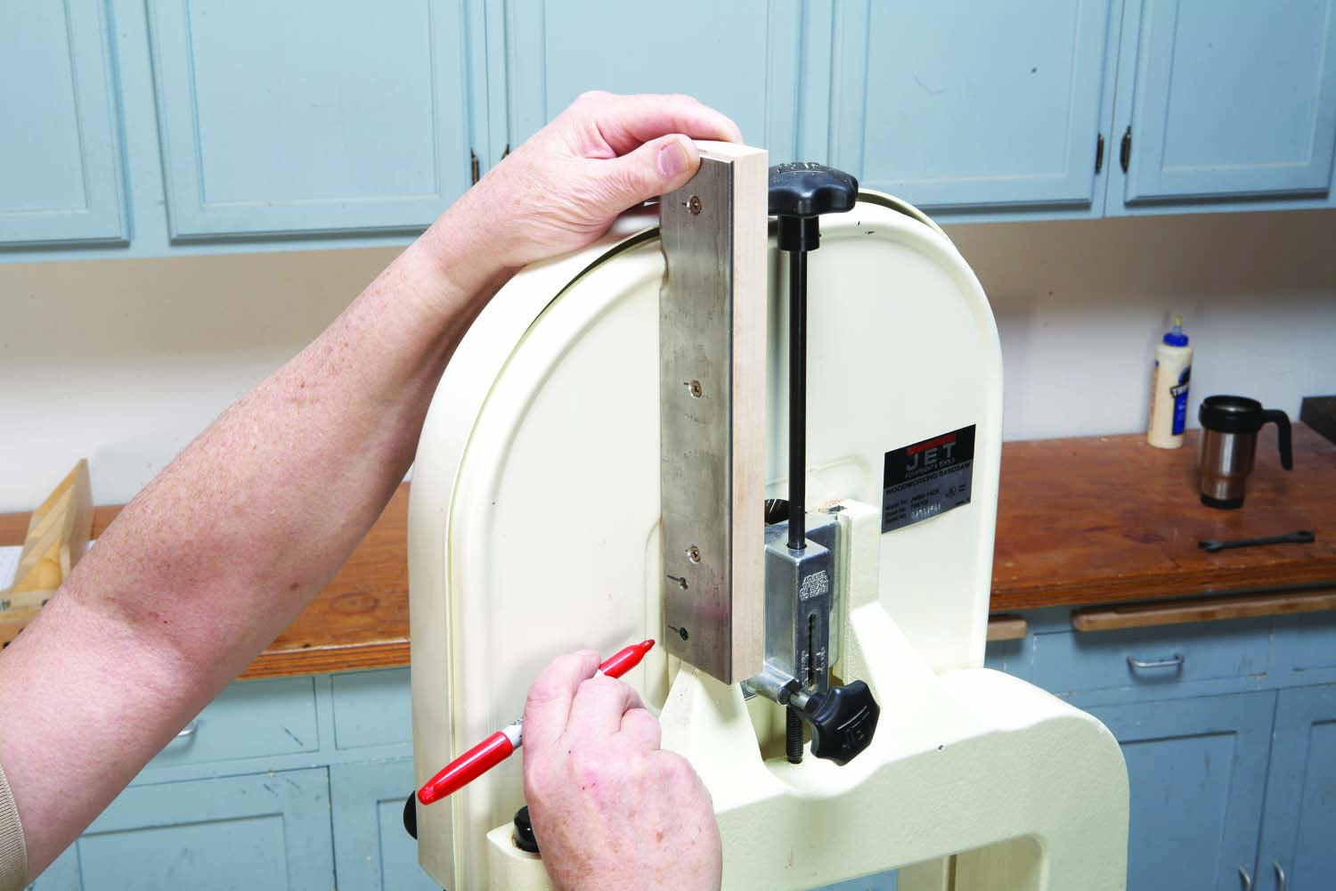
Photo 5. Fasten the plates to the riser blocks, then mark the location of the mounting holes on the saw.
Fasten the plates to the saw with screws (A2), then mark the location of the holes you’ll need to make for bolting the assemblies to the saw (Photo 5). Mark the holes with a center punch, then drill 1/8″ holes about 5/8″ deep. Enlarge the holes with a #8 bit (a 13/64″ bit will work OK, too), then tap the holes for 1/4-20 threads (Photo 6). Fasten the riser block/stiffening plate assemblies to the saw with bolts and washers (B2, B3). Note: the tops of the assemblies must be level with each other. If one sticks up higher than the other, remove and shorten it before you proceed.
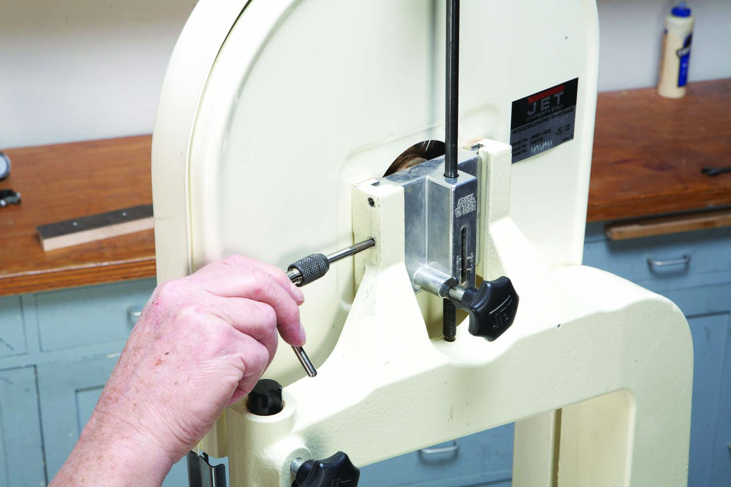
Photo 6. Drill and tap the mounting holes.
The air cylinder will sit on a mounting plate (C1), which is simply a piece of channel iron. You can order this channel iron precut to the length you need. Mark the center of the plate with a punch, then draw a 3-3/4″ dia. circle around the mark. Place the air cylinder over this circle, piston pointing up, and make sure you can see the circle through all four of the cylinder’s mounting holes. Clamp the cylinder to the plate. Drill holes through the plate for mounting the cylinder (Photo 7). After you drill the first hole, drop a cap screw (D1) through the hole to lock the cylinder in position for drilling the remaining holes.
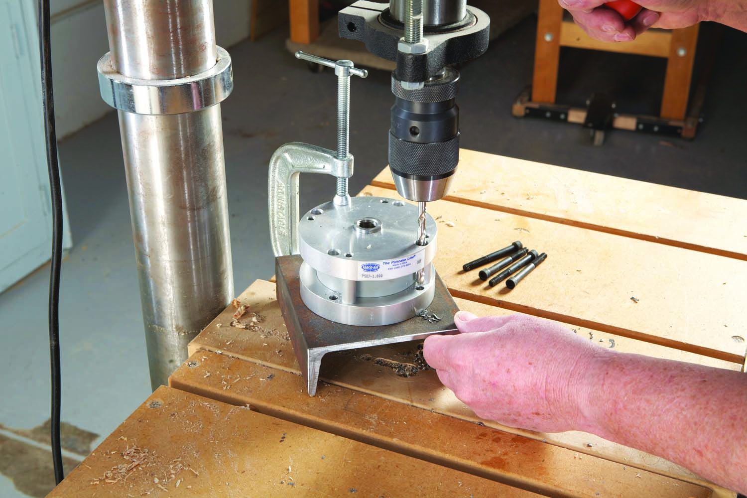
Photo 7. Center the air cylinder (L1) on a mounting plate (C1) made from channel iron. Drill holes for attaching the cylinder with cap screws (D1).
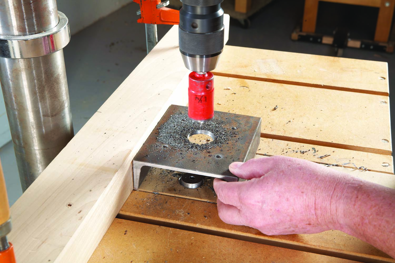
Photo 8. Drill a large hole through the mounting plate to accommodate the air cylinder’s piston. Fasten the cylinder to the plate.
Remove the cylinder and drill a 1/4″ hole through the center of the plate. Use this hole to guide a 1-1/4″ hole saw with bimetallic teeth, making a hole large enough to accommodate the air cylinder’s piston (Photo 8). Hold the plate against a fence, or clamp it to your bandsaw table, to make sure it doesn’t move as you drill. Drill two pairs of holes on the ends of the plate for mounting the plate on top of the riser blocks with lag screws (C2; see Fig. B). Paint the mounting plate and riser block assemblies to match your saw. Fasten the air cylinder to the plate with lock nuts (D2).
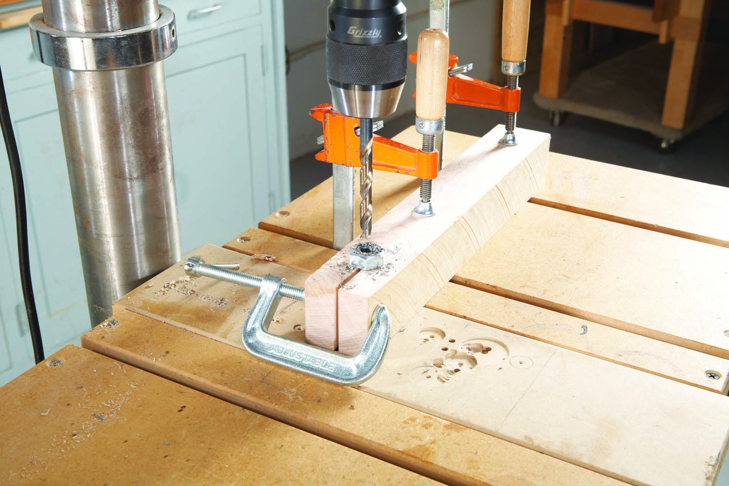
Photo 9. Drill a hole in the head of a short bolt (E1). This “adapter” bolt will connect the piston to a long all-thread rod.
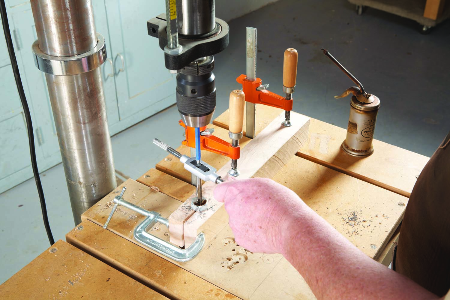
Photo 10. Tap the hole. Use the drill press to keep the tap vertical.
Next, make an “adapter bolt” (E1) for connecting the air cylinder’s piston to a 1/4-20 all-thread rod (F1). Use a 2″ thick block to hold the bolt for drilling and tapping (Photos 9 and 10). Drill a 5/8″ dia. hole near the end of the block, then use your bandsaw to cut a 1/4″ wide slot up to the hole. Place the bolt in the hole and clamp it. Use a #8 bit (or a 13/64″ bit) to drill a 1-1/2″ deep hole into the head of the bolt. Tap the hole for 1/4-20 threads, using the drill press and a prick punch to hold the tap vertical.
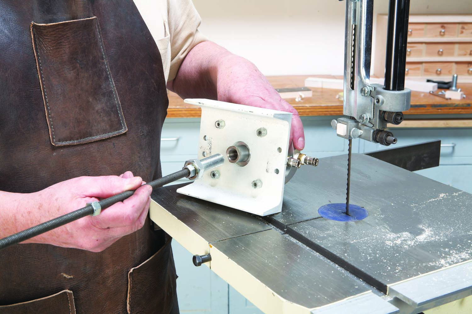
Photo 11. Thread the adapter bolt (E1) and all-thread rod (F1) into the air cylinder’s piston. Add two nuts (F2) to the rod.
Spin two nuts (F2) onto the all-thread rod. Position the first nut about halfway down the rod; position the second one about 2″ from the rod’s end. Turn this end of the rod into the tapped hole in the adapter bolt. Tighten the second nut against the head of the bolt. Thread the adapter bolt into the air cylinder’s piston (Photo 11).
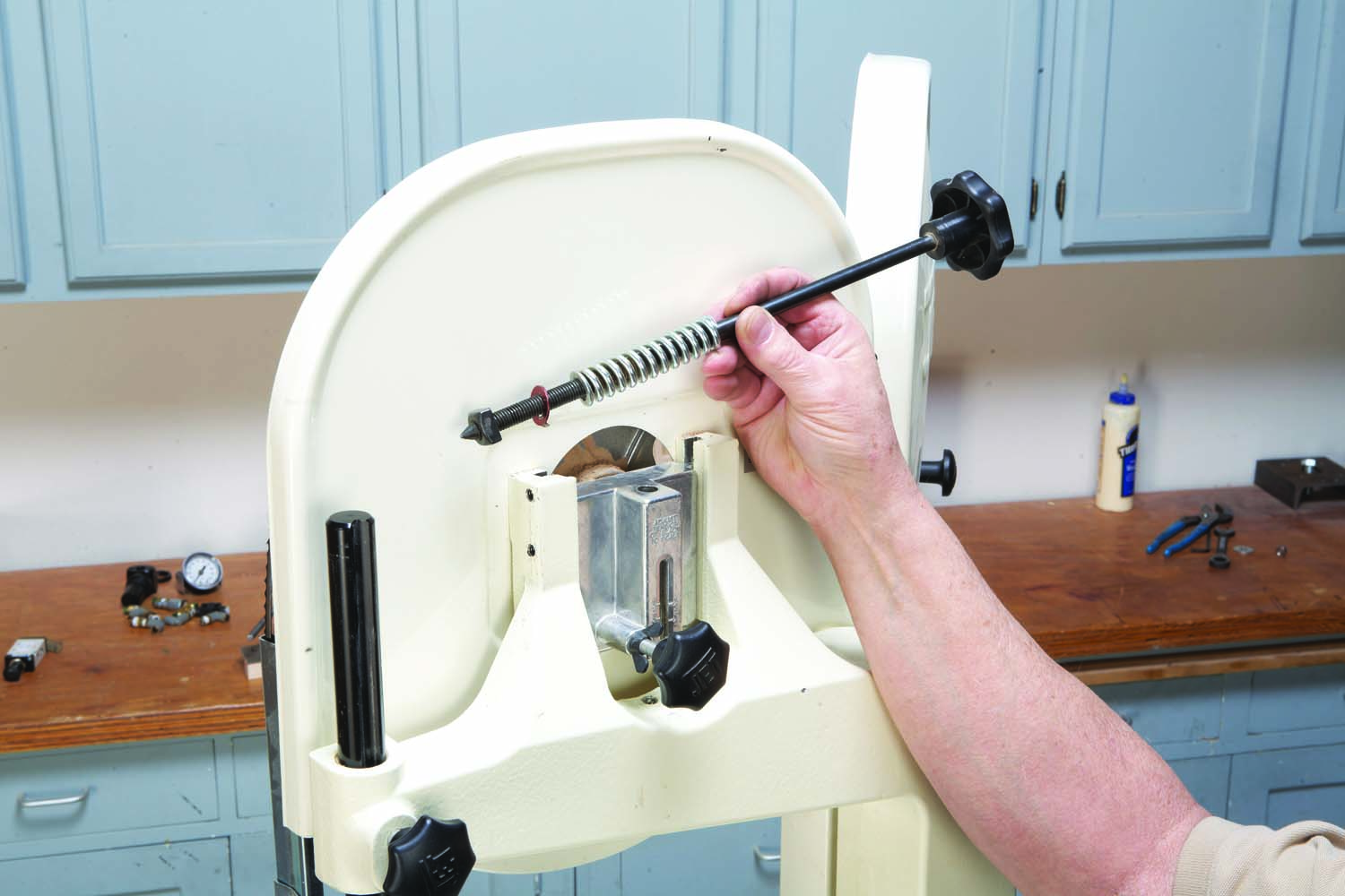
Photo 12. Remove the existing tensioning system from your saw. Unscrew these pieces and remove them separately.
Remove the old tensioning system from your saw (Photo 12). To do this, unscrew the adjusting bolt (the long rod with a knob on top). A square nut, red washer and spring will then fall out of the sliding bracket. Set all of these parts aside—you won’t need them for the new system.
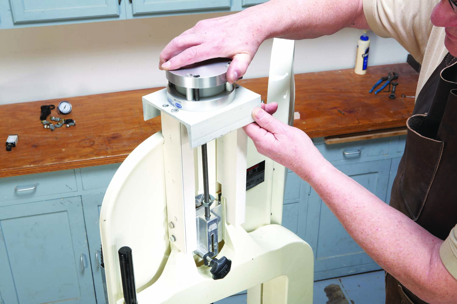
Photo 13. Fasten the riser block/stiffening plate assemblies to the saw, then position the mounting plate so the all-thread rod (F1) is vertical and centered in the sliding bracket.
Lower the all-thread rod into the sliding bracket (Photo 13). Rest the air cylinder’s mounting plate on top of the riser blocks. Adjust the plate’s position so the rod is plumb and centered in the sliding bracket. Mark the position of the plate’s mounting holes on the tops of the riser blocks, then drill holes into the riser blocks for the lag screws. Insert and tighten the lag screws (Photo 14).
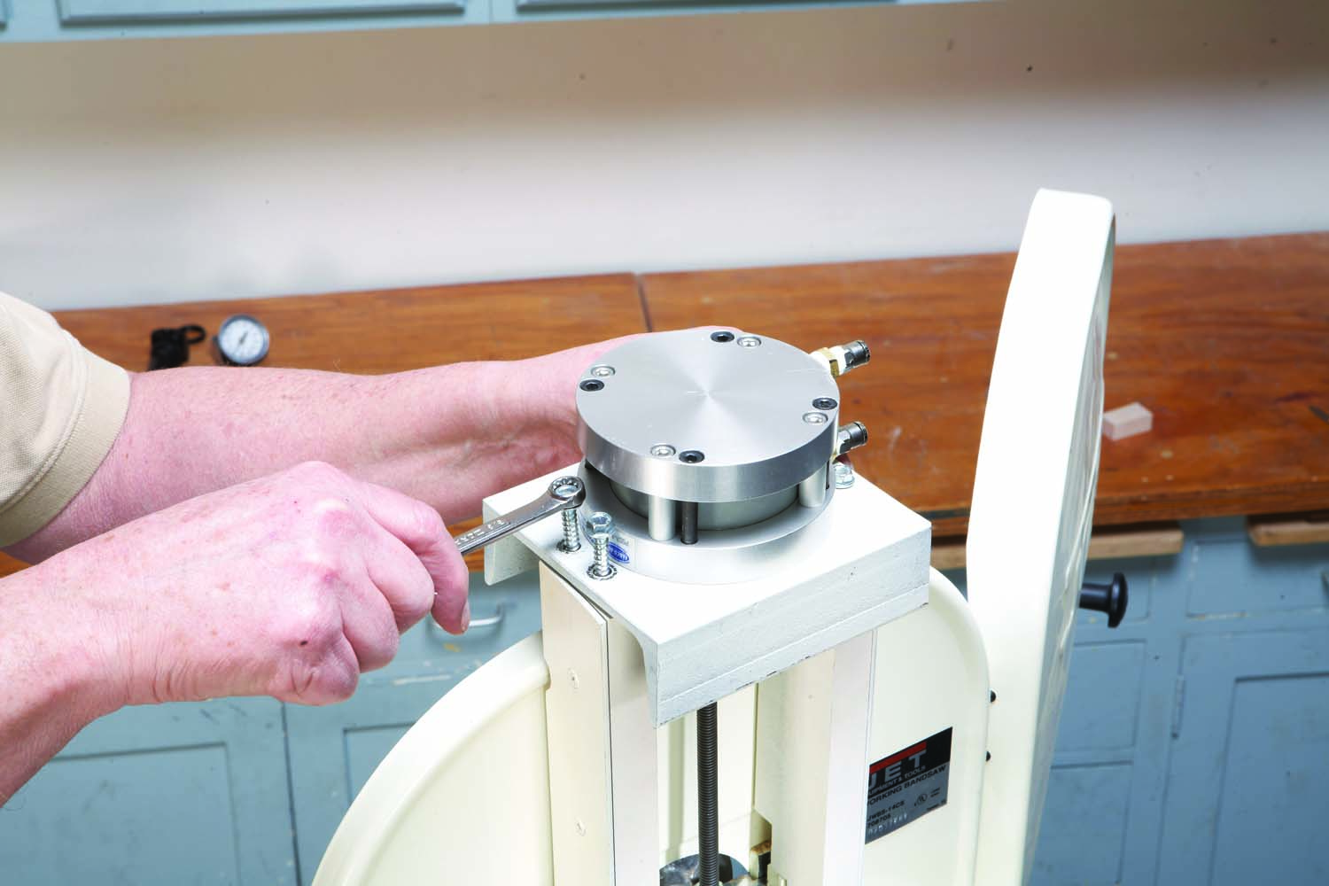
Photo 14. Fasten the mounting plate to the riser assemblies with lag screws (C2). Add a washer and nut to the end of the rod, then tighten the nut against the sliding bracket.
Holding onto the rod, pull the piston out of the cylinder and push it back in half way. Turn the nut in the middle of the rod until it comes into contact with the top of the sliding bracket. Place a flat washer (F3) over the bottom of the rod and thread on a nut. Tighten the nut against the bottom of the sliding bracket.
Place a spring (F4) under the nut on the bottom of the rod. The spring will prevent the sliding bracket from sliding down too far when you relax the tension on the blade. This completes the tensioning mechanism.
Pneumatic Parts
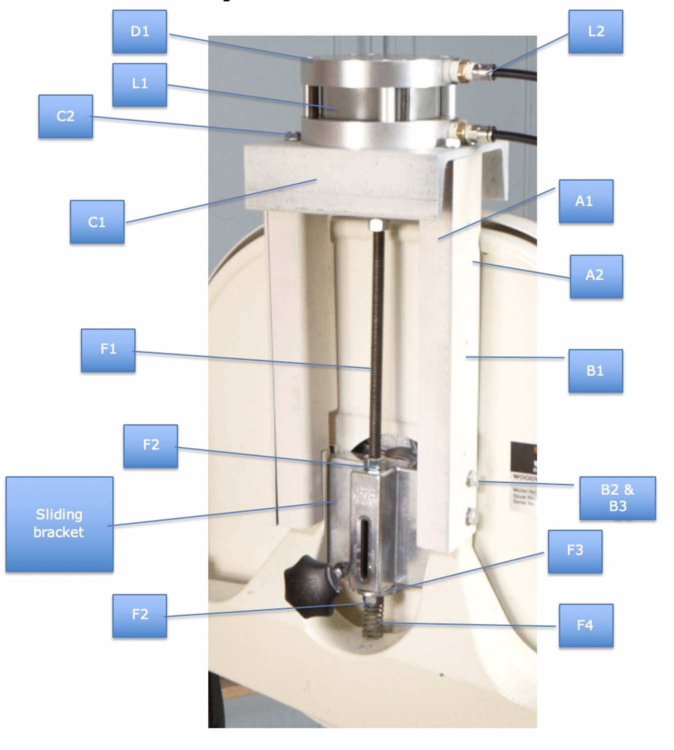
Fig. A. Bandsaw Hardware 1
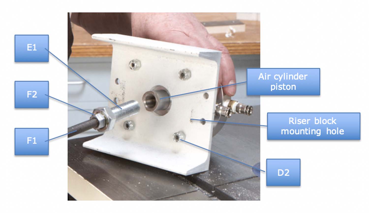
Fig. B. Bandsaw Hardware 2
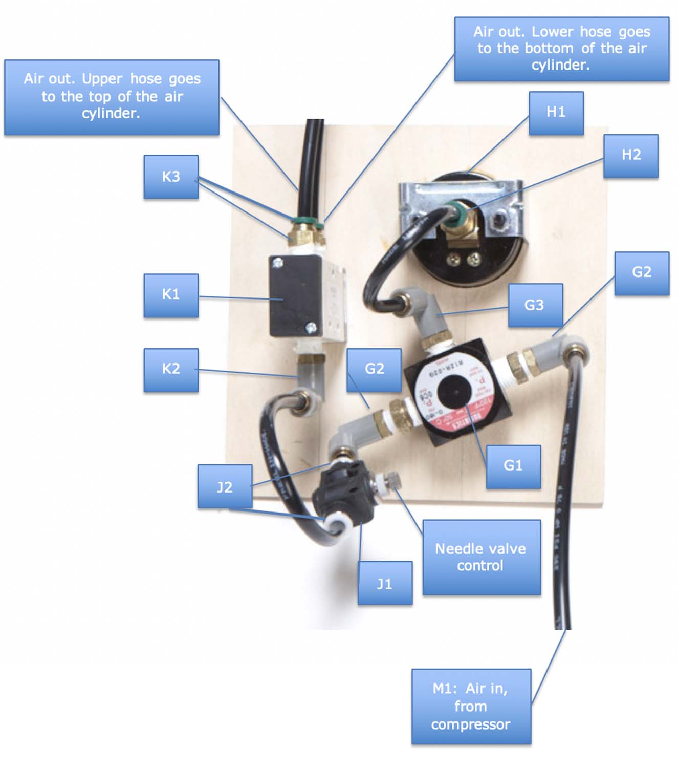
Fig. C. Pneumatic Parts Inside Control Box
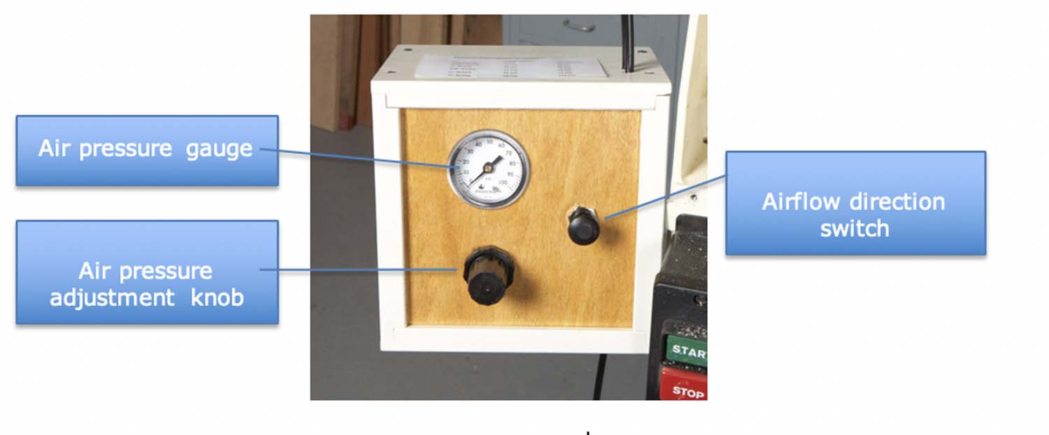
Fig. D, The Control Box
| Part | Name | Qty. | Specs | Source, Part No., Price (ea.) |
| G1 | Air regulator | 1 | JHF, Numatics R12R-02G, | |
| G2 | ” ” fitting | 2 | 1/4″ NPT, 90° push-in | McMaster-Carr, 51025K137, $4.07 |
| G3 | ” ” fitting | 1 | 1/8″ NPT 90° push-in | McMaster-Carr, 51025K136, $3.65 |
| G4 | ” ” nut | 1 | JHF Numatics PN12, | |
| H1 | Air gauge | 1 | 2″, panel mount, 0-100 PSI, 1/8″ NPT | McMaster-Carr, 3846K451, $14.84 |
| H2 | ” ” fitting | 1 | 1/8″ female, push-in | McMaster-Carr, 51025K243, $2.39 |
| J1 | Needle valve | 1 | 1/4″, single-direction flow control | McMaster-Carr, 7824K12, $30.76 |
| J2 | ” ” fitting | 2 | 1/4″ NPT straight, push-in style | McMaster-Carr, 51025K178, $1.98 |
| K1 | Air valve | 1 | 1/4″ NPT, 5-port, 2-position | JHF, MFD Pneumatics M4L310-08, |
| K2 | ” ” fitting | 1 | 1/4″ NPT, 90° push-in | McMaster-Carr, 51025K137, $4.07 |
| K3 | ” ” fitting | 2 | 1/4″ NPT straight, push-in style | McMaster-Carr, 51025K178, $1.98 |
| L1 | Air cylinder | 1 | 3″ Dia. piston with 1″ stroke | McMaster-Carr, 4208K48, $111.88 |
| L2 | ” ” fitting | 2 | 1/4″ NPT straight, push-in style | McMaster-Carr, 51025K178, $1.98 |
| M1 | Tubing | 25′ | 1/4″ OD, nylon, black | McMaster-Carr, 5548K65, $.44/ft. |
| N1 | Compressor fitting | 1 | 1/4″ NPT straight, push-in style | McMaster-Carr, 51025K178, $1.98 |
| Sources: JHF, jhfoster.com, 800-582-5162; McMaster-Carr, mcmaster.com, 630-833-0300. | ||||
Bandsaw Hardware
| Part | Name | Qty. | Material | Dimensions |
| A1 | Riser block | 2 | Painted hardwood | 3/4″ x 2″ x 10-1/2″ |
| A2 | ” screws | 6 | Flat head screw | 1″ #6 |
| B1 | Stiffening plate | 2 | Steel | 1/8″ x 2″ x 10-1/2″ |
| B2 | ” ” bolt | 4 | Bolt | 1/4-20 x 1/2″ |
| B3 | ” ” washer | 4 | Lock washer | 1/4″ |
| C1 | Mounting plate | 1 | Channel iron | 5″ wide x 5-1/2″ (b) |
| C2 | ” ” screws | 4 | Lag screw | 1/4″ x 1-1/2″ |
| D1 | Air cylinder screw | 4 | Socket head cap screw | 1/4-20 x 3″ |
| D2 | ” ” nut | 4 | Lock nut | 1/4-20 |
| E1 | Adapter bolt | 1 | Grade 5 bolt | 5/8-18 x 2″ |
| F1 | Rod | 1 | All-thread rod | 3/8″ x 12″ |
| F2 | ” nut | 3 | Nut | 3/8-16 |
| F3 | ” washer | 1 | Washer | 3/8″ |
| F4 | ” spring | 1 | Spring | 5/8″ OD x 1-1/2″ |
| Notes: (a) The part dimensions given in this chart are only for a Jet bandsaw. Your bandsaw may require parts of different lengths and widths. (b) | ||||
Install the pneumatics
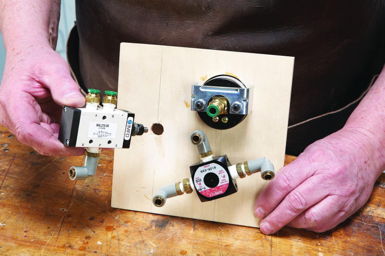
Photo 15. Build a box to hold the components that will regulate the flow of air to the cylinder. Mount the components to a plywood panel.
Build a wooden box to hold the pneumatic controls. Mine is 8″ wide by 8″ tall by 6″ deep. It has a removable top and a front panel that slides in from above for easy access to the components inside. Drill one 15/64″ dia. hole in the bottom of the box, for air in, and two similar holes in the top of the box, for air out. Also, make a bracket for securing the box to your saw. Mine is made from flat steel stock, bent at an angle and bolted to the saw. Fasten the box to the bracket.
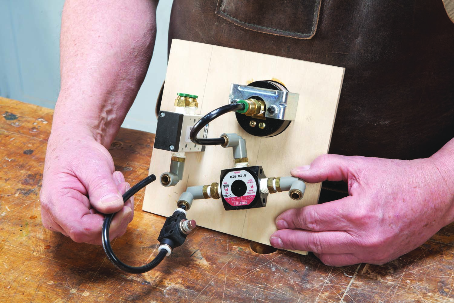
Photo 16. Add a needle valve, then connect the components with tubing. All you have to do is push the tubing into each fitting.
Drill holes in the panel for an air regulator (G1), air gauge (H1) and air valve (K1). Gather the fittings you’ll need, then wrap Teflon tape around their threads and screw them into the components (Fig. C). Install the components on the panel (Photo 15). Connect a needle valve to the air regulator, then cut short lengths of nylon tubing (M1) to connect the components (Photo 16). The ends of the tubing must be cut square, but all you have to do to install them is to push them into the fittings.
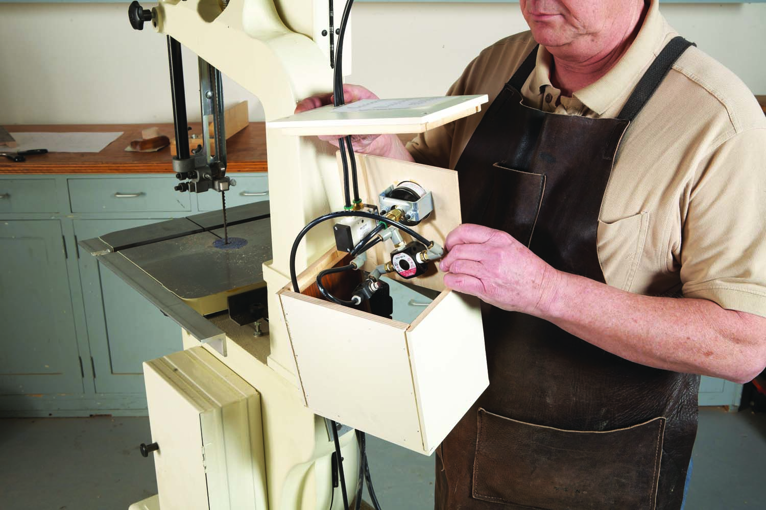
Photo 17. Slide the panel into the box, which is fastened to the bandsaw. Add a lid on top of the box.
Cut two pieces of tubing to go from the box to the air cylinder. Connect them to the air valve (Fig. C). Cut another piece of tubing to go from the box to your air compressor. Connect this tubing to the air regulator. Run the tubing through the holes in the box, then slide the front panel and top of the box into place, but don’t fasten the top yet (Photo 17).
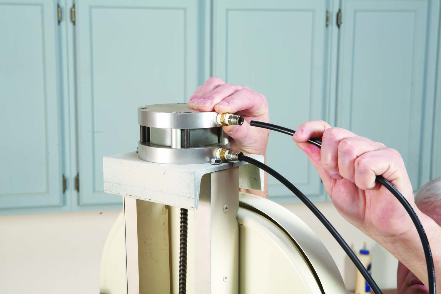
Photo 18. Connect two lines to the air cylinder. The lower one pushes the piston up, for tensioning; the upper one pushes the piston down, for relaxing the tension.
Install fittings in the air cylinder, then hook up the tubing (Photo 18). Install a fitting on the hose that goes to your compressor, then thread the fitting into a second, larger fitting—one that fits your particular type of compressor. Turn the air regulator knob counterclockwise, all the way, to deliver the least amount of air to the cylinder. Also, push in the airflow direction switch on the front of the control box (Fig. D).
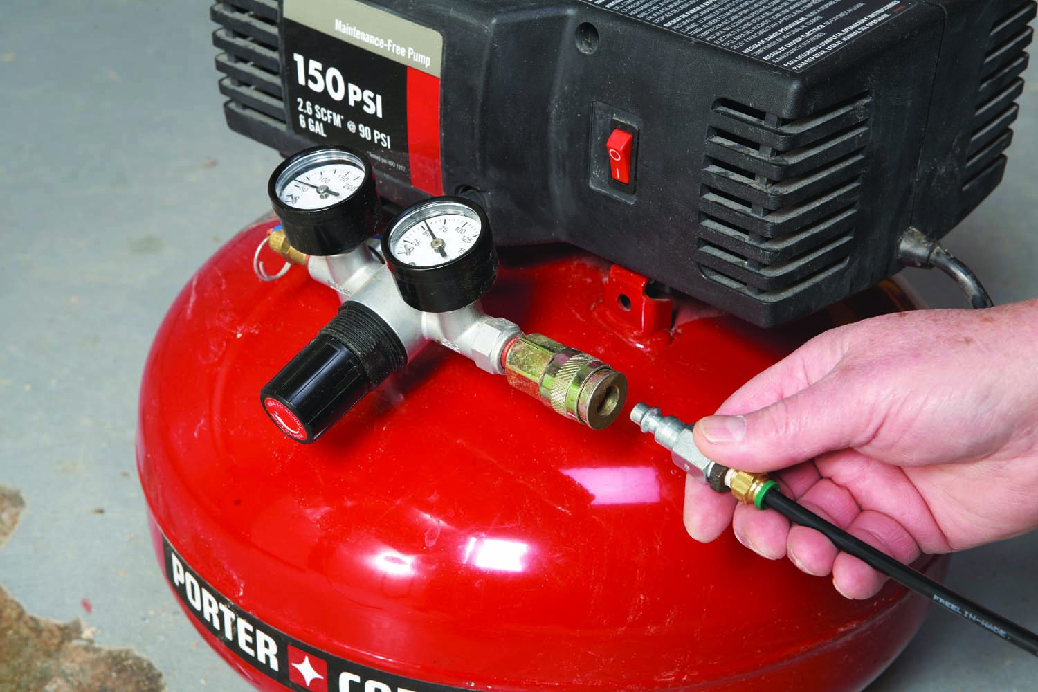
Photo 19. Attach a line to your compressor. A small compressor will work fine—this system doesn’t require a large volume of air.
Connect the tubing to the compressor and turn it on (Photo 19). Adjust the compressor to deliver 100 psi. Turn the air regulator knob to gradually increase the amount of air flowing to the cylinder. The piston, rod and sliding bracket should move up; if they move down, reduce the air pressure to zero and switch the hoses that run to the air cylinder. Adjust the rate at which the piston moves (slow is better than fast) by turning the needle valve (Photo 20). Assemble the control box.
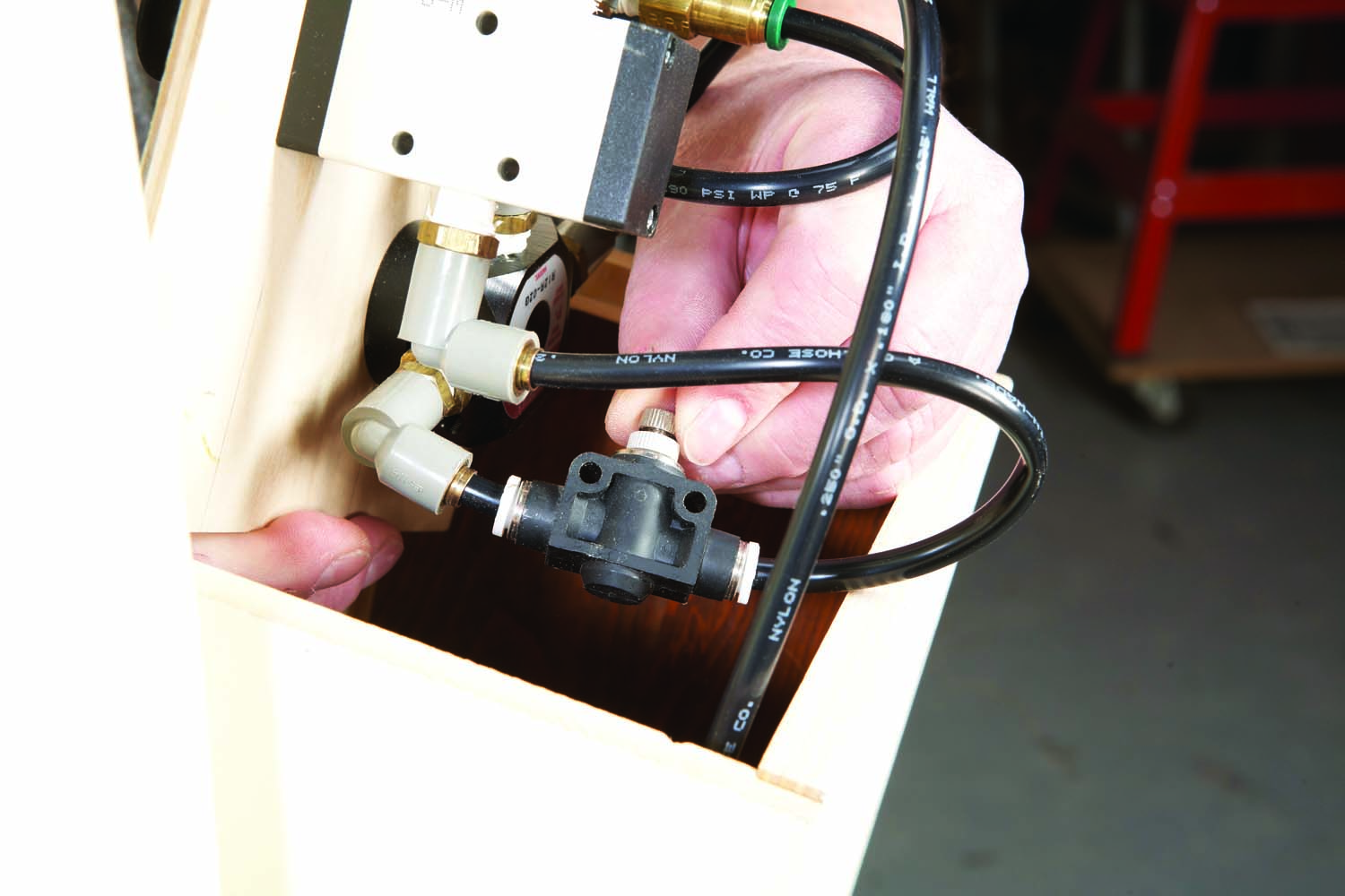
Photo 20. Turn on the compressor and adjust the needle valve. This valve controls the rate at which the piston moves up or down.
To fine-tune the air mechanism, increase the air pressure to the amount appropriate for your blade (Photo 21). At this point, the air cylinder’s piston should extend about halfway out. If it isn’t, reduce the air pressure to zero and adjust the nuts on the all-thread rod.
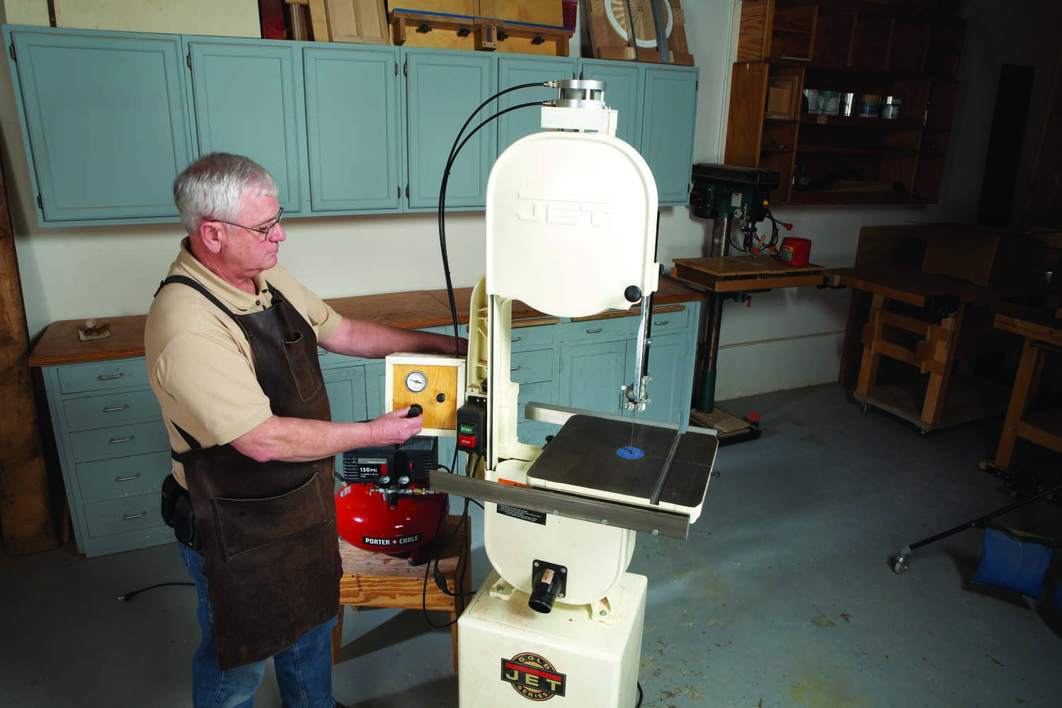
Photo 21. Adjust blade tension by increasing or decreasing air pressure. This system is quiet, precise and easy to operate.
In order to change blades, pull out the airflow direction switch. Air pressure will now push the piston down, removing all tension from the blade.
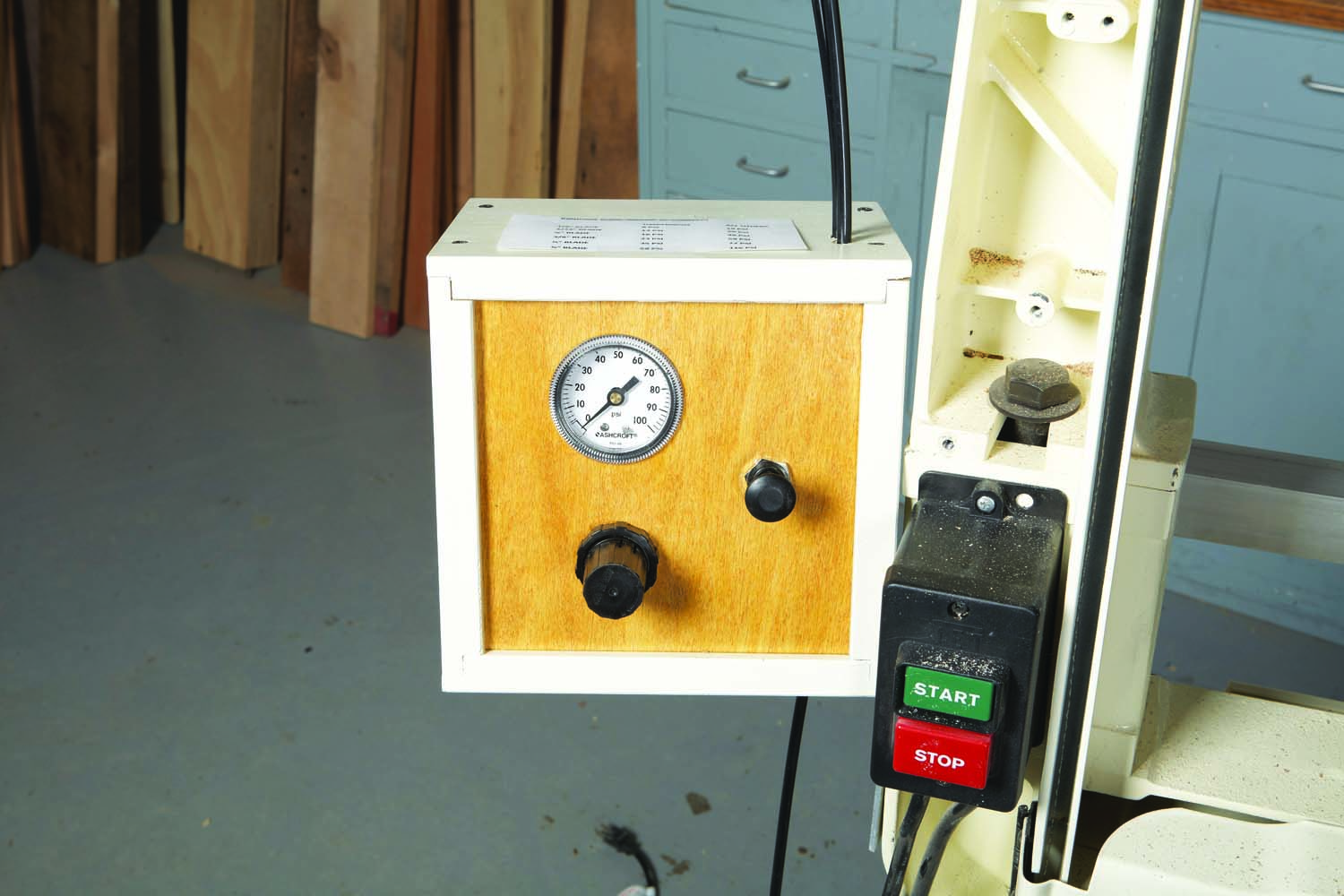
Tensioning by the Numbers
By converting your tensioning system to air pressure, you can precisely adjust the amount of tension on your blade simply by turning a knob and reading a gauge. Both are conveniently located on a control box next your saw.
The knob adjusts the amount of air pressure; the gauge tells you what it is. Using a conversion chart taped to the top of the box, you can easily tell how much pressure is necessary for a particular blade.
The amount of pressure you’ll need depends primarily on the blade’s thickness and width, but it also depends on the type of alloy that the blade is made from. The numbers given in the chart below, then, are just guidelines. You may find that more or less pressure is needed for your favorite blade.
Once you find the ideal amount of tension for your blade, record the amount of air pressure it required. Every time you change blades, or put on a new blade, you’ll be able to dial in the proper amount of tension quickly and easily.
|
Blade Tension in PSI* |
||
|
Blade Width |
Silicon Steel Blades |
Other Blades |
|
1/8″ |
6 |
14 |
|
3/16″ |
8 |
21 |
|
1/4″ |
10 |
25 |
|
3/8″ |
17 |
43 |
|
1/2″ |
27 |
60 |
|
3/4″ |
50 |
100 |
|
* For 3″ dia. air cylinder |
||
Here are some supplies and tools we find essential in our everyday work around the shop. We may receive a commission from sales referred by our links; however, we have carefully selected these products for their usefulness and quality.


