


We may receive a commission when you use our affiliate links. However, this does not impact our recommendations.
Creative thinking and dirt-simple jigs make the joinery a straightforward task.
Full-Size Plan: Download
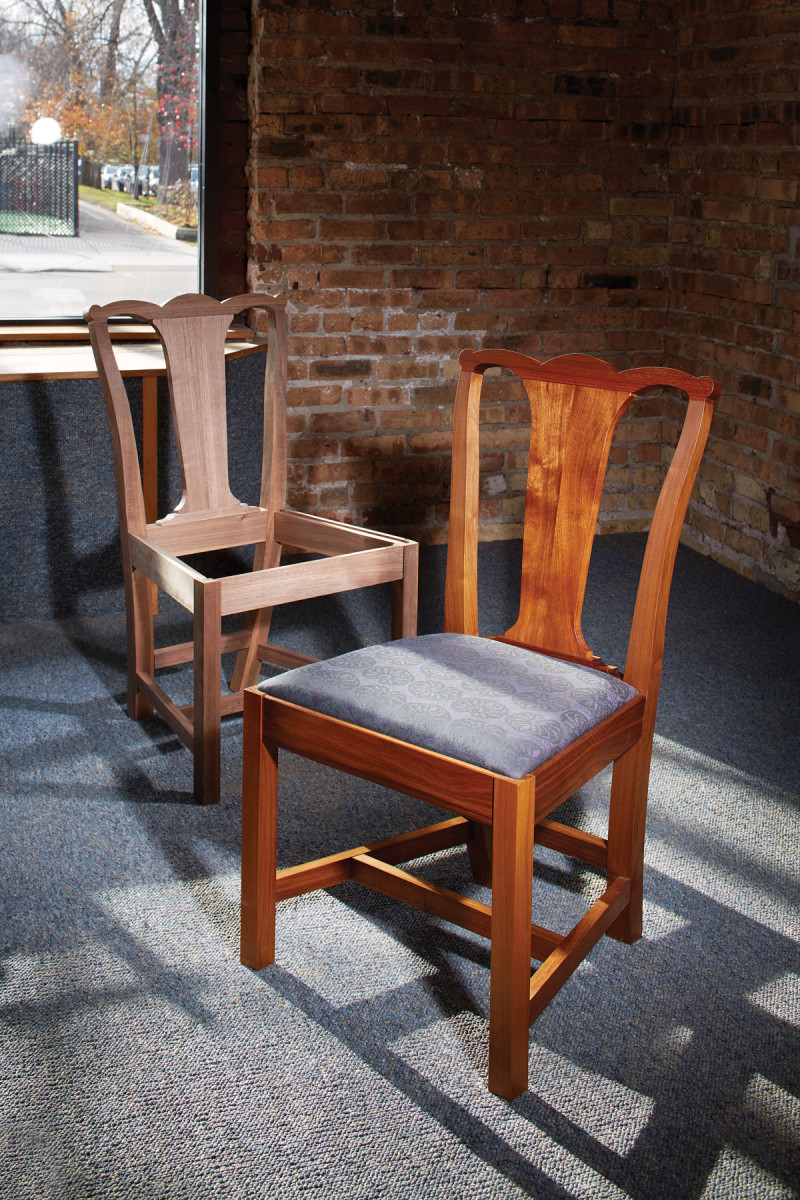
I tend to think of Chippendale chairs as highly ornate. But there are startlingly simple examples of the style as well. After encountering some of the simpler versions of these chairs, I became fascinated. I love the interplay of curves and angles, the simple yet bold form and the feeling that this chair could fit in almost anywhere. So I decided to build my own moderately faithful version.
Interestingly, the joinery found on the originals is in some ways easier to execute by hand. Using some tools and processes about which I’ve written before, along with some simple additions, cutting accurate joinery is easy and reliable. This article will focus on that joinery and how to make it simple to execute by hand.
Features of the Chair
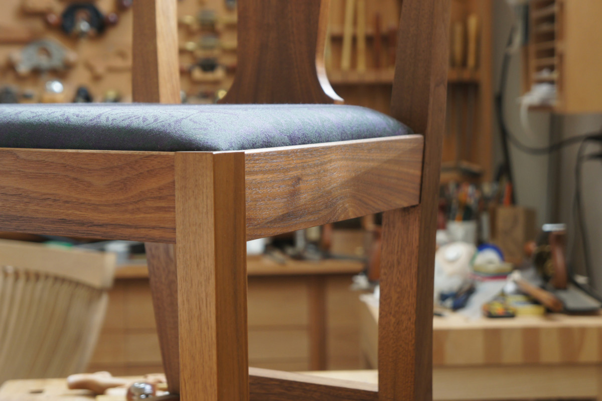
Twisted side rails. The splayed back legs are an obvious feature of this chair style. Less obvious is the twist in the side rails that accommodates the splay of the back legs. In most circumstances, this feature is invisible. But in the right light, it appears like magic.
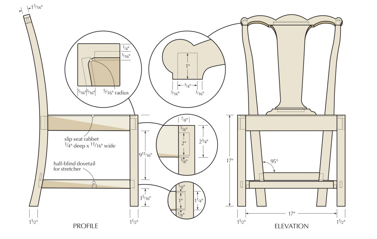
The most notable design features of this chair – and most chairs in the Chippendale style – are the splayed and curved back legs and the twisted side rails and stretchers. There are also the “ears” that provide some additional material in the crest rail for the joint with the rear legs.
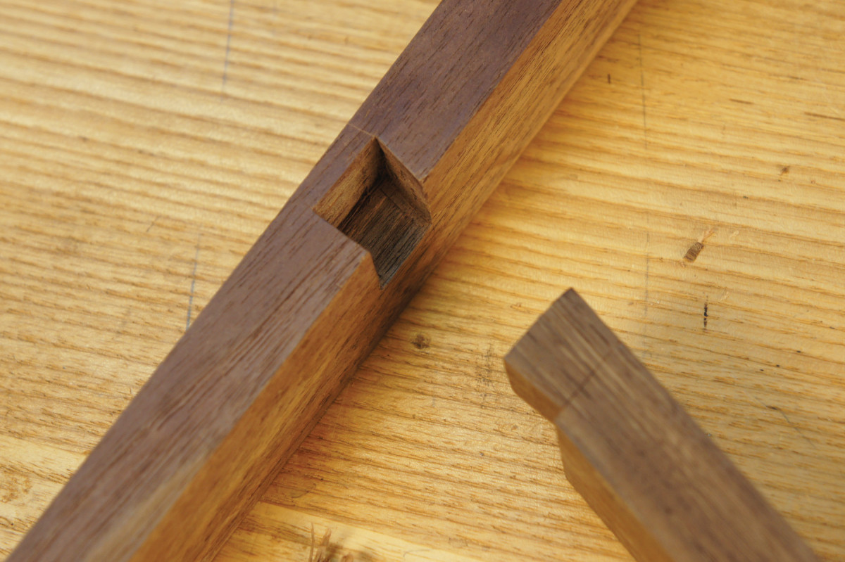
Structurally, the most interesting elements are the angled mortises and straight tenons with angled shoulders found on the side rails and side stretchers. These are not much harder to cut by hand than an ordinary mortise-and-tenon joint, but grow in complexity when cut by machine. The splay of the legs comes from the angled shoulders (from top to bottom) of the back rail – these, too, are easily cut by hand, but aren’t much harder by machine.
On Building Chairs
Chairs are complex. You should approach them differently than other projects. Although there are plans included here, chairs are not generally built from plans. You’re better off with patterns.
Chair patterns work like story sticks, in that they not only have the information about the shaping and sizing of curved parts, they also contain information about the joinery on these parts. You should also work through most of this chair project without paying attention to specific angles. This chair does have one exception to this: the angles at both ends of the lower back rail should be 5°. Because this angle only becomes critical once you’ve chosen it, a protractor is fine for setting your bevel for this angle. The length of this rail (at the top) is 12″.
All other angles and lengths should come directly from the chair itself as the project progresses.
The Back Legs
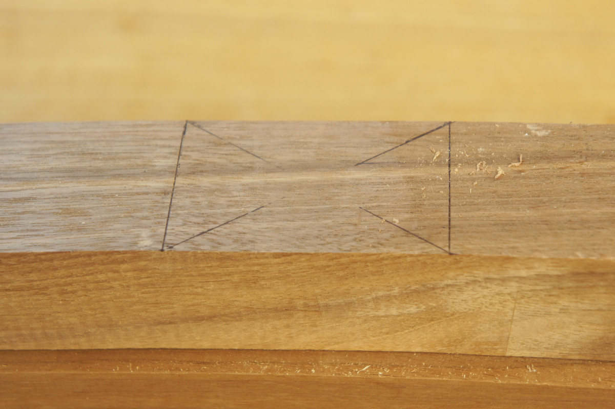
Make a flat place. The first passes are to plane away the center of the X. Plane away the legs of the X evenly until they disappear and then take another pass or two.
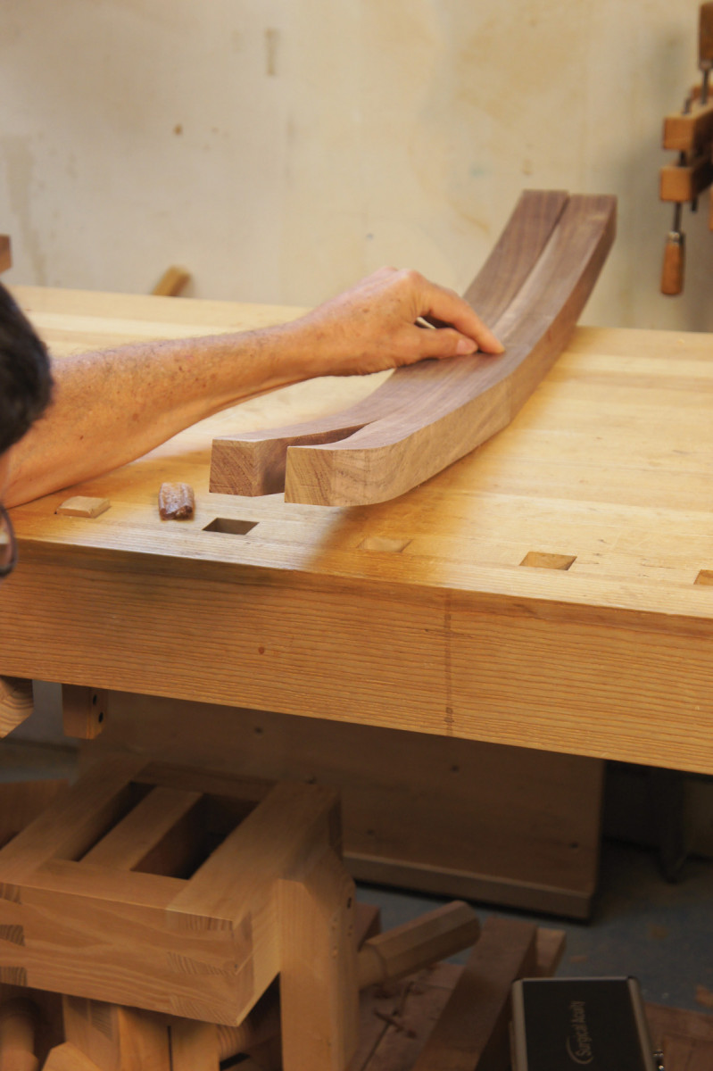
Start work by making two patterns for the back legs and lay out this profile on the backs of the two legs. Cut the profile and smooth the convex and concave curves.
Lay out the flat section on the front of the legs where the side rails will join the legs. Mark an X from opposite corners. Plane the center of the X until you reach the limit lines of the flat section.
The Front Legs
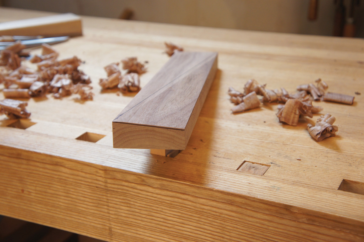
Mill the front legs 1″ overlong for now. You’ll cut the extra off after mortises have been chopped and the tenons fit.
Now lay out the locations for the side rail, front and lower back rail mortises. Lay out 1⁄4“-wide mortises for now; you’ll re-scribe and pare to the 5⁄16” finished dimension after chopping. Additionally, lay out the mortises for the lower back stretcher.
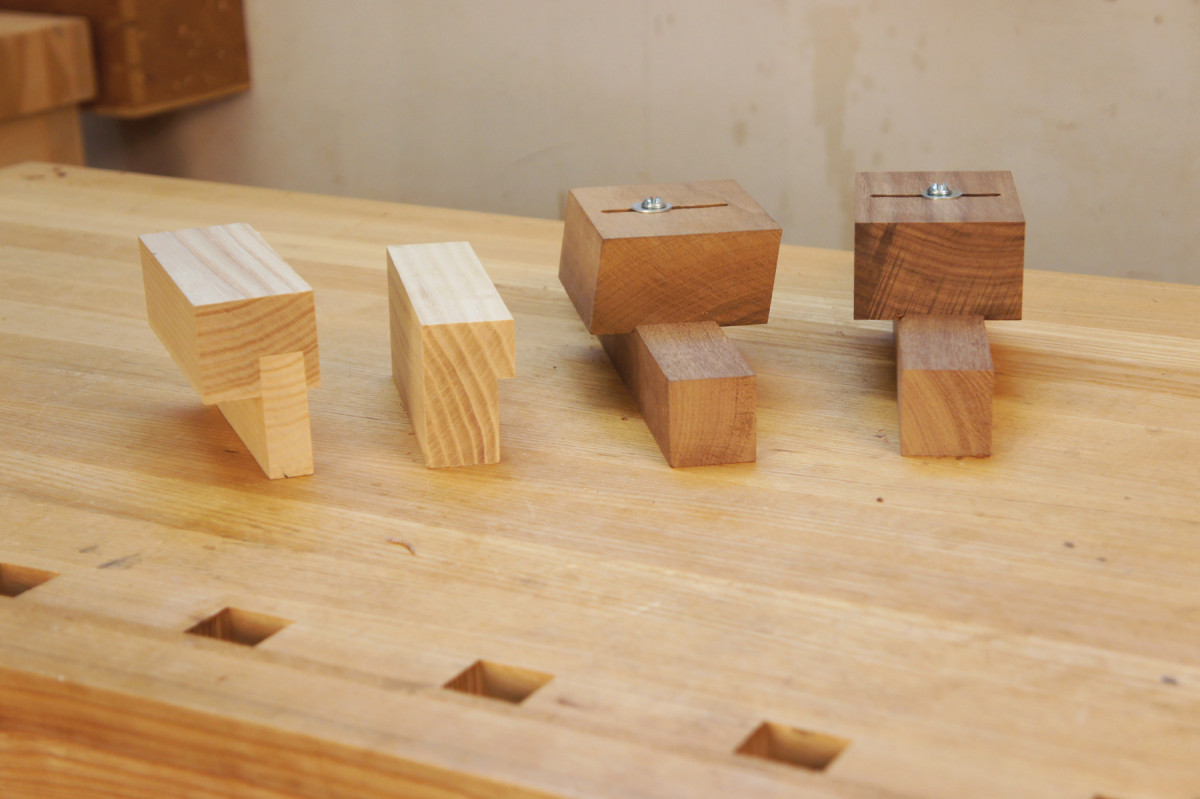
Not Quite 31 Mortise Flavors
There are lots of different mortise-and-tenon joints in this chair:
■ Basic joints (front rail to the front legs, crest rail)
■ Joints where the mortise is the same as in a basic joint but the tenon has an angled shoulder (lower back rail to the back legs and lower back stretcher)
■ Joints where the mortise is cut at an angle to the surface, the tenon is cut parallel to the rail but the shoulders are angled (side rail to leg joints)
■ And variations on these flavors where the tenons have only one shoulder (the side and back stretchers).
A few simple jigs make the mortising easier. They are quick to build, and they produce accurate results when used with sharp chisels.
Chopping & Paring
Are you flat? Check that the flats on the two legs are the same by placing the legs with the planed flats on a flat surface. The tops of the legs should be the same height off the surface. The leg bottoms don’t matter as much.
On all of the chair mortises, I chop first, then pare with the chisel held tight to a paring block. After the first paring cut, slide the chisel over about 1⁄8” and make the next cut with the tool’s leading edge. Overlapping cuts require less force, and this leads to greater accuracy.
Chippendale Chair Cut List
No.ItemDimensions (inches)MaterialComments
t w l
❏ 2 Front legs 1 1⁄2 x 1 1⁄2 x 18 Rift Walnut Rough length*
❏ 2 Back legs 1 3⁄4 x 4 1⁄4 x 39 Walnut Oversized**
❏ 2 Side rails 1 x 2 3⁄4 x 17 Walnut Rough length
❏ 1 Front rail 1 x 2 3⁄4 x 20 Walnut Rough length
❏ 1 Rear rail 1 3⁄8 x 2 3⁄4 x 15 Walnut Rough length
❏ 2 Side stretchers 1 1⁄16 x 1 3⁄8 x 17 Walnut Rough length
❏ 1 Center stretcher 11⁄16 x 1 3⁄8 x 17 Walnut Rough length
❏ 1 Rear stretcher 11⁄16 x 1 3⁄8 x 13 Walnut Rough length
❏ 1 Crest rail 1 3⁄16 x 2 1⁄8 x 22 Walnut Rough length
❏ 1 Shoe 1 1⁄4 x 1 x 12 Walnut Rough length
❏ 1 Back splat 3⁄4 x 4 x 18 Walnut †
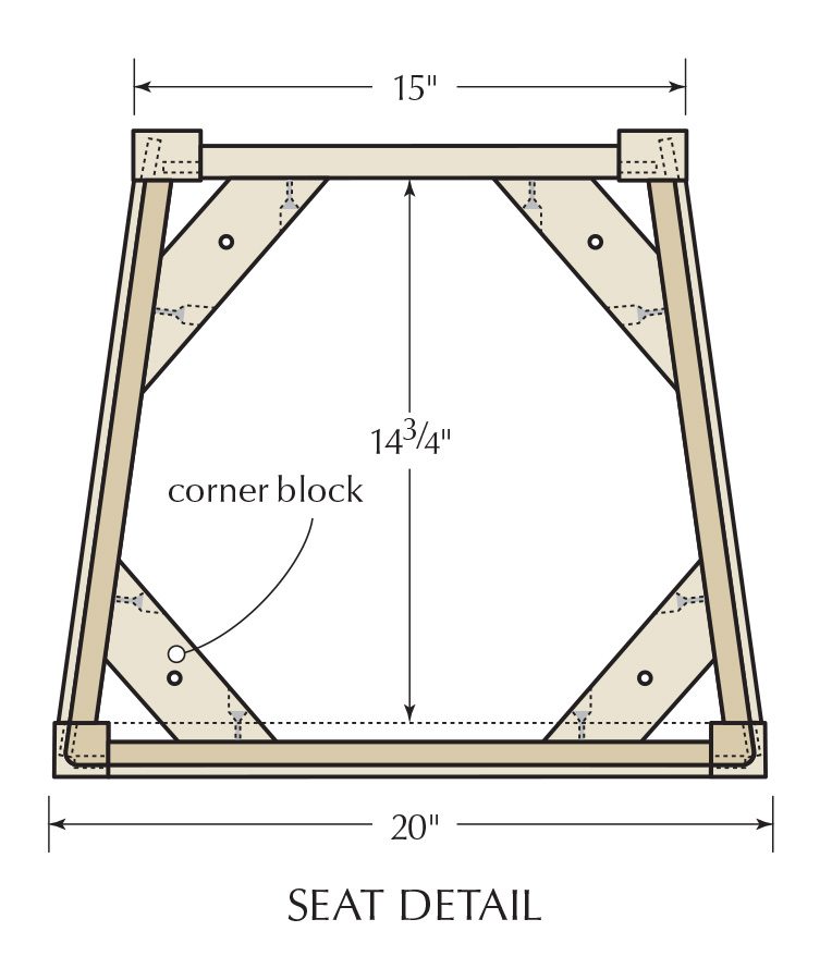
❏ 1 Corner block blank 1 x 2 1⁄2 x 24 Hardwood ‡
❏ 1 Slip seat 3⁄8 or 1⁄2 x 16 x 20Plywood
*Parts should be fit and trimmed in place. **Can be nested and pulled from one 6″-wide board. †Two matched pieces or one wide board. ‡Rough length of total stock needed for 4 corner blocks.
Editor’s note: As Jeff notes above in “On Building Chairs,” the angles and lengths used to build this chair should be determined through the process of construction. Measurements have been supplied for reference, and correspond to Jeff’s full-sized drawings.
Plain Vanilla Mortises
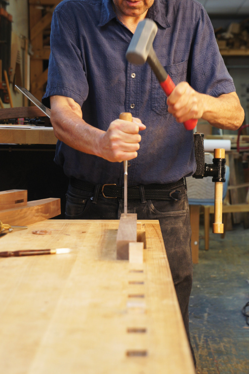
In line with the back. The setup on your bench is important to the success of mortising. Make sure you can see that you’re holding the chisel vertical (or angled appropriately).
The least intimidating mortises on the chair are those on the inside faces of the front legs. Follow these with the mortises for the lower back rail in the rear legs. Chop them perpendicular to the front surface of the legs.
Scrap support. When you chop the mortises in the back legs, you’ll want to support the legs against the pounding. Use the offcut from band sawing the leg.
The smaller mortises for the lower back stretcher are also “vanilla.” Pare all of the side walls using the paring blocks. Although the mortises in the crest rail are also simple, wait until you’ve dry-assembled the back rail and the two back legs to lay them out.
More Interesting Flavors
The easy way. You can do it the hard way, or you can do it the easy way. All of these jigs make it easier to get great results.
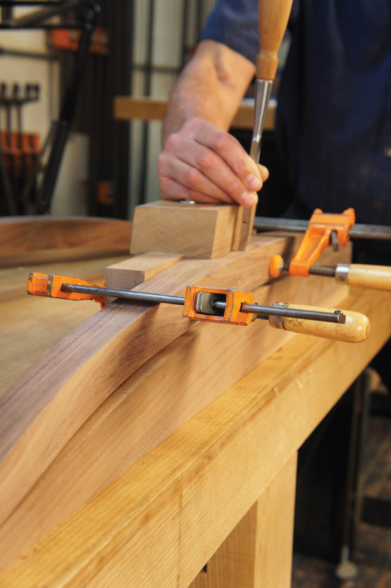
Chopping the angled mortises for the side rails (in the front and back legs) is similar to the straight mortises. The easiest way to deal with the angles is to rely on the angled paring block as a chopping guide. Keep the chisel about 1⁄32” away and watch the gap between the block and the chisel. Any inaccuracy will get pared away.
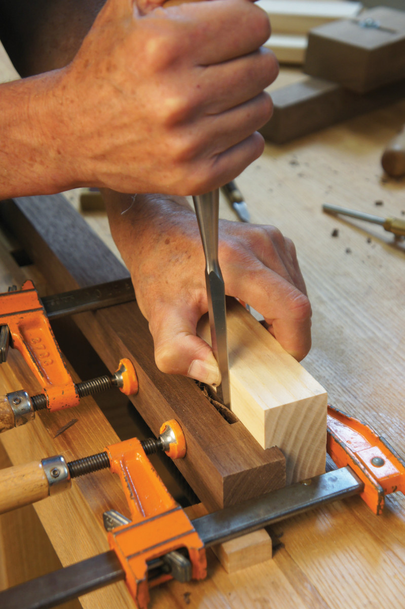
A block guides you. Pare the side walls to final size. Most of the time I use a paring block, and stagger my paring cuts.
Don’t cut the angled mortises for the stretchers yet. These are not at the same angle as the side rail angle. You’ll need to wait until the basic chair frame is dry-fit to get that angle.
Tenoning
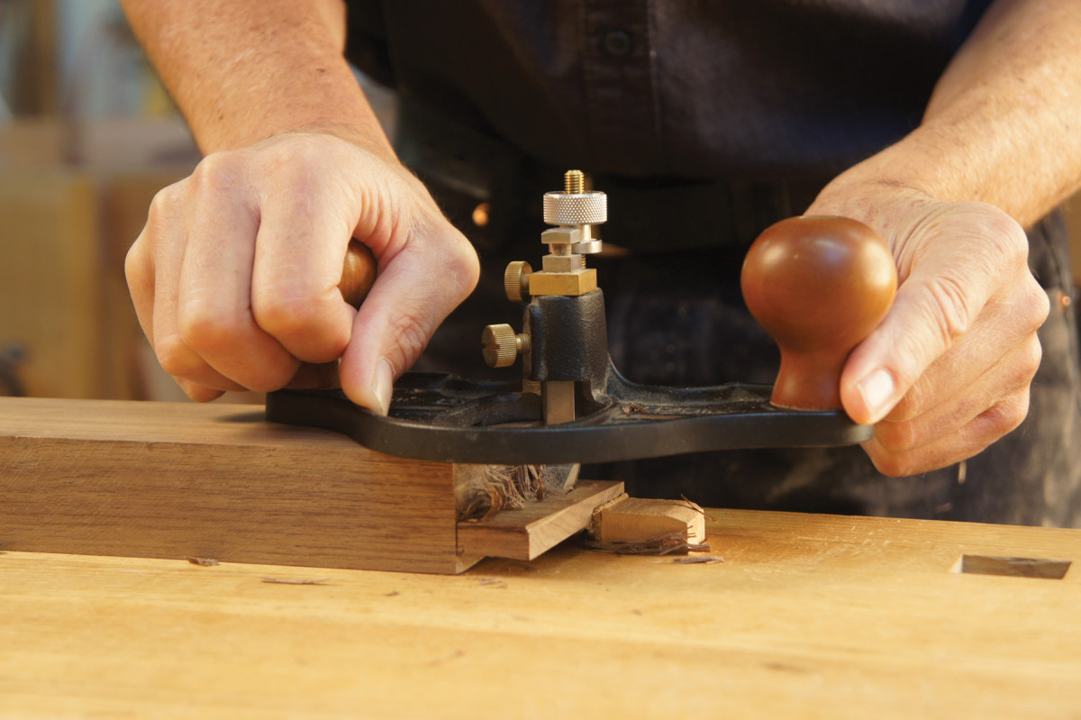
Some holds barred. Put all of the pressure on the handle over the rail stock. Two fingers are enough for the outboard handle – this will help you avoid tipping the router plane.
Angled shoulders on the lower back rail provide the leg splay. The twist on the faces of the side rails will be this same angle. Set your bevel gauge to 5°.
The simplest ways to cut consistent angles on a chair is to create a wedge. Start with 11⁄4” x 21⁄2” x 12″ stock. Square up one end of the stock, then place the bevel gauge against the end grain and mark the angle. Cut and smooth the wedge. Lay out and cut the angled ends of your lower back rail, then use the wedge to shoot these ends accurately.
Lay out the tenons on the ends of the rail, then saw the cheeks and shoulders. Fit the tenons to the lower back mortises. There are a lot of tools that will work well to clean up the tenon cheeks, but the best of these for chair work is the router plane.
Clamp the rail between the legs. It helps to make up a couple of scrap wedges at 5° out of a soft wood and faced with #220-grit sandpaper so the clamps don’t slide or damage the legs. Measure the overall width of the back assembly at the top of the rail.
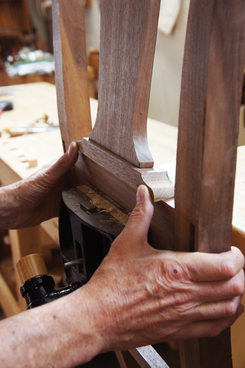
Prepare the Side Rails
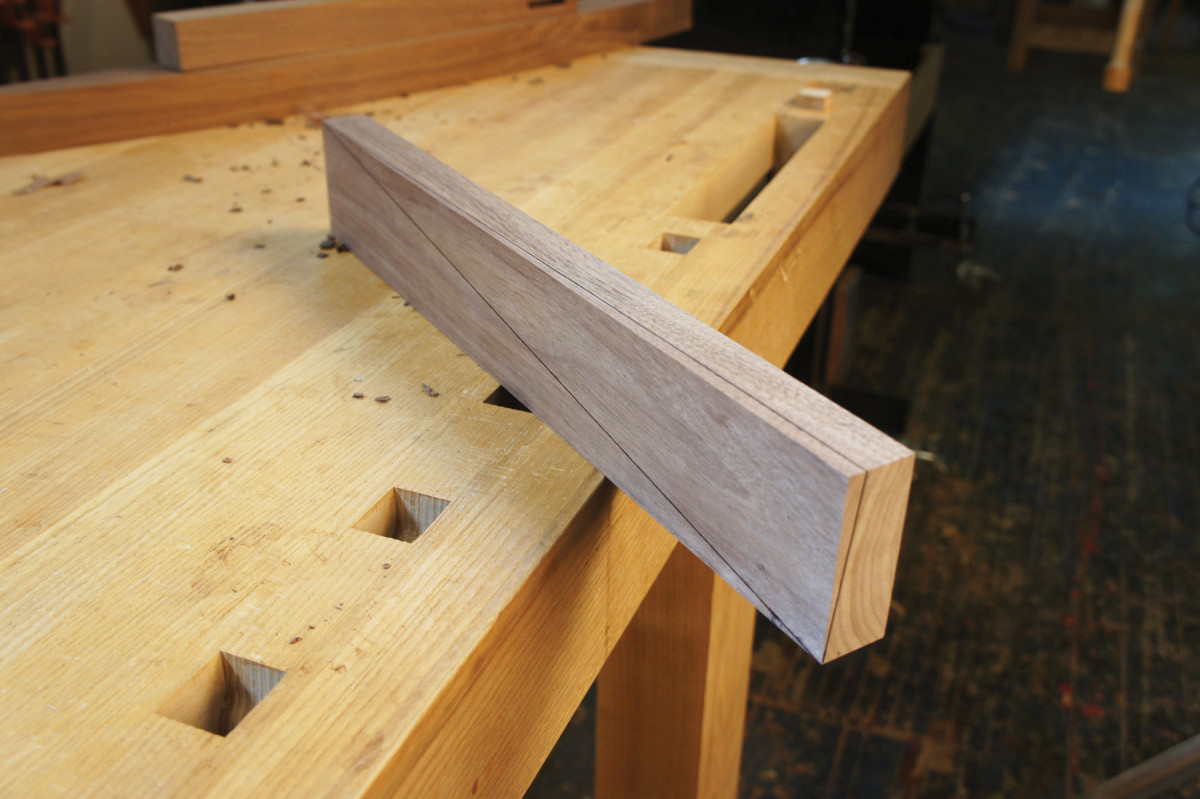
Slightly twisted. This shows the completed layout of the twist in the side rail. Note that we’re looking at the bottom of the “passenger-side” rail from the rear of the rail. If your rail doesn’t look like this….
The splay angle of the back legs requires you to create a “twist” in the side rails. This is one of the most interesting features of the chair, but it’s one few people notice unless you proudly (or annoyingly, according to my kids) point it out.
Almost twisted. This is what the side rail should look like a few passes before you’re done.
Determine the orientation of your rails. Mark the top edge and the outside face. Place the bevel gauge (set at 5°) against the back end of one of the side rails and draw an angled line from the top outside corner to the opposite edge. Mirror this on the other side rail. Transfer the lines around from the ends onto the bottom edges, then draw a line from this point to the front bottom corners of the rails. Complete the layout of the twist by drawing a line on the outside faces of the rails from the back top corner to the front bottom corner.
All of this layout defines the wedge of wood that you will plane off to create the twist in each side rail. Hold your plane at approximately the 5° angle and take tapering cuts. Proceed carefully until you hit the lines.
Side Rail Lengths & Angles

 I drew up a simplified plan view of the chair on a scrap of plywood ripped to 143⁄4” (the perpendicular distance between the inside of the front and the back legs) and at least 10″ long, with the edges squared up. This will determine the length and angle for the side rails.
On one of the short edges of the plywood, mark off half the width of the back leg assembly at the top of the rail (this should be close to 151⁄2“). On the opposite edge, mark off 10″ – half of the 20” intended front width of the chair. Connect the marks and you’ll have both the angle and the length of the rail between shoulders. Set a bevel gauge to this angle.
Start your layout at the back of the side rails with the twisted tenons. The cheeks are marked out parallel to this face. To lay out the shoulders, measure the depth of the side rail mortises in the back legs, subtract 1⁄32“, then lay out the shoulder lines straight across the angled face and beveled across the top and bottom edges with the bevel gauge. Mark the inside face to meet the beveled lines.
Mark out the front shoulder location based on the length you just determined with your drawing. Scribe the outside face of the rail square, then the edges at the same bevel angle as at the back of the rail. Mark the inside face, then scribe the cheeks.
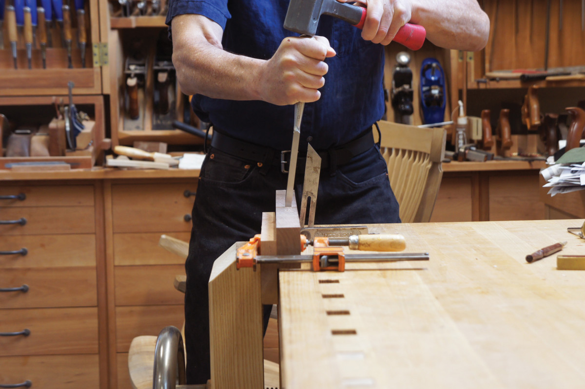
Cut the Tenons
Cut the tenon cheeks. The easiest way to cut the shoulders is with the Tenoning Frame and Chairmaker’s Saw (which I built in “Perfect Shoulders,” an article that is linked to in the Online Extras), but you can cut and pare the shoulders freehand or with an angled block as well.
The Front Rail
If all has gone perfectly, the front of the chair will measure 20″ from the outsides of the front legs. If not, adjust the length of the front rail so it fits between the legs. That’s why you left this rail until last.
The front rail’s tenons are straightforward: straight tenons and right-angle shoulders. Whew! Celebrate by carefully dry-assembling the frame.
Stretchers
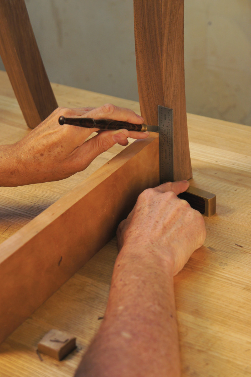
Flat to the floor. The layout in the back legs for the two side stretchers should be perpendicular to the floor, not parallel to the legs.
While the chair is together, work on the side stretcher mortises. Clamp the chair’s joints tight. Make a block of 3⁄4” x 3 5⁄16” x 18″ and use this block to mark the bottom of the stretchers, then measure up 1⁄8” and 1 1⁄8” for the location of the bottom and top of the mortises on both the front and back legs.
The stretcher mortises in the back leg are different than the side rail mortises; they are perpendicular to the floor, not parallel to the edge of the leg. This is to account for the bare-faced tenons, and are different from the side rails. Use a square on the bench to lay out the mortise sides. The top of these mortises should be 1⁄2” to 7⁄8” away from the outside faces of the legs.
The faces of the stretchers should wind up inset 1⁄16” from the edges of the legs.
Complete the layout by scribing the sides of the front stretcher mortises 1⁄8” and 7⁄8” away from the outside edges of the legs. Don’t chop anything just yet.
The Stretcher Angle
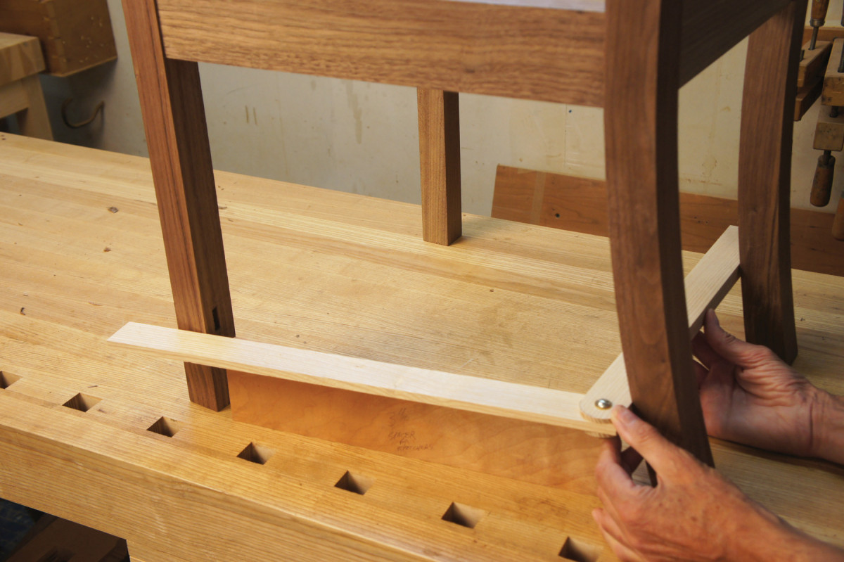
Quick-&-dirty layout tool. The angle for the slat stretcher is different than that for the side rail. An improvised shop-made bevel gauge is an easy way to figure out this angle.
The stretcher mortises must be chopped at the stretcher angle, which is different from the side rail angle, because the rear legs sweep back. The height of the stretcher on the leg is important in figuring out this angle.
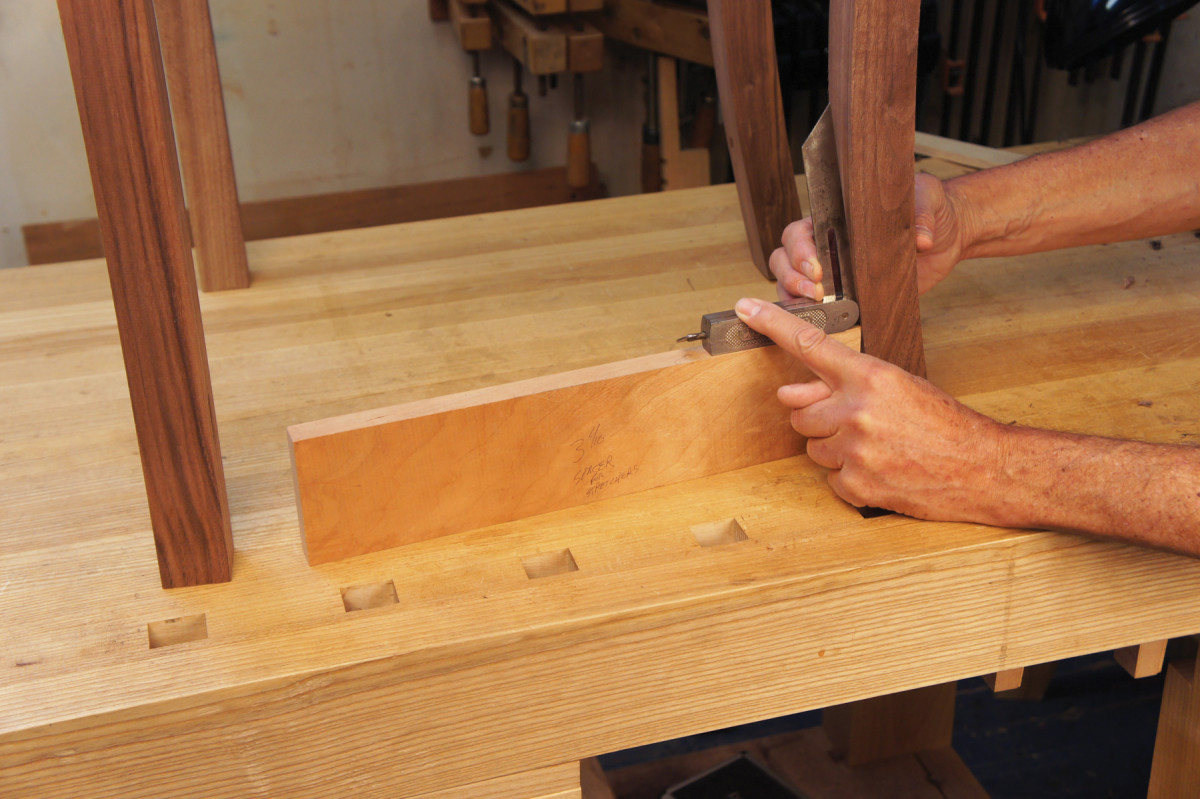
I made up a shop-made bevel gauge for this and placed it on top of the 3 5⁄16“-wide layout block, and aligned it with the front outside corner of the back leg and the rear outside corner of the front leg.
You’ll also need to set a second bevel gauge for the angle between the straightedge and the sweep of the back legs.
Measure the length between the legs at the bottom of where the stretcher will go. This will be the longest shoulder to shoulder distance between tenons. Because these are much smaller mortises, I didn’t bother with the paring block.
Double angles. To make things interesting, the back of the side stretcher has a compound angle. This gives you the secondary angle you need.
Instead, use a cut-off from band sawing the legs to support the leg and position it. Fit the side rail into its mortise and be sure that the top and bottom edges of the rail are perpendicular to your bench. Align your chopping with the rail so the mortise goes into the leg parallel to the rail (as seen from the side). The angle in plan view is different, and is guided by your oversized bevel gauge.
The mortises in the front legs are easier because you only need to worry about the angle from the bevel gauge.
The Side Stretcher Twist
Hidden strength. A bonus half-blind dovetail joint is underneath the stretchers.
Before you can cut the tenons on the side stretchers, plane the same 5° twist into them that you created on the side rails. The process is the same as it was for the rails.
Note that the stretcher tenons are half-tenons (or bare-face tenons). Mark the tenon cheeks from the inside face of the stretchers.
Start with the front tenon (the easier one), and mark out the splay angle on the top and bottom of the stretchers, the straight outside shoulders and the tenon thickness. Saw and pare away the waste.
Measure the shoulder-to-shoulder distance on the bottom outside corner of the stretcher. Use the two bevel gauges to scribe the compound-angled shoulder of the rear tenon. Scribe the tenon thickness, then cut away the waste. Pare to your shoulder lines, adjust the fit of the tenon and see if the stretchers fit.
The Rear Stretcher
The rear stretcher is easier. Clamp together the back of the chair and hold your slat stock up to the legs so the mortises are centered. Clamp the slat stock in place, then scribe the shoulder lines. Verify that these are the same 5° angle as the lower back rail. Lay out and cut the rabbet that will make the tenon on the front face of the stretcher. Test the fit.
The Cross-stretcher
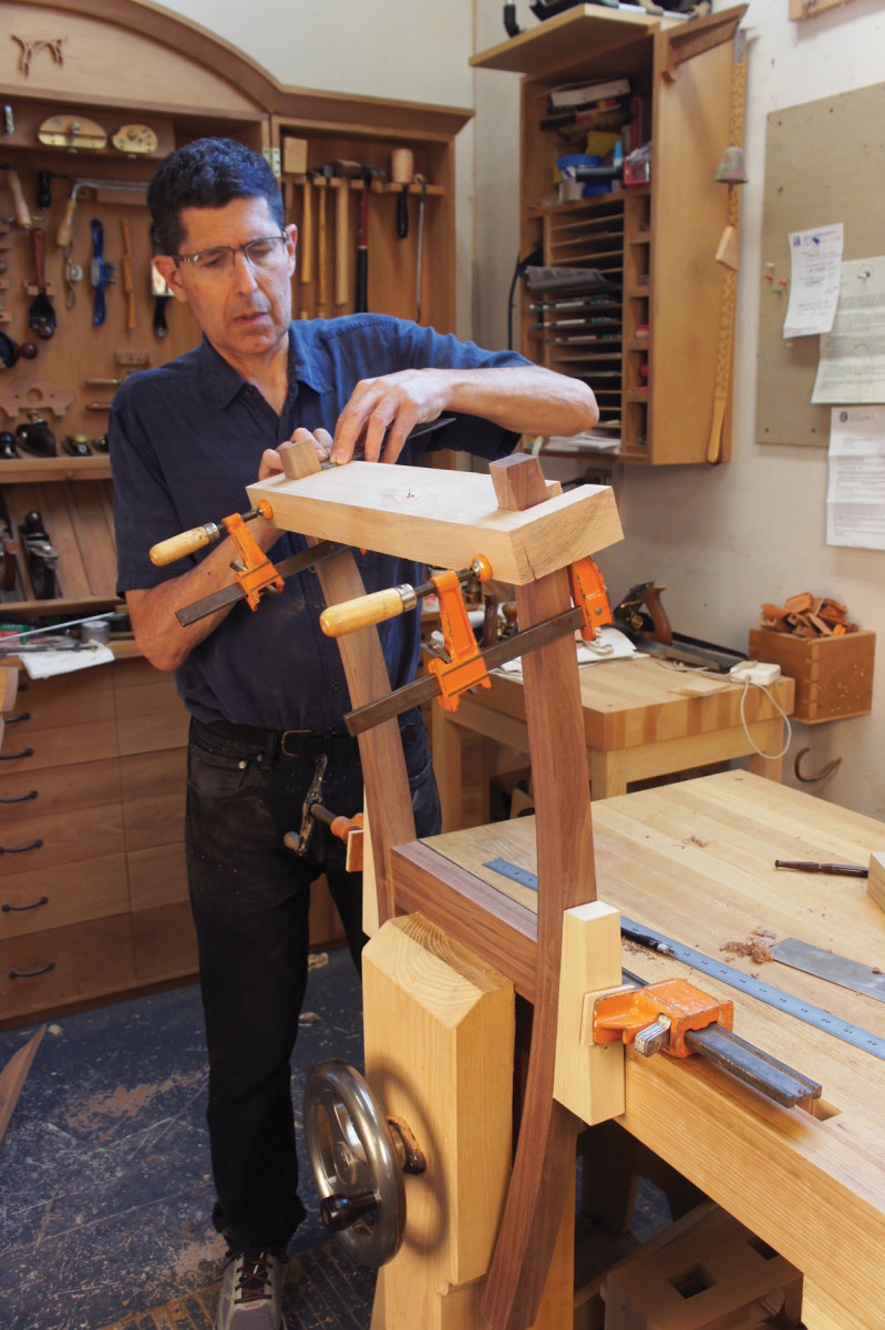
Joinery insurance. Make sure that the shoulders at the tops of the legs are aligned perfectly with a setup like this.
All that remains on the undercarriage of the chair is the cross-stretcher. Dry fit the rails, stretchers and legs, and clamp everything up. Flip the chair assembly upside down.
Measure 6″ back from the front legs and lay out dovetail sockets for attaching the cross-stretchers. This dovetail will also be also bare-faced, in that the front face of the cross-stretcher makes up one side of the tail. Cut the dovetail sockets and chisel out the waste.
Set a bevel gauge to the angle between the center and side stretcher and cut the bevel on one end of the center stretcher. Scribe the other end to the correct length and bevel it as well. Lay your cross-stretcher stock on the side stretchers so that the front face is in position over the dovetail socket. Scribe the beveled shoulders, then lay out the depth of the notch that will allow the cross-stretcher to fit flush with the side stretchers. Lay the center stretcher in place and scribe the angled faces from inside the sockets.
Chisel away the wood that makes up the angled face of the dovetail. Then cut the rabbet that allows the stretcher to sit flush with its companions. Fit the stretcher.
The Crest Rail
Guided by the bevel. Watch the negative space between the bevel gauge and the mortise chisel to get the angle right.
Clamp the back legs and lower back rail. Lay this assembly on the blank for the crest rail and mark where the legs will meet it. Lay out the mortises based on these marks, about 1⁄8” in from the outside edges of the legs and centered on the thickness of the rail. Chop the mortises to depth, then clean up the side walls.
Measure up 17 1⁄8” from the top of the back rail and make marks on the inside back corner of the legs for the crest rail shoulders. Lay out the cheeks at right angles to the shoulders, and saw these a little outside the layout lines. Fit the leg tenons to the crest rail mortises. Dry-fit the crest rail in place with the rest of the back assembly.
The back splat will need to be angled back so it aims for the lower back rail and shoe. Use a straightedge to set a bevel gauge at the angle for the splat. This will be the angle of the long mortise in the crest rail for the back splat, and for the shoulder of the open-faced tenon of the top of the splat.
Chop and pare the long mortise for the back splat. Lay out the crest rail shape. Cut the rail to shape, then smooth with spokeshaves, rasps, scraper and a chisel for the meeting points of the curves. Leave a little bit of extra wood where the crest rail meets the legs to trim after glue-up.
The Shoe
The shoe is a shaped component separate from the lower back rail, into which you cut a long mortise for the bottom of the splat. The bottom of the shoe is planed to fine tune the fit of the back splat to the chair. Lay out the long mortise for the splat, then chop and pare. The mortise is at right angles to the top surface. Fitting the shoe – and angling it – comes after the work on the splat.
The Back Splat
Determine the rough length of the splat and smooth its faces before cutting the joinery. Cut bare-face tenons on the back of the board at the top, and the front at the bottom. Cut back the angled shoulders on the upper tenon away from the line, then carefully pare to the scribed lines.
Cut the bottom as you did the top, but without the angle. Saw out the shape of the splat, and smooth its edges.
Fit & Shape the Shoe
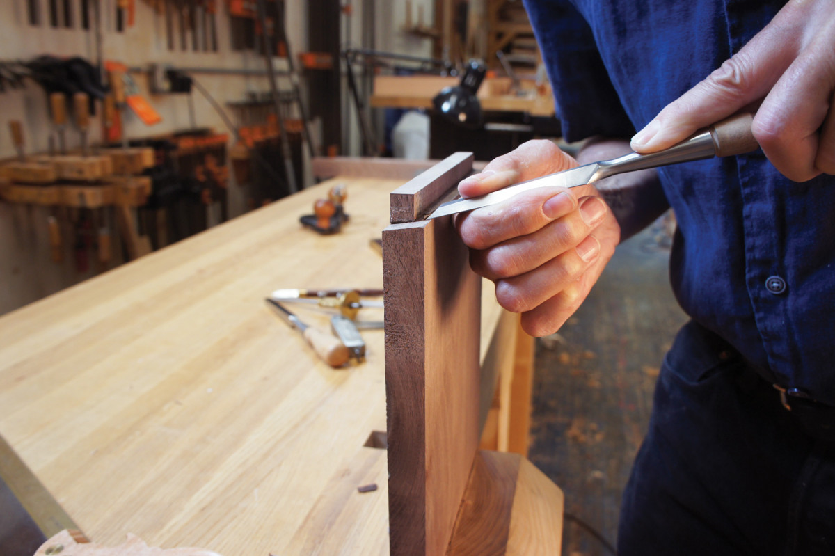
A quick fit. Paring the angle along the face of the splat is easier than it looks. There’s not much wood to remove, and you can undercut the shoulder. A sharp, wide chisel will help you keep the lines straight and clean.
Assemble the back of the chair with the lower back rail, crest rail, shoe and splat. There will be a gap between the shoulders of the rear legs and the crest rail flats. Mark and plane the angle on the underside of the shoe to get a perfect fit. Finish shaping the shoe.
Beyond Joinery
The joinery is done. Before assembly, rabbet the tops of the rails and the front legs for the drop-in seat. Assemble in stages to keep things under control. The sides of the chair come first.
Spread glue in the mortises and lightly on the tenons, then assemble a side and clamp tight. Once both sides are done, add the front rail and the lower back rail and back stretcher to complete the next stage of the glue-up. Then add the crest rail. The splat and shoe are next. The final step is to add the dovetailed center stretcher underneath.
Final Steps
A fine fit. You should be able to push the shoe into place snugly without opening the crest rail-to-leg joints when it all fits.
The hard stuff is done, but there are more details to take care of. Add corner blocks to reinforce the joinery and provide an (optional) attachment point for the seat. You also need to level the legs on the chair so it sits reliably flat. Cut the slip seat from 3⁄8” or 1⁄2” plywood (and send it out for upholstery – or do it yourself).
Apply your choice of finish to the chair. And finally, add glides to the bottom of the legs to protect the legs and the floor.
Here are some supplies and tools we find essential in our everyday work around the shop. We may receive a commission from sales referred by our links; however, we have carefully selected these products for their usefulness and quality.


